
6 Building the Inside
Contents
Building an Adjustable Enlarger Baseboard
The Lighting Circuits
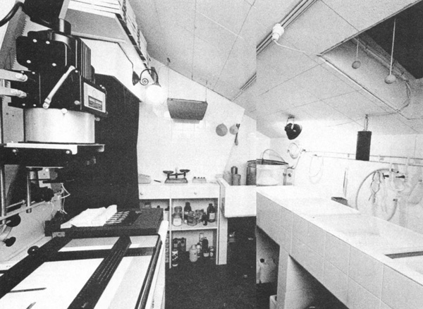
Lighting the Darkroom
Lighting a darkroom has similar considerations to taking pictures: eliminating unwanted light and controlling the light you do want. Later we will discuss making the room dark by eliminating unwanted light. This section deals with controlling the light you do want.
General Lighting. There should be sufficient illumination when the main lights are on to clean the room and to do general work that is not involved with light-sensitive materials. For this purpose, regular incandescent or fluorescent fixtures are normally used. The switch for the lights on this circuit should be separated from the other darkroom lights or should have a switch guard to prevent it from being turned on by mistake. The number of lights depends to a large degree on the size of the darkroom or workroom. Generally, two 100-watt fixtures are sufficient.
Safelighting. Safelighting provides filtered light that will not affect light-sensitive materials. Each type of material has a specified filter. Using the wrong filter can reduce the safety factor or offers no protection at all. The intensity of the safelight desired varies from photographer to photographer. Some like a darkroom that is as bright as possible, and others a more moody room with cones of safelight only at key spots near the enlarger and print-developing trays. Use your own judgment in selecting the type of lighting for the room you plan.
Print-Viewing Lights. When the print comes out of the fixer, it’s usually evaluated to determine what should be modified to make the next print better. To make an accurate evaluation you need proper lighting. Too little light or too much of the wrong kind can seriously affect your decision. Light that is too bright will make prints look weak and washed out, whereas light that is too weak will make them appear to be too dark. The solution is to have a viewing light in the darkroom that best represents the light in which the print will eventually be viewed.
With black and white prints, all you need worry about is light intensity. If you are printing for gallery display, remember that the gallery lights are much brighter than in the average living room or bedroom. Most galleries will have lighting of 80 to 100 foot candles, and that intensity should be matched by the print-viewing light. A dimmer switch, available in hardware stores, can be used on the print-viewing light and calibrated to various viewing environments.
With color prints, the light in the darkroom ideally should also be the same color balance as the light by which the prints will be finally viewed—often, though not always, daylight. For convenience, many photographers simply match their darkroom light to a daylight balance. Kodak recommends for viewing color prints a light of 50 foot candles or more, a color temperature of approximately 4,000° K, and a color-rendering index of 85-100. Deluxe cool-white fluorescent lights come close to these requirements. They should not be used for viewing in conjunction with ordinary incandescent lights, which are of a different color balance.
Light Table. It is generally helpful to have a light table built into or sitting on the dry-side counter. A light table is the ideal way to view negatives while making selections for enlargements. The light table can be covered with a large safelight filter so that it can be left on while printing (this will work only if you are printing in black and white), or it can be controlled with a dimmer switch.
Luminous Tape or Paint. You should consider the use of phosphorescent tape or paint to identify key items in the room that you might need to find in the dark, such as focusing magnifier, print tongs, and drawer handles. It’s also helpful to indicate any sharp corners so they can be avoided in the dark. Even with good safelighting, the room will be dark when working with film and color materials.
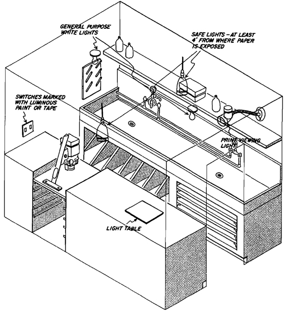
General Lights. These are standard ceiling fixtures giving sufficient light to work and clean the room when light-sensitive materials are not being used.
Safelights. The number of safelights is determined by the size of the room and the intensity of the light desired. Safe-lights should be no closer than 4’ from enlarger baseboard or processing trays, otherwise fogging of paper is possible.
Print-Viewing Light. Most photographers like to check their prints after they have been in the fixer for a few minutes. It’s convenient to have a light nearby, because prints cannot be evaluated accurately under safelighting regardless of how bright it is.
Light Table. A small light table built into the counter is handy to use in selecting negatives.
Calibrated Print-Viewing Light
If you want to make prints that are adjusted for the brightness of light available where your photographs will be viewed, you can calibrate your darkroom print-viewing light using a regular light meter, a standard photographic gray card, and a dimmer switch installed on the print-viewing light. First determine where the prints will be viewed, either in the home or in a gallery. Place the gray card in the position the print will occupy and illuminate it with the lights that will be used to illuminate the print. Take a reading from the gray card with the light meter.
Now place the gray card under the darkroom print-viewing light in the position where prints will normally be set for evaluation. Install the dimmer switch according to the instructions. While watching the light meter, gradually increase the light intensity until the reading matches that obtained at the position the print will eventually occupy. Mark the dimmer switch to indicate its position so you can repeat the setting without additional measurements. If you print for a number of viewing conditions, you will eventually have a dimmer switch with various settings indicated. Experiment with a trial print on the particular printing paper you are using, because some papers dry down to a tone that is darker than when they are wet.
Lighting Equipment
Choosing a Safelight
Safelights contain a bulb and a colored filter. As the light from the bulb passes through the filter, portions of it are blocked and only light of a certain color is allowed to pass: this light will not expose your enlarging paper (it will affect film, however). Although the light from a safelight is dim, it does allow you to see in the darkroom while making proofsheets and enlargements. Two considerations when buying a safelight are where to put it and what kind of filter to use.
Kodak Safelight Filters
Kodak Safelight Filters are scientifically designed for safelight lamps to provide maximum safe illumination plus protection from white light when using sensitized materials:
-
OA (greenish yellow)—for black-and-white contact and duplicating materials, and projection films
-
OC (light amber)—for contact and enlarging papers
-
OO (light yellow)—for flash exposure technique with Kodak Contact Screens (available only in 5 1/2” diameter)
-
No. 1 (red)—for blue-sensitive materials, most photo-typesetting materials, Kodagraph Projection, and some Linagraph Papers
-
No. 1A (light red)—for slow orthochromatic materials, Kodalith and Kodagraph orthochromatic materials, and high-resolution plates
-
No. 2 (dark red)—for fast orthochromatic materials, some green-sensitive x-ray films, Ektaline Papers, and Orthochromatic Linagraph Papers
-
No 3 (dark green)—for some panchromatic materials
-
No. 6B (brown)—for blue-sensitive x-ray films
-
No. 8 (dark yellow)—for some Eastman Color Print and Intermediate Films
-
No. 10 (dark amber)—for Vericolor slide film 5072, Vericolor print film 4111. and Panalure papers
-
No. 11 (appears opaque, transmits infrared radiation)—for use with infrared scope and similar inspection devices (available only in 5 1/2” diameter)
-
No. 13 (amber)—for all Ektacolor, Panalure, Panalure and Resisto Rapid Pan Papers
-
GBX-2—for all blue- and most green-sensitive medical and dental x-ray films
Safelight Location
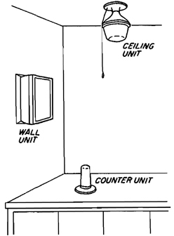
Where to Put It. Safelights can be screwed into existing ceiling or lamp fixtures, mounted on the wall, or placed directly on your counter. To reduce the chance of fogging (an overall graying of your paper), keep in mind that the safelight (with a 15w bulb) should be located at least 4’ (1 1/4 m) from where your paper is exposed and processed.
What Kind of Filter
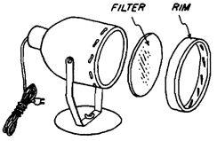
What Kind of Filter. The instruction sheet packed with your paper (open the package only in the dark to remove it) specifies a particular type of filter. Most enlarging papers require a light amber filter, such as a Kodak Wratten OC. Safelight filters are usually purchased separately from the safelight itself and come in a variety of shapes and sizes.
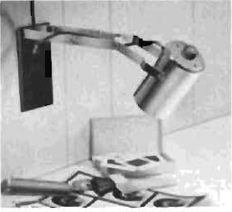
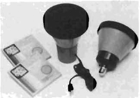
Print-Viewing Light. A small wall-mounted light to use in evaluating prints is very useful. This model from Edmund Scientific has important features, such as a shielded light for increased brightness, and a swivel bracket that allows it to be positioned as needed. The arm also slides into a closed position only 3” long and extends out to 11 “.
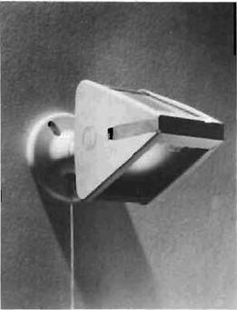
Kodak Two-Way Safelight. This Kodak two-way safelight is a popular model. It is inexpensive and effective. The light is directed in two directions for even illumination. To install, screw it into an existing socket and you’re ready to print.
Courtesy Eastman Kodak Company
Thomas Sodium-Vapor Safelight. This sodium-vapor safelight puts out light from a very narrow part of the spectrum, one which has the least effect on photographic papers, but to which the human eye is most sensitive. The result is a light bright enough to read the fine print in the next contract for your photographic services. This is an excellent choice if you want a bright darkroom in which to work.
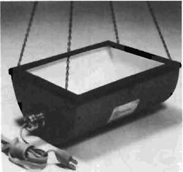
Utility Safelight. The Kodak utility safelight model D is a good example of a safelight that can be suspended from the ceiling. The light is then reflected downward from the ceiling for even illumination throughout the room.
Courtesy Eastman Kodak Company
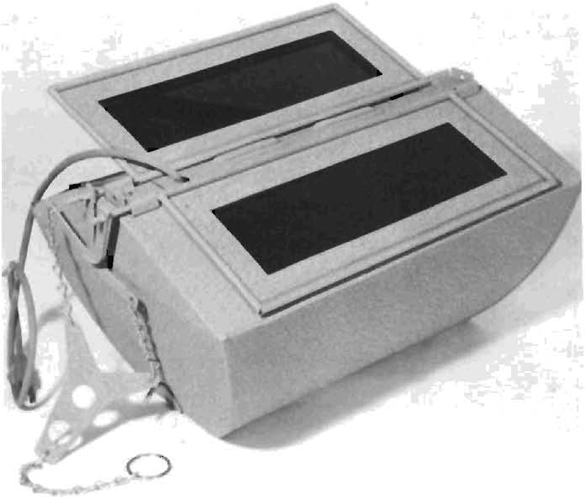
5 1/2” Round Safelights. This 5 1/2” safelight system consists of a housing, filters, and a universal base. It uses standard 5 1/2” filters available from Kodak and others. The universal base can be mounted on a wall or ceiling or stood on a counter top. An alternative socket base allows the safelight to be screwed into an existing light socket.
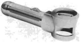
Illuminated Magnifier. A combination magnifying glass and flashlight that is useful for examining 35mm contact proof sheets.
Building a Darkroom Sink
A sink is a basic piece of darkroom equipment. A long sink made out of wood, plastic, fiberglass, or stainless steel will hold print-processing trays plus the print washer.
Darkroom sinks make it easier to keep the darkroom clean by containing spills that, at the end of a session, can be flushed out with a hose. Because many chemicals dry to a powdered state that can be carried by air currents onto sensitive materials, it is essential that they be removed, and the sink provides the most efficient way of doing so. In addition to improving cleanliness, a darkroom sink allows all of the processing trays to be immersed in a water bath to help maintain their correct temperature.
You can buy a sink, but the vast majority of photographers build their own sinks out of plywood, which is then caulked and sealed with epoxy or other waterproofing material.
Rail to Lean On
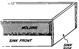
Rail to Lean On. Neither 1/2” nor 3/4” plywood provides much of an edge to lean on. Since you will want to lean on the sink while rocking trays, it helps to install a piece of l/2”-wide casing (or molding) along the front sink frame to widen the top edge. This will make the sink front much more comfortable to work on.
Making the Sink Sidewall Frame
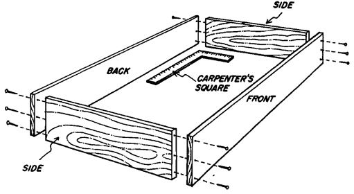
Making the Sink Sidewall Frame. The sink frame can be made out of a variety of materials but the most popular is 1/2” or 3/4” plywood. Because the sink will be painted, a lower grade of plywood called “plug and touch,” which is finished on one side, is suitable for its construction. The sides should be approximately 8” deep and long enough and wide enough to hold the number of processing trays you plan on using (see the section on “Wet-Side Cutouts” in Chapter 4 for various sink sizes). After the pieces are cut to the correct length they should be glued and then nailed or screwed into place. Use a carpenter’s square to ensure that the corners are square when assembling.
Sink Frame
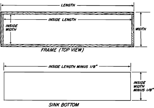
Building and Installing the Sink Bottom. After you have finished the frame, measure the inside dimensions. Cut a piece of 1/2” plywood so that it fits into the sink side-wall frame with as little clearance on all sides as possible. As a starting point, the plywood should be cut 1/18” shorter and narrower than the inside dimensions of the sink frame. If it does not fit, sand off the excess wood until it fits snugly into the frame.
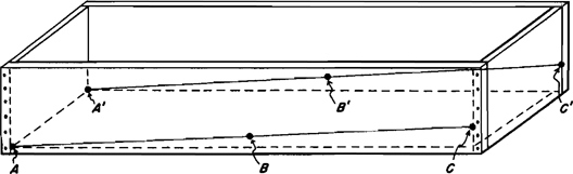
Measuring for Bottom Slope. After the sink bottom has been cut to size, it must be installed in the sink so that it tilts enough to drain toward one end or the other. Do this by installing the bottom supports at gradually increasing heights along the length of the sink. Cut these supports out of 1 × 1” or 1 × 2” lumber to a length equal to that of the sink end pieces.
To build in the slope at the bottom, draw a sloping line down both long sides of the inside of the sink frame as a guide line for nailing in the cross pieces. Make one mark at point A and A’ flush with the bottom of the sink frame. Halfway down the sink, make a mark at B and B’ 1/8” above the sink frame bottom, and at the other end of the sink (C and C’), place a mark indicating a point 1/4” above the sink bottom. Connect these three points with a straightedge and you will have a sloping line as a guide for where to nail the bottom edge of each support piece.
If your drain will be in a far corner and you decide that you also need a front-to-back slope, you can raise the A, B, and C, or A’, B’, and C’ measurements an additional 1/8” above the measurements on the other part of the frame.
Installing Bottom Supports
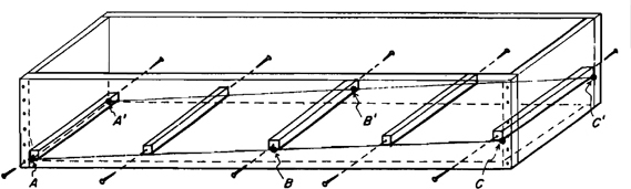
Installing Bottom Supports. Hold each support cross piece in position and drive a long nail through the front of the sink and into the support. Since you will be nailing blind, it may help to first measure where the support is to be located inside the sink and then transfer this measurement to the outside. Nail the support on the other side (back) of the sink, and continue with each of the subsequent cross pieces. Make sure that the bottom of each cross piece is aligned with the guide line that indicates the tilt of the sink bottom.
When all of the supports are nailed in place, insert the sink bottom and nail it into place.
Waterproofing the Sink
The assembled sink must be made waterproof before it is used. The first step is to caulk all of the seams on the inside of the sink using an acrylic caulking compound, which comes in tubes and is available at most hardware stores or lumber supply houses. Run a bead around the bottom of the sink and up the four corners. To make it form a smooth surface use a large 3/4” to 1” wooden dowel to make a curve in the caulk. This is done by running a bead of caulk the length of the seam and then running the dowel along the bead, smoothing it as it is pulled along.
The sink can now be painted with a waterproofing material. Epoxy paint can be used, or you can fiberglass the inside. The demands put on the typical sink do not require the use of fiberglass cloth but it is commonly used. (Strips of fiberglass cloth can be used in conjunction with epoxy resin to seal the seams if you choose not to use acrylic caulk.) by itself will tend to crack if the sink is moved or pushed out of alignment. We can recommend the following sink coatings:
Sherwin-Williams Tile Clad II comes in two parts and, when mixed and applied, dries to a hard surface finish.
Epoxy Resin is the most commonly used coating. It can be applied like paint directly on the wooden sink and will provide sufficient waterproofing. Seams can be sealed by embedding cloth tape in the wet and then repainting the top surface with more
One of the best places to find good sink-waterproofing materials is a marine supply store. Anything used to keep water out of a boat can also be used to keep water in your sink. New waterproofing products come on the market frequently, so you should visit a good store if you want to know what the latest products are.
Building a Sink Stand
After the sink itself has been completed, it is necessary to find a place to put it other than flat on the floor. If the darkroom is in a bathroom or other room that is used for more than one purpose, the sink can be mounted on chair rails (1 1/2” × 11 /2” molding) along three walls of the room. This allows the sink to be removed easily and the chair rails do not detract from the room.
However, you may want to build a permanent sink stand that is sturdy enough to hold the sink and can also provide additional storage space. This section covers both of these possibilities.
Leveling the Sink
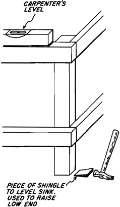
Leveling the Sink. Once the sink stand has been finished, it should be installed in the darkroom and leveled. Use a carpenter’s level and small pieces of wood such as shingle. Put the level on the top rail and level the sink lengthwise using the wood pieces to raise the low end. After you level the sink in the long direction, follow the same procedure to level it front to back.
Now place the sink itself on top of the sink stand. The sink bottom’s built-in tilt should now be at the correct angle for proper drainage.
Building the Sink Stand
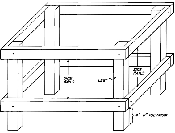
Building the Sink Stand. The sink stand should be constructed with 2 × 4s nailed or bolted together. The outside dimensions should be the same as the outside dimensions of the sink itself.
Begin by cutting the base rails to the same lengths as the sink side walls. Make two sets to provide support at both the top and bottom of the sink stand.
Now cut the four legs to the height you want the sink bottom above the floor. Because the sink bottom is actually a few inches above the bottom of the sink side-wall frame, cut the legs a few inches shorter than the ideal height to allow for the difference.
Assemble the two sets of side-rail frames for the stand, and then belt or nail the legs in place as shown in the illustration.
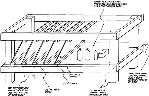
Building Undersink Storage. The space under the sink can be utilized for storage of trays and chemicals, or even for a permanently installed print-drying rack.
The simplest method is to cut a piece of plywood to fit on the lower side rails providing one large expanse of shelf. This would be fine for chemical storage.
One-half of this shelf can be converted to a tray storage area by mounting small wood strips across its width with additional strips, offset a few inches, nailed across the bottom of the top side rails. Pieces of masonite can be cut so that when installed they divide the space into a series of sloping compartments wide enough to hold the trays.
The bottom shelf can be tilted toward the front of the sink to ensure drainage should you ever store wet trays. Nail a thin strip of wood no thicker than 1/4” along the back rail before nailing in the plywood shelf. When the plywood is nailed on top of this piece it will slope toward the front of the sink stand.
Installing Counters
Installing Dry-Side Counters and Storage
Counters and storage cabinets can be custom-made for a darkroom, but they can be very expensive. The know-how required to build them yourself is also extensive. The ideal solution is to use kitchen cabinets and post-formed (seamless) counter tops. Cabinets can usually be picked up quite cheaply at sales or in used condition. Since visual appeal is not as important in the darkroom as it is in the kitchen, damaged units, poor sellers, and inexpensive units all become candidates for your Darkroom.
Base Units. Counter base units come in standard widths from 9” to 42” in increments of 3”. They are standardized at a 24” depth.
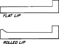
Counter Tops. Pre-made counter tops are available in long strips 25” wide; the building supply company can cut them to the length you need. There are two styles available, one with a flat lip on the front edge and one with a rolled lip. Avoid the rolled lip since large items such as a paper trimmer will not rest flat on the counter.
Currently, pre-formed counter tops cost less than $15 per running foot. A counter top for a large darkroom with a 10’ dry side (minus 30” for the enlarger base) would cost approximately $115. It would be difficult to custom-build one for less, especially if tools had to be purchased.
Dry-Side Wall Cabinets
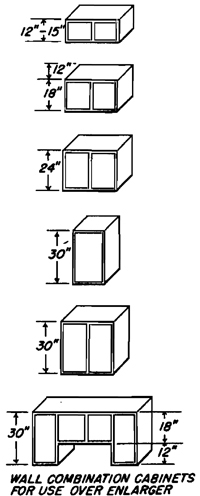
Dry-Side Wall Cabinets. Wall cabinets come in lengths of 24” to 48” in increments of 3”. They range in height from 12” to 30”.
Wall Cabinets. Wall cabinets are also available from building supply companies and can be installed above the dry-side base cabinets for additional storage. They come in the same standard widths as the base cabinets, but are only 12” deep.
Dry-Side Base Cabinets
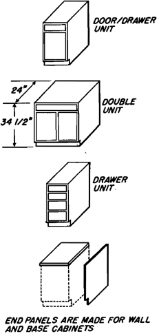
Dry-Side Base Cabinets. Base cabinets are available in sizes ranging from 9” to 48” in increments of 3”. They come with doors, drawers, or a combination of both. Although their standard height is 34 1/2” (36” once the counter top is installed), they can be raised by building a base under them.
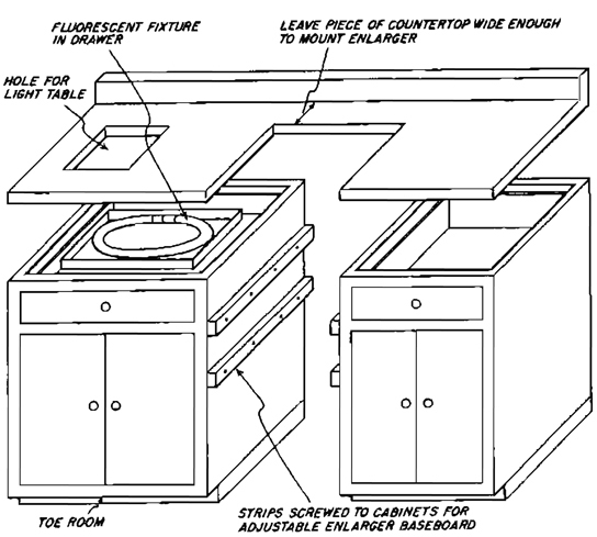
Dry-Side Assembly. This view shows how the dry-side cabinets can be assembled to accommodate the enlarger mount, adjustable easel baseboard, and light table.
When ordering pre-formed counter tops, you can have them custom-cut and finished for both the enlarger and the built-in light table.
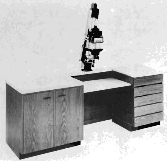
Professional Cabinets. This dry-side cabinet is a good example of a professionally designed and manufactured unit. Such units are extremely well-made, but the high quality comes with a relatively high price tag.
Building a Print-Drying Rack
A homemade print-drying rack utilizing fiberglass screens is easy to build and can either be made to stand alone or built-in. The rack consists of two major elements:
1. Frames with fiberglass screen stretched over them. The frames provide the rigidity required to keep the fiberglass flat and tight. The fiberglass screen supports the print, but at the same time allows air to circulate freely on all sides of the print, contributing to even, fast drying. Fiberglass screen should be used because it is impervious to darkroom chemicals and will not rust. It is also nonabsorbent, so if a poorly washed print does come in contact with it, the screen can be washed clean to protect subsequent prints.
The frames on which the fiberglass screens are stretched can be made out of 1” × 1” wood cut at a 45° angle to make corner joints similar to a picture frame. For this you need a mitre box and saw. Frames can also be constructed out of aluminum window screen frames. Aluminum framing members can be bought either in long lengths or precut to the size you desire. Wooden canvas stretchers available in artists’ supply stores also work quite well and are already pre-cut, making tools unnecessary.
If you choose to make the racks out of aluminum framing, you will also need what is called “Spline,” the rubber gasket that locks the screen into the frame, and an installation tool.
2. Rails on which the frames will slide in and out and a cabinet to hold them. The rail can be either aluminum angle iron, wooden rails made out of 1” × 1”, or wood molding that is L-shaped. Regardless of which is chosen, they should be installed level and parallel so the frames slide in and out easily. They should be spaced approximately 3” or more apart to allow for free air circulation in the rack.
If the print-drying rack is to be installed under the sink, be sure to build the sink and its stand first so that exact measurements for the print-drying rack can be taken from the actual unit (see “Building a Sink Stand” above). This will ensure that the rack fits into the existing space.
The Easy Way Out
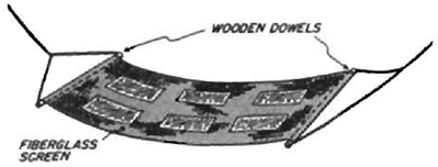
A simple print-drying rack can be made with a long piece of fiberglass screen, two wooden dowels, and some string. The dowels are stapled to each end of the screen and the unit is suspended like a hammock. When not in use, it can be rolled up and stored. It’s also easy to keep clean because it can be washed in the sink.
If you use an old (or new) window shade roller in place of one dowel and attach it permanently to a wall you can pull the screen out when needed. Just attach it to a hook on an opposite wall. When finished, you unhook it and it rolls back up by itself. Be sure the roller is mounted with enough space between it and the wall to allow the fiberglass screen to roll all the way up.
“Hammock” on Window-Shade Roller
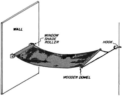
“Hammock” Drying Screen
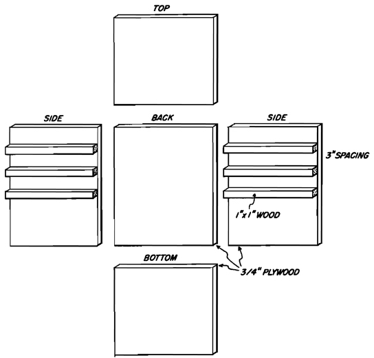
Building the Print-Drying Rack. The cabinet needed to hold the fiberglass frames can be made out of either I /2” or 3/4” plywood. The thicker material will give a more stable cabinet. Begin by determining the size frame you need to hold your prints, and then calculate the size cabinet you will require to hold frames of the chosen size.
Measure the two side pieces so they are the exact length of one of the dimensions of your frames. The back piece should then be measured off so it is as wide as the other dimension of the frame, plus an additional amount at each end (either 1/2” or 3/8” where it will overlap the side pieces).
The back and side panels should be the same height. The height depends on where you plan on putting the cabinet and the number of drying frames you want it to hold.
Measure the top and bottom panels of the cabinet. They should be the same width as the back panel and the same length as the sides, plus an additional 1/2” or 3/4” where they will overlap the back panel.
Now measure where the rails on which the frames will rest will be placed. They should be 3” apart. Begin by measuring down from the top of the side panels 3” and draw a line across each panel.
Measure off another 3” and do the same. Continue doing this for the entire length of both panels. Now cut 1” × 2” lengths of wood as long as the panel is wide. Cut as many as you have marked on the side panels. Nail and glue them into place using the lines drawn to ensure that they are level and parallel.
Nail and glue the side panels to the back panel, and then do the same with both the top and bottom panels. The cabinet is now complete with the frame guides in place.
Details of the Frame Supports
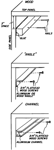
Details of the Frame Supports. These drawings show how various types of frame supports can be attached to the side panels of the print-drying rack.
Making the Drying Frames
After the cabinet has been completed, the next step is to build the frames to hold the fiberglass screen. There are three principal ways to make these screen frames: wooden frames, canvas stretchers, and aluminum frames.
Wooden Frames
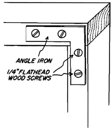
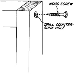
Wooden frames can be made out of any lumber from 1” × 1” up to 1” × 3”. Begin by measuring the inside of the print-drying cabinet. Make the frames about 1/8” to 1/4” smaller to allow them to slide in and out easily. The frames can be mitred or square cut at the corner joints. Because there is very little weight on the screens, the joints do not have to be extremely strong. The corners of the frames can be joined with screws, nails, angle irons, or corrugated nails. A Stanley “Sure-Drive” set can save you a great deal of time. This makes firm joints and is both easier and faster than using either nails or screws. Wooden frames should always be painted to keep them from absorbing chemicals.
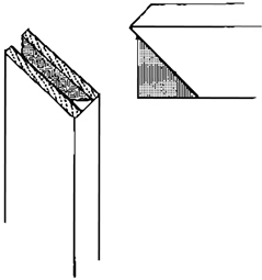
Frame Assembled with Angle Irons
Frame Assembled with Stanley “Sure-Drive”
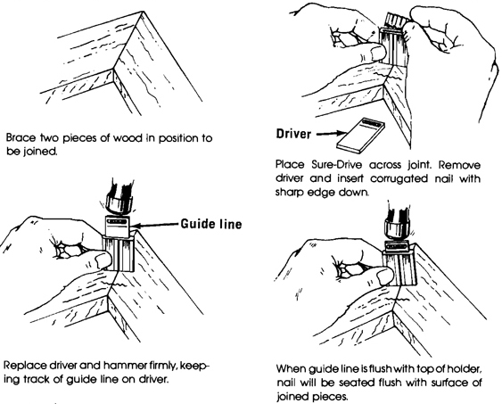
Frame Assembled with Stanley “Sure-Drive.” This fastening device and tool is ideal for making a large number of joints in a very short time. Be sure to buy corrugated nails no deeper than one-half the thickness of your frame.
Frame Assembled with Screws
Attaching the Screen to Wooden Frames
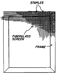
Attaching the Screen to Wooden Frames. After the wooden frame is assembled, staple the fiberglass screen to it so that the screen is tight and free of wrinkles. The easiest way is to use a staple gun to staple the screen in place. Because galvanized staples are almost impossible to buy, the heads should be touched up with varnish to prevent them from rusting. It is also advisable to paint or varnish the wooden frames before attaching the screening. This will keep them from absorbing chemicals that can contaminate subsequent prints.
Canvas Stretchers. Wooden canvas stretchers are available from most art supply stores. They come pre-cut in different sizes and can be easily assembled in a variety of combinations. The joints are pre-cut to slip together, and they can be glued or nailed to give the joint greater strength.
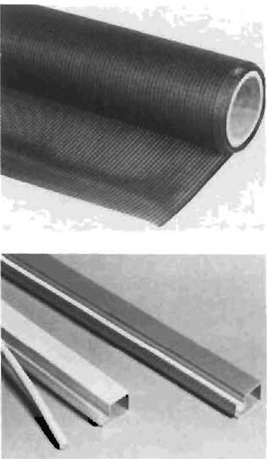
Aluminum Frame Members and Fiberglass Screen. These photographs show what the aluminum frame members look like. The round material is the “spline” and is used to hold the fiberglass screen in place once the frames have been assembled. Fiberglass screen comes in rolls of different widths. Buy the size closest to the width of your frames.
Aluminum Frames
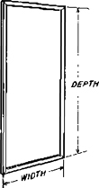
1. Measure the width and depth of the inside of your print drying rack. Mark two lengths (depth minus 1/8”) of screen section for the side frame pieces and two widths (width minus 1/8”) for the top and bottom of frame pieces.
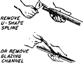
2. Remove the U-shaped splines or glazing channels from all the frame members.
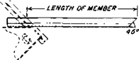
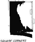
3. Mark 45-degree angles at the measured points.

4. Saw off the ends, using a fine-toothed coping or hack saw. Smooth cut ends with file or sandpaper.
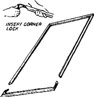
5. Insert corner locks into the two short frame pieces. Slip the two long frame pieces onto one of the end pieces. Finally, add the other end as shown to complete the frame.
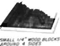
6. Cut screening to outside dimensions of frame. Cut carefully between two screen wires to keep screening square. Place frame on table and scatter scraps of frame section in the center area to hold screening level with top of frame. On large frames you may want to nail small 1/4“-thick blocks around frame to maintain squareness as shown in illustration 2.
7. Line up screening with the outside edge of the screen groove at the side and end of the frame shown. Bend the screening into the side and end grooves. When using fiberglass screen it should fit down, across, and up inside of grooves.

8. After completing operation along one side (as in step above), cut off excess screen cloth along line even with outside edge of groove in other adjacent leg.

9. Cut U-shaped splines 1/16” less than length of spline groove; make butt joints at the corners. Next, tap spline into groove using block of wood with rounded front corner (on one long frame piece) to hold screening securely. In the same manner, form screen cloth on the two short sides, cut off excess screen cloth, and insert spline. Then, complete fourth side.
Aluminum Frames. You can either buy pre-assembled aluminum frames from a window supply house, or you can assemble them yourself. To do a complete job, you will need frame members, a mitre saw, a “spline” tool, and fiberglass screen.
Building a Light Box
A light table built into the dry-side counter makes it much easier to evaluate and select negatives for printing. This is especially true if you use medium or large film formats. Holding a 4” × 5” negative up to a bare ceiling bulb gives a very unevenly illuminated image. With a light table, you can also evaluate an entire roll of 35mm film.
To build a light box, select a space separated from the enlarger by a short distance (leave working room on both sides of each) and located directly over a drawer or other unobstructed counter surface.
Purchase a metal rim frame, such as what is used to mount a sink on a ceramic working surface into a kitchen counter. It requires only a saw to cut a hole in the counter and the rest of the assembly is easy. Buy a piece of white acrylic cut to fit the frame; small pieces of acrylic are usually available at low cost from the scrap bin in supply stores.
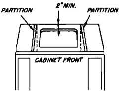
Locate the desired position of your light-table insert on the counter top, usually close to the enlarger for convenience, and check for proper clearance. Be sure that the compartment under the location is at least 2” wider and deeper than the overall size being used. This will assure sufficient room to fasten the holding lugs. Be careful not to cut the supports on the underside of the counter top.
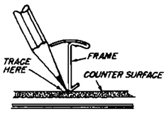
Position the frame assembly, right side up, on top of the counter in the location desired (step #1 above) and trace around the frame as shown.
Cut along the traced line carefully. This can be easily accomplished by drilling a 3/8” starter hole just inside the traced line and cutting along the line with a medium or fine-tooth electric saber saw. Be sure to keep edge of saw vertical. A manual key-hole saw may also be used to make the cutout. Use only a fine-tooth saw for manual cutting, and cut only on the down stroke to avoid splitting and delaminating the counter top surface.
(NOTE: When using an electric saber saw, it is advisable to cover the counter top surface on the outside of the traced line with masking tape to protect the surface from being scratched by the vibrating base, or foot of the saw.)
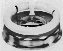
Round Fluorescent Fixture. This round fluorescent fixture by Sterling Lighting is ideal for illumination of a light table installed in the counter top.
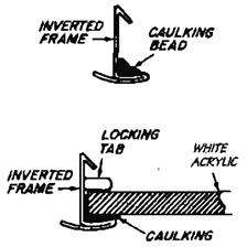
Assemble your light table insert by placing the frame upside down on a flat surface and applying an adequate bead of caulking (such as clear silicone bathtub seal) around the under-inside top edge of the frame-top flange.
After caulking the inside of the frame, insert the piece of white acrylic. With the insert positioned in the frame, bend one of the perforated press-out locking tabs in the frame, on each side of the assembly, inward to hold the insert in the frame for installation. This need not be a tight fit, as the installation lugs will secure the assembly firmly when installed.
Seal the frame on the outside by applying a uniform bead of caulking to the under-outside edge of the frame-top flange.
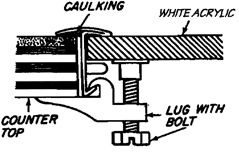
Install the light table assembly into the counter top cutout. From the underside of the counter top, attach the lugs onto the hook of the frame leg. Always place two lugs as close as possible to each side of the corner bends. Space and tighten lug bolts evenly and firmly until top flanges of the frame are clamped tightly to both the counter top and the insert. Caution: Do not overtighten lugs. Additional unnecessary pressure may distort the frame causing gaps.
Courtesy Hudee Manufacturing Co.
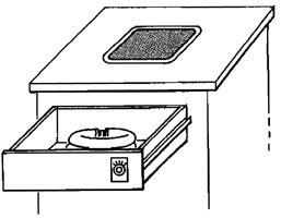
Use the drawer under the counter, or build in a box to hold the fluorescent light fixture. The inside should be painted white to give an even distribution of light.
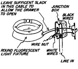
Wire the light using either a regular on-off switch, or a dimmer switch made for fluorescent lights. Mount the switch on the front of the drawer where it will be within easy reach. The junction box for the connection should be under the counter and out of the way. Be sure the line running to the drawer has sufficient slack in the wire to allow you to open the drawer to change the tube when necessary.
Mounting the Enlarger
Normally when you purchase an enlarger, it comes mounted to a wooden or composition baseboard. With minimal effort, you can make improvements in two significant areas: reducing vibrations and increasing the size of prints that can be made.
Reducing Vibration
The sharpness of an enlarged print depends on the sharpness of the camera and enlarging lenses, the type of film used, and the shutter speed or firmness of support used at the time the picture was taken. A factor quite often overlooked is the steadiness of the enlarger at the time the enlargement is made. There is vibration in every enlarger column. This vibration is either picked up from the surrounding environment (such as passing trucks, trains, or kids running in the apartment above the darkroom), or it is induced when you make adjustments to the enlarger while preparing to make a print. Because the enlarger acts as an upside-down pendulum, the vibrations picked up by the base are magnified by the time they reach the enlarger head perched on top of the column.
Since all enlargers, regardless of manufacturers’ claims, are subject to vibrations, the true science should be applied to reducing vibrations or damping them out of the system as far as possible. As long as the column is not oscillating at the time the print is made, the image will be sharp. Part of the damping of the vibrations will be a result of good design on the part of the enlarger manufacturer. The rest depends on where you use the enlarger and how you mount it. The best design in the world will not make an enlarger steady if it is used on an unstable base.
The Pendulum Effect
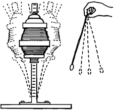
The Pendulum Effect. The enlarger column acts as an inverted pendulum. The vibrations that are picked up by the baseboard are magnified as they go higher up the column. The column will no longer act as a pendulum if the top of the column is supported. This would be the same as holding the bottom of a pendulum and preventing it from swinging.
Damping Vibrations
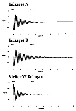
Damping Vibrations. Contrary to what you might think, making an enlarger column more rigid (or stiff) will not help to dampen out the vibrations faster. In fact, a stiff column will only vibrate at a higher frequency, which makes vibrations last longer. These graphs show how the Vivitar IV enlarger, by using a more flexible column, actually dampens vibrations faster than a more rigid enlarger would.
Eliminating Vibrations
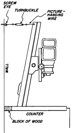
Eliminating Vibrations. The enlarger can be made more steady, giving sharper prints, by attaching the top of the column to a wall or other very solid surface. Be careful, however, since this will not help, and in fact can make things worse, if the wall is not solid and stable. Buy some picture hanging wire, a screw eye, and a small turnbuckle in the hardware store. Cut the wire into two lengths and attach to either end of the turnbuckle. Now screw the screw eye in the wall directly behind the enlarger and fasten one of the wires to it. Fasten the other to the enlarger (you may have to drill a hole for it). Now tighten the turnbuckle just enough to put pressure on the enlarger column. Too much pressure will distort the column, so be gentle.
If you want the enlarger farther out from the wall, insert a block of wood of the necessary length behind it. This will keep the enlarger from moving backward as the turnbuckles are tightened.
Increasing Print Size
The major factor that determines how large a print you can make with a given lens/film format combination is the distance between the negative and the paper on which the print is being projected.
Most enlargers are capable of making prints up to 11” × 14” on the baseboard, and longer columns are also available with options allowing prints as large as 16” × 20” to be made. In either case, larger print sizes can be made by wall-moundng the enlarger.
Wall-mounting the enlarger is usually done in conjunction with building an adjustable enlarger baseboard. This increases the range of print sizes that can be made conveniently. The following pages illustrate how to build one of these units.
Most enlarger manufacturers make wall-mount units for their enlargers that are relatively inexpensive. You can also build your own, provided you are handy with tools. Before doing so, it is wise to check how steady the wall in the room is. Exterior walls are generally well-made since they are designed to carry the weight of the house. Interior walls are either load-bearing or not; the ones that are not load-bearing are usually less steady. If possible, use an exterior wall or an interior load-bearing wall to mount the enlarger. Generally, shorter walls will be more stable than taller walls, because their supports are closer together.
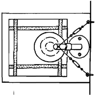
Using Two Turnbuckles. A single column enlarger can be made even steadier by using two sets of turnbuckles.
Wall-Mounting the Enlarger
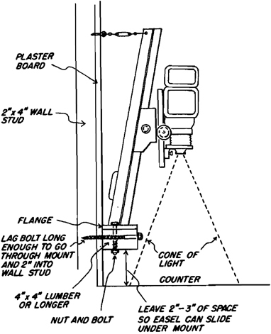
Wall-Mounting the Enlarger. The first step in mounting the enlarger is to devise a support tp which it can be fastened. The type of support will vary, depending on the type of flange used to bolt the enlarger to its base. The easiest support can be made from a few feet of 4” × 4” lumber from a local lumber supply store. If the flange on the enlarger is larger than 4” buy a 6” × 6” or larger piece of wood. This can be bolted to the wall studs (not to the plaster or plaster board) with long “lag bolts,” and then the enlarger can be mounted to it. The top of the column should then be supported with turnbuckles and picture-hanging wire to eliminate any vibrations in the column.
Another Wall Mount
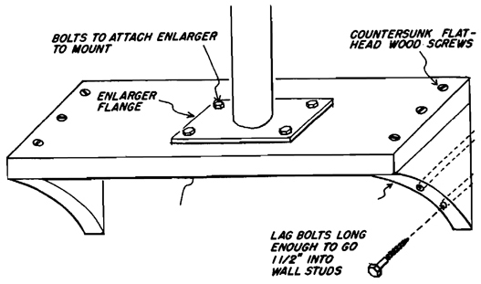
Another Wall Mount. In some cases it may be necessary to build a more complicated support on which to mount the enlarger. If the flange on the enlarger is wider than 6”, it is generally better to use a 2”-thick plank, wide enough to accommodate the enlarger-mounting flange. This plank can then be mounted horizontally to the wall by cuffing supports for both ends out of the same plank.
Building an Adjustable Enlarger Baseboard
With a given film format/lens combination, the sole determining factor as to what size prints can be made is the distance between the negative and the paper surface. This can be increased by raising the enlarger head up the column, but at some point it can go no farther. In addition, problems with vibration are increased as the head is raised higher.
An adjustable baseboard can be built to allow for greater print sizes. It is essentially a unit that decreases or increases the negative-to-easel distance by raising or lowering the shelf on which the easel rests. The lower the shelf, the greater the size of the enlargement.
Print Sizes
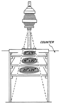
Print Sizes. The enlarger projects a cone-shaped image that grows in size the farther it gets from the enlarger lens. To obtain a larger image, the easel must be placed farther from the lens in a wider section of the cone.
Determinng Shelf Heights
When making an adjustable enlarger baseboard, you should take into account the size of the prints you make most often. The shelf for this print size should be placed at countertop height for maximum comfort. Very much larger print sizes will be lower and very much smaller print sizes higher, but because they are made less frequently, the resulting discomfort is minimized.
Most enlargers will print up to 11” × 14” on the baseboard, and some will go as high as 16” × 20”. Therefore, it is likely that one of these sizes will be the one placed on the shelf at counter-top height.
Keep in mind that if you crop your prints considerably, you may actually be enlarging to 16” × 20” size to obtain the 11” × 14” print you want.
Selecting the Easel Shelf Size
The size of the enlarger baseboard you need is based on the size of the largest easel you plan on using. If you normally print 8” × 10” but occasionally want to print up to 20” × 24”, the baseboard should be designed to handle the easel for a 20” × 24” print in either a horizontal or vertical alignment. This will require a shelf size of at least 28” × 28”; the shelf, side, and back panels, plus the shelf supports, should be cut accordingly. Be sure to allow for the size of the easel, not the print, plus handling room on either side of the easel.
The shelf can have handles attached to the top side on both sides to make it easier to lift in and out when it’s being raised or lowered.
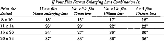
Negative-to-Easel Distance
Negative-to-Easel Distances. When making an enlargement from a given negative size, the significant factor determining the size of enlargement that is possible is the distance between the negative and the paper on which the image is projected. Secondary factors that influence maximum print size include increased exposure times, reciprocity failure, loss of contrast, and vibration, but for the moment these will be discounted. This table is designed to give you the approximate distance your negative must be from the paper (easel surface) to obtain a specific print size from the most common film format/enlarger lens focal-length combinations. Decide first what print sizes you want to make. Once that size is established, you can determine what range of distances has to be obtained for the minimum and maximum sizes you want to print. If, for instance, you want to make both 5” × 7” and 20” × 24” prints using a 50mm lens and 35mm film, you must be able to increase the distance between the negative and the easel from a minimum distance of approximately 11” to a maximum distance of 36”, or a total range of 25”. Some enlargers can accommodate this range on the baseboard that comes with the enlarger, but on most, you will either have to project the image on the floor, tilt the head to project on a facing wall, or build an adjustable enlarger baseboard.
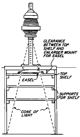
How to Build It

How to Build It. Cut the shelf and three side panels from a sheet of 3/4” plywood. The back panel should be cut the same width as the frames, plus 1/8” for ease in getting the frames in and out. The side panels should be cut to the same length plus an additional 3/4”, because they will be screwed into the 3/4”-thick back panel. The back rails should be the same width as the back panel. The side rails should be only long enough to be flush with the front of the unit and with the back rails.
Assemble the three large plywood panels, and then measure and install the back and side shelf supports.
Mount a plank at least 2” thick to the top back of the unit as a support on which to mount the enlarger. The first (top) shelf support should be low enough to provide clearance for the easel to fit between the top shelf and the board on which the enlarger is mounted, otherwise you may not be able to center the image on the easel.
Assembled Unit
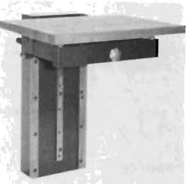
Fotar Enlarging Table. This enlarging table from Colenta America is extremely sturdy. It’s expensive, but a butcher-block baseboard and ease of operation would make it worthwhile for someone making a great many prints and changing print sizes frequently.
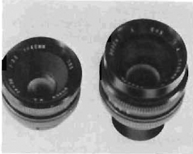
Special Lenses. There are also special enlarging lenses that can be used to increase the size of the prints you make with a given negative-to-easel distance. Wide-angle and zoom enlarging lenses are available, although those of high quality are very expensive. For more on enlarging lenses see Chapter 8.
Air Quality
The quality of the air in the darkroom directly affects both the quality of work done there and the health and enjoyment of the photographer. Several aspects of darkroom air have to be considered.
Humidity
The ideal darkroom humidity is between 45 and 50 percent. In some parts of the country, this is easy to maintain without controls, but sometimes control is an absolute necessity. Air that is too damp will rust equipment and make it perform inaccurately; air that is too dry will create static electricity problems and increase problems with dust. A dehumidifier can help a damp room (a side benefit is that the water run off from the dehumidifier can be bottled and used as distilled water for negative processing). A room that is too dry can be corrected with the addition of a humidifier.
Temperature
The ideal darkroom temperature is approximately 68°F, the temperature at which most photographic chemicals are used. If temperatures vary considerably, time is spent worrying about water baths, comfort, and the timing of the various developmental processes. To control the temperature, you can install heaters or air conditioners. Air conditioners are especially useful because they will also filter and dehumidify the air as they are cooling it. If you use an air conditioner, try to have the air flow from the dry side to the wet side, so that steam and vapors rising from the sink are not carried over to the dry side. Be sure to buy an air conditioner that can operate on fan only, so that the room can be ventilated without being cooled.
Ventilation
The minimal controls required in a darkroom concern air flow and turnover. The air in the darkroom must be changed every six to eight minutes for comfort. To make this possible a fan and vents must be installed. The fan should always be filtered, and the air stream should enter the darkroom from the dry side. Outlet vents should be over the sink on the wet side. This arrangement increases the pressure in the room, so that unfiltered air from outside does not carry dust into the darkroom. The flow from the dry to the wet side keeps the vapors from the sink contained, and the outlets over the sink provide a way for the air to be carried from the room. All vents and fans should be light-proof.
Dust
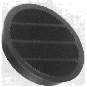
Dust must be kept out of the room, or removed if any dust seeps in. The best device is an electrostatic air cleaner to filter particles out of the air.
How to Find the Size Fan You Need
Air in the darkroom should be changed every six to eight minutes. To determine the size fan needed you have to know the number of cubic feet in the room. Fan capacities are rated in cfm (cubic feet per minute). To determine the cubic feet in your darkroom, measure the room’s width, length, and height. Multiply these dimensions to give you the total cubic feet in the room. Divide that figure by 6 to determine how many cubic feet per minute the fan must move if it is to change the entire room every six minutes. Example: if the room is 8’ wide, 10’ long, and 7’ high: 8 × 10 = 80; 80 × 7 = 560 cubic feet. 560 divided by 6 = 93 cubic feet per minute. The fan should be approximately 100 cfm rated.
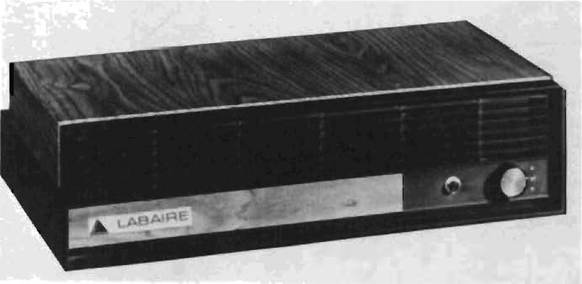
Electrostatic Air Cleaner. Eliminating dust from the darkroom can be a full-time job. If you don’t get it out of the air, you have to get it off of the negatives. If you don’t get it off of the negatives, you have to spot the prints. If dust is a problem, you can install either a wall-mounted or tabletop electrostatic air cleaner. It works by charging dust particles so that they will adhere to a collector with an opposite charge. Because the dust builds up on these collectors, you should also consider their ease of cleaning. This model collects particles down to .01 microns. The collecting screen is washable.
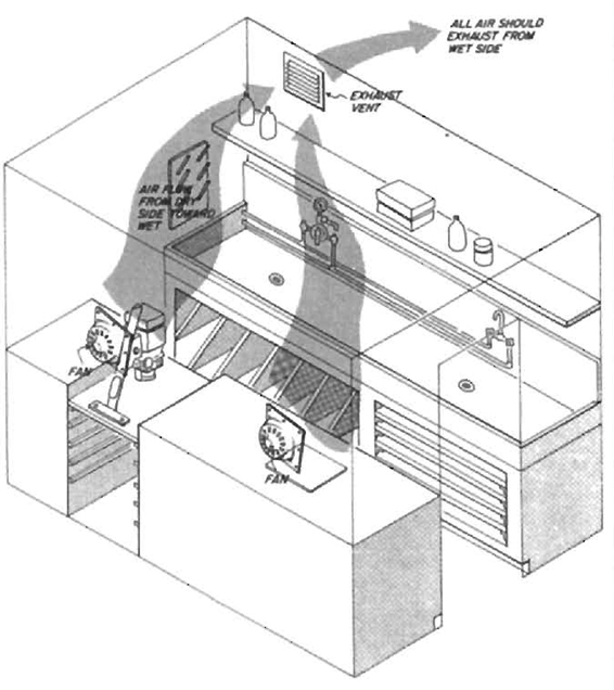
Darkroom Air Flow. If the fan is mounted to blow into the room, the fan should be installed on the dry side of the darkroom with the vents on the wet side. The air entering the room will keep it at a positive pressure, and air will flow out of the cracks in the room, which keeps the dust out.
Should you decide to use the fan as an exhaust fan blowing air out of the room, it should be mounted on the wet side, so that the moist air from the sink and chemicals exit immediately without being distributed throughout the room.
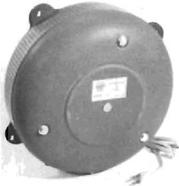
Ventilator Fan. Special light-proof fans are baffled to prevent light from leaking through the fan opening. They are often hard to find, so most photographers just use a regular bathroom fan and build a light-proof baffle around It themselves. In some cases, you may be able to vent the fan into a dark attic or basement and avoid the need for a baffle entirely.
Exhaust Vents. Darkroom vents should be light-proof. Spiratone supplies these 4”-diameter “Darkroom Breather” vents.
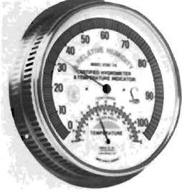
Humidity and Temperature Indicator. This combination humidity and temperature indicator is a good item for the darkroom. Then again, perhaps ignorance is bliss.
Light-Proofing
Light-proofing is essential to prevent light-sensitive film and paper from fogging. Many prints lack contrast between shadow and highlight areas because the paper or film was exposed to non-imaging light that made the contrast muddy. This effect is sometimes so slight that it can be discovered only by running a proper test, but once comparison prints are made, the loss of quality will become immediately apparent.
Film, with its higher speed, is much more susceptible to light than is enlarging paper; therefore, a room in which printing is done need not be as light-proof as a room in which film is handled. A kitchen or other temporary darkroom can usually be light-proofed sufficiently to make prints (or you could print only at night), and film can be loaded into reels and placed in daylight tanks inside a changing bag. To be sure a room is light-proof enough to print, first stand in it with the lights out for at least five minutes so your eyes have a chance to adjust completely. If you then cannot see a plain white paper held against a dark background the room should be safe. A few small leaks around doors and windows are safe if they are not near the enlarger or processing trays or paper cutter. Such leaks can be eliminated, however, with aluminum foil crumpled and stuck into holes or taped in sheets over larger openings. Larger areas can be covered with light-proof cloth or black garden plastic and tape.
Windows
Windows can be light-proofed using special shades made specifically for the purpose. These shades are relatively expensive but are convenient if the darkroom must be used for other purposes. A somewhat less expensive method is to use light-proof cloth fastened to the wall or window frame with velcro tape, which is available in sewing supply stores. One part of the tape can be permanently mounted to the window frame and the other sewn to the cloth. The two can then be stuck together and pulled apart as need be. When the cloth is not being used, it is easy to fold and store.
A third method is to use masonite paneling and either velcro tape or screws to hold it in place. These panels can be made cheaply and are totally light-proof.
Windows facing sources of subdued light can be covered with red plexiglass to act as a safelight. Always run a safelight test after doing this. If paper fogs, use a double thickness of plexiglass.
The cheapest and easiest method of all is to paint the windows black, but this works only if you never want light through them.
Doors
The ultimate door is a revolving one, but most people cannot afford the expense. An alternate solution is a light trap, which is inexpensive but does require a lot of floor space. Several possible designs are shown in Chapter 4. These entryways are ideal, because they allow people and air to circulate freely without light entering the darkroom. Light traps should not face a bright light source because reflections can work their way into the darkroom. If this is impossible to avoid, the entrance can be covered with a hanging cloth with a chain or weights sewn in the bottom to hold it down.
Light-Proofing a Shade
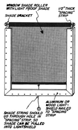
Light-Proof Shade. These are perfect for the room that must serve more than one purpose. Release the latch and ZAP … the light is back in the room and the shade has disappeared. Reasonably priced, custom-made models are available from Draper Shade Co.
Light-Proofing with Panels
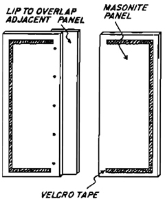
Light-Proofing with Panels. Use either one large panel or a series of smaller panels fastened to the wall or window frame with velcro tape. This will allow for easy installation and removal. Handles on the top and bottom of each panel make the chore even easier.
Light-Tight Drawer or Paper Safes
A place to store paper when the lights are on is a real convenience. It is time-consuming and bothersome to work directly from the paper box, especially when large numbers of prints are being made. Better to build a light-proof drawer or buy a paper safe.
Vents, Fans, and Heaters
All equipment installed in the walls of a darkroom should be light-tight. Some vents and fans are made specifically for darkroom use. If you choose to use a regular fan, a louvered box can be made to cover it making it light-safe. You should also remember that some space heaters have radiating coils that can emit sufficient light to fog paper. If you plan to use one that emits a glow, be sure to run the safelight test given on page 112. If the darkroom is located near the furnace or hot water heater, make sure that, if they suddenly turn on, the light emitted won’t fog your prints.
Light-Proof Drawer
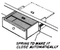
Light-Proof Drawer. A light-proof drawer makes the printing process a great deal easier. The one illustrated here has a top, sliding in grooves, that closes automatically when the drawer is closed. The piece of wood on the top slide hits the piece of wood on the bottom of the counter top and closes the interior lid. The springs attached between the drawer and the wall ensure that the drawer closes automatically. All of the interior surfaces of the drawer should be painted a flat black to reduce reflections.
Light-Proofing a Door
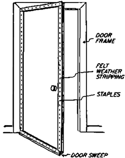
Light-Proofing a Door. A light-proof door still has to open and close. You can light-proof the door, and still allow it to be usable, with inexpensive weather stripping and a rubber door-sweep available at any hardware store.
Light-Proofing a Window.
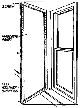
Light-Proofing a Window. The techniques used to light-proof a window range from painting it black (which is hard to remove the next day), to just lowering the shades and printing at night. A more flexible method is to cover the entire window with a sheet of masonite (or plywood) edged with felt weather stripping (or foam tape); your room is light-proofed, but you can easily remove the masonite whenever you want.
Changing Bag. Many darkrooms are safe to print in but have too much light to load and unload film safely. The solution is to use a changing bag that is completely light-proof. Film can be loaded onto developing reels and placed in a daylight tank.
Unique Solution
Because of the high cost of energy, a variety of ingenious energy-saving interior storm windows are on the market. Many use plastic channels that attach to the window frame and hold a rigid or flexible vinyl storm window. In order to light-proof using these products, you will have to locate a light-proof, rigid or flexible vinyl to fit the channels. Masonite will usually fit the rigid models, and two layers of 4 mil. garden plastic should work with the flexible models. These units are easy to use and have the added benefit of conserving energy. Most of them are made by small companies and a variety of types are manufactured, so visit a few different building supply stores to find out what is available.
Those Added Comforts
It’s rare that you will have a reason to fill your sink with champagne bottles as Gil Amiaga did for the opening of his new studio. There are, however, small things that can be added to a darkroom to make it a more pleasant place to be when all of your listless friends are lying on the beach.
Phone
To avoid the dilemma of having to hurry up with a print or miss a call from your editor, an extension phone permanently installed in the darkroom can save time and pictures. It’s also a good way to keep in touch with the outside world when performing some of the more boring aspects of your work.
Heaters
Adequate heat in the darkroom isn’t only for your comfort, but also helps keep chemicals at the proper temperatures when processing. If you can keep the darkroom temperature at 68°F (20°C), it greatly simplifies temperature regulation. You need a heater that doesn’t emit any light that could fog your film and paper. Radiant heaters with quartz or electric coils are out, because they light up when in use. A large variety of models at discount stores have concealed heating elements that don’t emit light. A built-in thermostat is also useful, because it will help keep the room consistently at the right temperature. Be sure your heater has a special mercury switch that automatically turns the unit off if it’s tipped over and a three-prong grounded plug for additional safety.
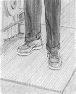
Floor Mats
Standing on a hard floor all day was fine in a nineteenth-century sweatshop, but in a comfortable darkroom it is definitely out. There are commercial floor coverings, such as Ace Core-Lite and Leedal floor mats, made especially for the darkroom. A piece near the enlarger and a strip along the front of the sink will usually suffice if you don’t want to do the entire floor.
Stereo
A radio or extension speakers from a good stereo will add a lot to the enjoyment of printing.
Television
Believe it or not, there are photographers who have filters taped over their television sets so they can watch the football game while printing. They have a tendency to get their zone systems confused with zone defenses, but that’s one of the hazards of doing two things at the same time.
Photograph by Gil Amiaga.