
7
Depth of Field
Depth of field is the range of object distances over which objects appear acceptably sharp in a photographic image when viewed at the normal viewing distance. A small depth of field, where objects in front of and behind the plane focused on appear unsharp, is often used to direct the viewer’s attention to a certain part of the photograph and strengthen the perspective, whereas a large depth of field is used where obtaining detail in all parts of the subject is the primary objective. A number of factors including lens focal length, film size, object distance, the f-number used when taking the photograph, and the distance at which the photograph is viewed, determine the actual depth of field obtained in a photograph.
7.1 Resolution of the Eye
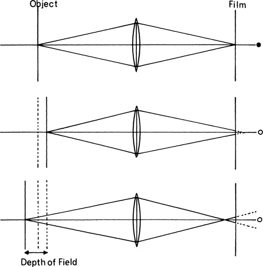
Figure 7-1
Depth of field is the range of object distances over which objects appear acceptably sharp on the print when viewed at the normal viewing distance. The acceptable circle of confusion is the image of a point on an object located at the near or far limits of the depth-of-field range.
Not all parts of a print that appear acceptably sharp at the normal viewing distance will appear equally sharp if the image is examined through a magnifier. When a camera is focused on a given distance (as in copying, for example), that is the only distance theoretically in sharp focus. In practice, however, the two-dimensional subject can be moved somewhat closer to and somewhat farther away from the camera before a noticeable decrease in sharpness occurs. At the near and far positions, each point on the object is imaged as a circle rather than as a point, as illustrated in Figure 7-1, but the eye sees circles smaller than a certain critical size as points. Even in the position of optimum focus, of course, the “point” image is actually a measurable circle due to the effects of lens aberrations, diffraction, and other factors, but with a good-quality lens, this circle is small in comparison to the circle that determines the limits of depth of field.
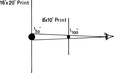
Figure 7-2
Depth of field does not vary with print size provided the viewing distance changes accordingly.
The largest circle that appears to the eye as a point is referred to as the acceptable circle of confusion. A diameter of 1/1000 in. is sometimes considered to be the largest circle that will appear as a point in a print viewed at a distance of 10 in. If the print is a contact print, the same criterion applies to the negative; but if the print represents a two-times enlargement from a smaller negative, the acceptable circle of confusion on the negative is one-half as large as it is in the print, or 1/200 in. The degree of enlargement of the negative has no effect on the depth of field provided the image is not cropped. Although the circle of confusion increases at the same rate as the magnification of the image and eventually will exceed 1/100 in., the viewing distance normally increases in proportion to print size so that the depth of field will remain essentially the same over a wide range of print sizes (Figure 7-2). For photographs that may be examined critically rather than casually, but at the normal viewing distance, the acceptable circle of confusion will be somewhat smaller than 1/100 in. in diameter at a viewing distance of 10 in.—1/167 in. is considered appropriate.
7.2 Viewing Distance and Cropping
Viewing a print from a shorter distance than the diagonal of the print causes those parts of the image that appeared sharp at a normal viewing distance but were situated close to the near and far limits of the depth of field to now appear less sharp. The effective depth of field has been decreased just by looking at the print from a closer position even though the print remains physically unchanged. Cropping an image reduces the depth of field in a similar way. If a 16 × 20-in. print is trimmed to 8 × 10 in., observers will tend to view the cropped print at approximately one-half the distance of the original print. Enlarging only a section of a negative produces exactly the same result.
One important advantage of view cameras and single-lens reflex cameras over other types is that the depth of field can be seen on the ground-glass image, making it unnecessary to refer to tables, scales, or graphs. Unfortunately, the image is not always bright enough to enable the photographer to see the limits of the depth of field clearly, especially when the lens is stopped down. It is worthwhile to examine a comprehensive depth-of-field graph, as we will do later, to observe the effects some of the variables have on depth of field. A depth-of-field graph or table for a lens is accurate for only one film size. Using the lens with a different-size film is the same as altering the cropping and the viewing distance.
7.3 Depth-of-Field Controls
It is important for view camera users to be familiar with the factors that affect depth of field and to understand the extent of the change in depth of field that each of these factors produces. There are three basic controls over depth of field—relative aperture, object distance, and focal length.
Relative Aperture

Figure 7-3
(Top) Stopping down reduces the size of the circle of confusion for an object point closer than the point focused on. (Bottom) Depth of field increases as a lens is stopped down. The circle of confusion for object point B with the lens stopped down is the same as for object point A with the lens wide open.
Varying the relative aperture, or f-number, is usually the most convenient method of controlling depth of field, and the relationship between depth of field and f-number is simple. As a lens is stopped down, the angle of the cone of light behind the lens from a single object point is decreased, and the circle of confusion formed where the film intercepts the cone of light is reduced in size (Figure 7-3). Thus, object points in front of and behind the plane focused on, which appear unsharp at a large aperture, may appear acceptably sharp when the lens is stopped down. The depth of field increases in direct proportion to the f-number, so that stopping a lens down from f/8 to f/16 doubles the depth of field. The relationship between depth of field (D) and f-number (F-N) can be expressed as follows:
To illustrate application of the formula, if a depth of field of 6 in. is obtained with a lens wide open at f/5.6, how far must the lens be stopped down to obtain a depth of field of 24 in.?

We also can observe the effect of stopping a lens down all the way. If a lens has a range of f-numbers, from f/4.5 to f/45,
and the depth of field will be increased to 10 times the original value by stopping the lens down.
Figure 7-4
Since depth of field varies in proportion to the object distance squared, photographs made at a scale of reproduction of 1:1 and larger tend to have a shallow depth of field.
Altering the aperture is not always the complete answer to depth-of-field problems. More depth may be desired than can be obtained at the smallest aperture, or possibly less depth is wanted than is produced at the largest opening. Also, the f-number selected on the basis of depth of field may require an unacceptable exposure time.
Object Distance
Depth of field increases at a rapid rate as the object distance increases. This is evidenced by the difficulty experienced in obtaining sufficient depth of field on photomacrographs of three-dimensional objects, where the required depth of field may be only a fraction of an inch. At the other extreme, a lens focused for a longer object distance may produce a depth of field that extends from infinity to within a few feet of the camera. The relationship between depth of field (D) and object distance (U) is

Thus, doubling the object distance increases the depth of field fourfold, tripling the object distance increases the depth ninefold, and so forth. The differences in depth of field with very small and very large object distances are dramatic. When the camera is at a distance of two focal lengths or less from the subject, the depth of field at a large aperture may appear to be confined to a single plane (Figure 7-4).
The camera position in relation to the subject is usually determined on the basis of image size and perspective, but situations are encountered where depth-of-field requirements are important enough to justify modifying the object distance. This is especially true when stopping the lens down does not produce sufficient depth of field. Increasing the object distance produces a net gain in depth of field even though the image is cropped in printing to correspond to the image produced at the closer camera position. The increase in depth of field will not be as dramatic when the negative is cropped, however, as indicated by the absence of the square symbol in the relationship:
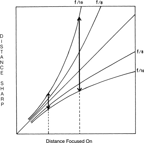
Figure 7-5
Depth-of-field graph, showing the results of changing object distance and f-number.
Changes in depth of field with the two controls considered so far, f-number and object distance (without cropping), are illustrated in the graph in Figure 7-5. The distance focused on is represented by the horizontal axis and the 45° straight line, and the near and far distances that appear sharp are represented by a pair of curved lines for each designated f-number and the vertical axis. The depth of field is indicated for two different object distances at f/16 by the lengths of the vertical arrows. As observed previously with the depth-of-field object-distance formula, the depth of field is increased fourfold when the object distance is doubled. Relative depth in front of and behind the plane focused on is also shown by the graph, and the fallacy of the 1/3 rule can be observed. According to the 1/3 rule, twice as much depth lies behind the plane focused on as in front of it. Actually, when the depth of field is small (at large apertures and short object distances), the depth of field is distributed almost equally in front and back. As the depth of field increases, a larger portion of the increase goes to the back. This imbalance in depth becomes most obvious when the depth of field extends back to infinity. Maximum depth of field resulting from changing object distance is obtained when the lens is focused on the nearest distance that will extend the depth of field to infinity. The distance focused on in this situation is known as the hyperfocal distance, and the near distance that appears acceptably sharp will be midway between the plane of sharpest focus (at the hyperfocal distance) and the lens (Figure 7-6). Thus, to obtain the maximum depth of field when photographing a scene that includes a distant object, the lens should be focused as close as possible while rendering the distant object acceptably sharp. Hyperfocal distance may also be defined as the nearest distance that appears acceptably sharp when the lens is focused on infinity.
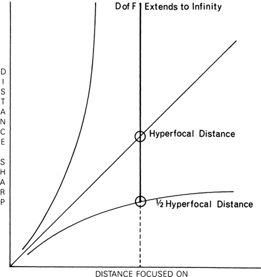
Figure 7-6
Focusing a lens on the hyperfocal distance produces a depth of field from infinity to one-half the hyperfocal distance.
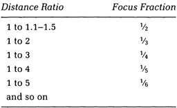
There are more precise procedures for determining the optimum distance to focus on to obtain equal sharpness for foreground and background objects than just deviating from the 1/3 rule as discussed previously. The ratio of the distances from the camera to the nearest and farthest objects for which sharpness is desired determines the fraction of the distance between the objects to focus on. When the far-object distance is twice the near-object distance, for example, the 1/3 rule applies. This and other distance ratios are:
Other ways of determining the optimum distance to focus on are discussed in Section 7.7, “Depth-of-Field Scales.”
Focal Length
An inverse relationship exists between depth of field and focal length. Although we can generalize that long focal length lenses produce less depth of field than short lenses, we must consider two situations in establishing a mathematical relationship. In the first situation, the film size remains constant as the focal length is changed; and in the second situation, the film size and focal length both change at a corresponding rate.
When the film size is kept constant, the depth of field varies inversely with the focal length squared, or
Thus, the depth of field increases at a very rapid rate as the lens focal length is decreased, as illustrated by the fourfold increase in depth that results when the focal length is halved. If a constant image size must be maintained, however, it will be necessary either to move the camera closer with the shorter lens or to enlarge and crop the negative in printing. Moving the camera closer will completely destroy any increase in depth obtained by using a shorter lens. In situations involving simultaneous changes in object distance and focal length, the depth of field will vary inversely with the scale of reproduction; and there is no advantage (with respect to depth of field) in altering these factors if the scale of reproduction remains constant.
Depth of field can be altered with focal length while maintaining a constant image size on the print by keeping the camera in one position and compensating for the differences in image size on the negatives in printing. If the same film size is used with two different focal length lenses, the negative made with the shorter lens must be both enlarged and cropped. This is essentially the same as using a smaller-format camera with a proportionally shorter focal length lens, in which case the negative would have to be enlarged but not cropped. In both situations the enlarged photographs made with the shorter focal length lenses will have a larger depth of field than the photograph made with the longer focal length lens in the proportion indicated by the following formula:
When more depth of field is needed than can be obtained by stopping a lens down with a given camera, therefore, either of two methods may be used. First, move the camera farther from the subject without changing the lens. Enlarge the negative and crop in printing. The perspective and overall definition may be affected by these changes. Second, keep the camera in the same position and use a shorter focal length lens. Enlarge the negative and crop in printing. The perspective will not be affected, but there may be some loss in overall definition.
A special problem is encountered when the end product is a color transparency rather than a print. If the depth of field is insufficient when the lens is stopped down and the nature of the subject is such that the camera swing and tilt adjustments cannot be used to provide the necessary depth, the photographer has little choice but to accept the inadequate depth of field or the smaller image resulting from a larger object distance or use of a shorter focal length lens.
7.4 Swings and Tilts, and Depth of Field
The effect of swinging or tilting the camera lens or back on depth of field can be observed in the graphs of Figures 7-5 and 7-6 since the camera is actually focused on a series of object distances that vary from side to side with the swings and from top to bottom with the tilts. The scene in Figure 7-7 is ideally suited to use of the lens tilt (or back tilt) to obtain overall image sharpness. The closest part of the scene has little depth and therefore requires little depth of field whereas the mountains, which are very high, are far enough away for the depth of field at that distance to be more than is necessary to make them appear sharp.
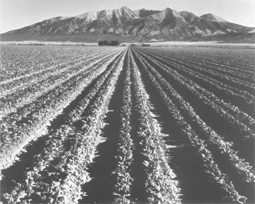
Figure 7-7
The top of the lens board can be tilted forward (or the back in the opposite direction) to include all parts of this scene within the depth-of-field pattern without stopping the lens down. With a camera that lacks tilt adjustments, it would be necessary to focus on the hyperfocal distance and then stop the lens down far enough to include both the foreground and the mountains in the background.—John Johnson
Stopping a lens down increases the depth of field, but the shape of the depth-of-field area is drastically different when swing or tilt adjustments are used than when they are zeroed. Since the depth of field increases with object distance, the depth of field will be uniform over the entire width of a scene with the swing adjustments zeroed. Depth of field will vary from side to side, however, when a swing adjustment is used to change the angle of the plane of sharp focus, as shown in Figure 7-8, where the solid lines in object space represent the plane of sharp focus and the dashed lines represent the near and far depth-of-field limits. The camera is actually focused on different object distances when a front or back swing adjustment is used, and since depth of field increases with object distance, it will vary from side to side.
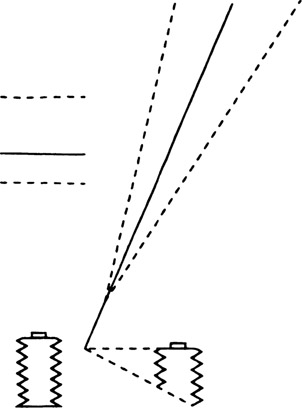
Figure 7-8
Shape of the depth-of-field area with the front and back swing adjustments zeroed (left) and with the back swung (right).
The unsymmetrical depth-of-field patterns produced when the swing and tilt adjustments are used to alter the angle of the plane of sharp focus can be useful in many picture-taking situations involving three-dimensional subjects. Two adjacent walls of an interior, for example, can be imaged sharply by swinging the lens or back, so that the plane of sharp focus in Figure 7-9 includes point A, the nearest point on the wall to the left that is to be included in the photograph, and point B, a point in the center of the width of the back wall that is to be included. The dashed lines indicate the depth-of-field limits. A corresponding subject using a tilt, rather than swing, adjustment is shown in Figure 7-10. By tilting the lens or back so that the plane of sharp focus includes point A, the nearest point on the ground that is to be included in the photograph, and point B, a point about halfway up the vertical dimension that is to be included, everything between the dashed lines will appear sharp in the photograph.
With objects that have equal depth and height, little is gained by altering the angle of the plane of sharp focus with swings or tilts. If the back has been tilted to prevent convergence of vertical subject lines, as shown in Figure 7-11(A), the photographer should keep in mind that this has also altered the angle of the plane of sharp focus. When the lens is used to focus the image, the plane of sharp focus moves up and down on the subject rather than from front to back, as occurs with the adjustments zeroed. Consequently, rather than focusing on an appropriate point between the front and back on the top surface, it may be necessary to focus at an appropriate point between the top and bottom of the front surface if the entire object is to be included between the depth-of-field limits when the diaphragm is stopped down. A technique used by some photographers when it is difficult to know where to focus on a subject is to move the focusing standard forward and backward to determine the minimum and maximum extensions that will produce sharp focus on any part of the subject, place a pencil mark on the camera bed for each of the two positions of the focusing adjustment, and then set the focusing adjustment halfway between the two marks (Figure 7-11(B)). With cameras that have a linear scale on the bed, the scale markings can be used for this purpose.
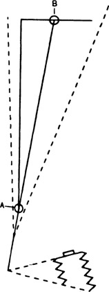
Figure 7-9
Use of the swing back to obtain a sharp image of two adjacent walls.
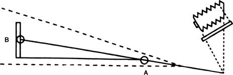
Figure 7-10
Use of the tilt adjustment to obtain a sharp image of the horizontal foreground and the vertical object.
Figure 7-12 illustrates a subject where the tilts and swings are of little use in increasing the depth of field, and the best approach
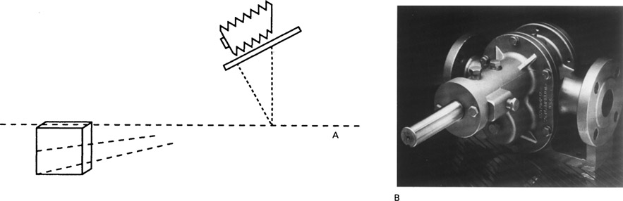
Figure 7-11
(A) Change in the plane of sharp focus as the camera focus is changed when the lens board and film plane are not parallel. (B) Type of subject where, after tilting the back to the vertical position for image shape, the optimum focus can be determined by marking the near and far limits of the focusing standard that produce sharp focus on any part of the subject and then setting the focusing standard halfway between the two marks.—Len Rosenberg
Figure 7-12
An example of a scene where little is to be gained by altering the angle of the plane of sharp focus with the tilt or swing adjustment.—Neil Montanus
is to focus on an appropriate distance so that as the lens is stopped down, the near and far depth-of-field limits are located at the near and far parts of the subject that are to appear sharp.
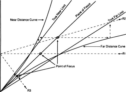
Figure 7-13
Graphic representation of the shape of the near and far limits of depth of field with the subject plane of focus at an oblique angle.—Courtesy of ImageQuest Corporation, Denver, Colorado
7.5 Depth-of-Field Limits
When the front and back of a view camera are in their normal or zero positions, the plane of focus and the near and far limits of the depth of field are planes that are parallel to each other and to the lens board and film planes. When the back or front of the camera is tilted or swung to satisfy the Scheimpflug rule with a receding subject plane, the camera is simultaneously focused on a continuum of different object distances. Since depth of field increases approximately with the square of the object distance over a large range of distances, it might be assumed that the near and far depth-of-field limits would be curved, like the near and far limit lines with increasing distance, on depth-of-field graphs. The drawing in Figure 7-13 illustrates that the near and far limits are planes rather than curved surfaces because the near and far object points associated with a given point of focus must be on the same central ray of light to the lens as the point of focus, rather than on a straight line parallel to the lens axis as when the camera adjustments are zeroed. The near and far limit planes meet the plane of sharp focus at a distance of one focal length in front of the camera lens. Figure 7-14 shows the change in the angles of the near and far depth-of-field limits as the lens is stopped down.

Figure 7-14
Changes in the angles of the near and far limits of depth of field as the camera lens is stopped down. The point of convergence is one focal length in front of the lens plane.
7.6 Depth-of-Field Tables
Depth-of-field tables are published by camera and lens manufacturers and can be found in some photography books. Typical tables specify the near and far limits of depth of field for a range of object distances and f-numbers. Unfortunately, there has been a lack of agreement on the method of specifying the diameter of the acceptable circle of confusion for the near and far limits on different tables—as a specified fraction of the focal length of the lens or as a specified size circle on the negative—and also a lack of agreement on the size of the acceptable circle of confusion on the photograph at a standardized viewing distance.
A diameter of 1/167 in. is considered appropriate for professional photographic purposes for a photograph viewed at a distance of 1 0 in. It is assumed, for depth-of-field calculations, that photographs are viewed at a distance equal to the diagonal dimension, such as 10 in. for a 6 × 7 ½-in. print. Since a 4 × 5-in. negative must be enlarged approximately 1.5 times to make this size print, the diameter of the acceptable circle on the negative is found by dividing the diameter of the circle on the print by the magnification. Thus, 1/167 in. on the print corresponds to 1/250 in. on the negative.
7.7 Depth-of-Field Scales
For many years small-format roll-film cameras have had depth-of-field scales on the lens barrel or camera body, a feature now being adopted by view camera manufacturers. A typical view camera scale consists of a circular band containing a scale of f-numbers located on the rear focusing knob (Figure 7-15). The camera is first focused on the most distant point for which sharpness is desired, and the scale is rotated to the zero setting. The camera is then focused on the closest point for which sharpness is desired—the scale rotates and a mark indicates the f-number required to obtain the desired depth of field. To obtain the optimum focus, the focus knob is turned back until a position two stops larger than the specified f-number lines up with the index mark. Since the distances between whole stops form a ratio scale (rather than an interval scale as on rulers), the position of the back standard for optimum focus is halfway between the positions for near focus and far focus. On view cameras lacking this feature, the optimum position can be determined by marking the near and far positions of the back standard on the camera bed or using the rear focusing scale, if there is one, and then setting the back standard halfway between the marks, but another method must then be used to determine the f-number that will provide the required depth of field.
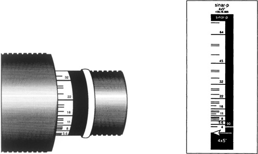
Figure 7-15
(Left) A depth-of-field focusing scale on the rear focusing knob of a Sinar view camera. (Right) One of four different scales that are substituted when film formats are changed.—Sinar Bron
Depth-of-field scales on the focusing knob of view cameras remain accurate when longer and shorter focal length lenses are substituted for the normal lens but not when the camera is focused on close objects. One camera manufacturer provides four interchangeable bands that are matched to four different scale-of-reproduction ranges. Substituting a camera back that accommodates a smaller or a larger film format also requires a change in the depth-of-field scale.
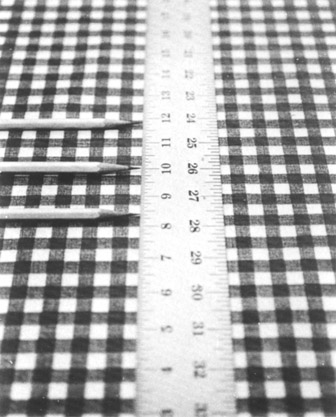
Figure 7-16
Depth-of-field scales and tables can be checked by photographing an object at an angle with markers placed at the point of focus and at the indicated near and far limits of the depth of field. A 6 × 8-in. or larger print should be made so that it can be viewed from the correct viewing distance, a distance equal to the diagonal of the print.
An electronic calculator that determines the position of optimum focus and the f-number required to obtain the desired depth of field is available as an integral part of some view cameras.
7.8 Checking the Depth of Field
It is not difficult to perform a practical test to determine whether the depth of field produced using the settings indicated by a depth-of-field table, camera scale, or electronic calculator agrees with the photographer’s criterion for judging acceptable image sharpness in photographs. One procedure is to photograph a flat surface that has good detail at an angle of approximately 45°—a horizontal angle for a wall or a vertical angle for a floor or tabletop—placing markers at the point focused on and the near and far limits of the indicated depth of field (Figure 7-16). Measurements should be made parallel to the lens axis and from the plane of the lens board. Four more exposures should then be made, stopping the lens down and opening it up one stop and two stops. Uncropped prints should be viewed from a distance equal to the diagonal dimension of the prints, and a comparison of the images will reveal whether the recommended settings were appropriate. Some electronic depth-of-field calculators have incorporated procedures for altering the value of the acceptable circle of confusion used in the calculations.
7.9 Calculating the Depth of Field
Fortunately, photographers seldom need to calculate depth of field when they have tables, scales, or a view camera ground glass to refer to, but depth of field can be calculated using the following four steps:
1. Calculate the hyperfocal distance:
where f is the focal length, F-N is the f-number, and C is the acceptable circle of confusion (in the negative).
2. Find the near-distance sharpness:
where U is the object distance.
3. Find the far-distance sharpness:
Note: An appropriate value to use for C for 4 × 5-in. film would be 1/250 in. (which corresponds to 1/167 in. on a 6 × 7 ½-in. print that would be viewed at a distance of 1 0 in.). All other values should be expressed in inches as well.
7.10 Depth of Focus
Depth of focus is the distance the film plane can be moved without producing a noticeable change in sharpness of the image of an object point, as viewed on the print (or the ground glass) at a normal viewing distance. When focusing a camera on a two-dimensional subject, as when copying, the limits of the depth of focus are established where the size of the image of each object point equals the acceptable circle of confusion (Figure 7-17). Information concerning depth of focus is important to camera and film manufacturers, since this determines the extent of tolerable film buckle and the precision required in the construction of cameras and film holders. Depth of focus provides the photographer with latitude in the precision required in focusing on a single plane.
The actual depth of focus can be determined as follows:
Thus, using 1/250 in. as the acceptable circle of confusion for 4 × 5-in. film and a relative aperture of f/11, the depth of focus is approximately .088 in. (1/11.4 in.). Although photographers may seldom have occasion to calculate depth of focus, this simple formula helps to understand the basic concepts involved in its control.
Four significant relationships involving depth of focus follow:
- Depth of focus increases as a lens is stopped down. This is a direct proportion, as indicated in the preceding formula, so that stopping down from f/11 to f/22 doubles the depth of focus just as it doubles the depth of field.
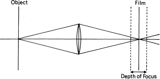
Figure 7-17 Depth of focus is the distance the film plane can be moved before the image of an object point appears unsharp, as viewed on a print at the normal viewing distance.
- Depth of focus increases as object distance decreases. Although the marked f-number does not change as the subject-to-camera distance becomes smaller, the effective f-number becomes larger, and this value must be used in the preceding formula for short object distances.
- Depth of focus is not affected by focal length. At the same f-number, all focal length lenses subtend the same angular cone of light. Note that the term focal length does not appear in the formula.
- Depth of focus increases as the film size increases. The viewing distance and therefore the acceptable circle of confusion increase with negative size.
Depth of field and depth of focus are related, of course, but we notice they do not respond in the same way to changes in object distance and focal length, relationships 2 and 3 above. Freedom in moving the subject within the depth-of-field space or the film within the depth-of-focus space can be used only once for a given photograph. If a subject exactly fills the depth-of-field space, then the film can occupy only one position, and no tolerance remains for the photographer or the camera.