6 |
Digital TV by Terrestrial Transmitters |
| CHAPTER |
FIGURE
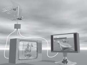
6.1
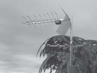
Terrestrial digital TV use the traditional TV antenna.
For decades, terrestrial TV was the only way to watch TV. The only exception was MATV systems which could more or less be regarded as an extension of the terrestrial transmitters.
Terrestrial TV is the oldest way of distributing TV and for this reason, all TV sets are equipped to receive these signals without any access to either cable TV networks or satellite dishes. Terrestrial TV is still very popular today. In an astounding way, terrestrial transmissions have been able to withstand the competition from cable and satellite. Even viewers who have access to satellite TV still use terrestrial TV as a complement for reception of the basic free to air channels.
There are even technical advantages in terrestrial TV compared to the other ways of distribution. On top of no need for a cable TV connection, the terrestrial reception is not affected by bad weather conditions such as snow or heavy rain. In other words, terrestrial TV is a very reliable way of distributing TV.
Since the TV signal contains a large amount of information, the analog signals require a lot of bandwidth and rather high frequencies are required for distribution. For this reason, high towers were built to hold the transmission antennas.
The same thing applies to FM radio being transmitted in the range 87–108 MHz. Before the 1950s, when FM radio and television was introduced, lower towers and wires were used for distribution of AM radio in the long- and medium-wave frequency bands. Now 300 m (1,000 feet) towers were introduced to cover an area up to about 50 km (30 miles) or away from the transmission site (see Figure 6.2). The local conditions for reception of the signals still vary a lot from one site to the next due to obstructions such as mountains, hills and even buildings.
FIGURE
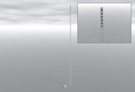
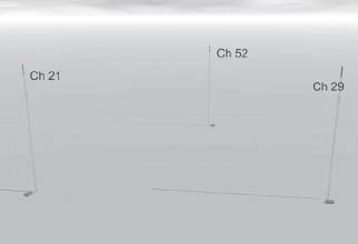
6.2
Terrestrial transmissions are often based on 300 m (1,000 feet) towers. At the top there is a red and white cover inside which you will find the UHF transmission antennas. Underneath are the VHF band III antennas and then the FM radio transmission antennas. The antennas are arranged according to frequency with antennas for highest frequencies on top and the lower the frequency the lower antenna position in the tower.
The TV broadcast transmissions that started in Europe in the 1950s used the VHF (Very High Frequency) bands between 47 and 230 MHz. These frequency bands are still used for the first national channel in most European countries except in the United Kingdom where VHF was left when the old 405 line system was shut down. Unfortunately the VHF band does not contain that many channels. In the lower part of the frequency range, band I, covering 47–64 MHz, there is only enough space for three channels: 2, 3 and 4.
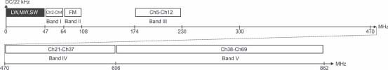
Figure 6.3 shows the frequency ranges for terrestrial TV. Band II 87– 108 MHz is used for FM radio while band III, 164–230 MHz includes channels 5, 6, 7, 8, 9, 11 and 12. During the 1960s, most countries in Europe wanted to start a second channel. Since the national TV stations had a monopoly in almost all European countries, the development of private TV was restricted and the number of channels was small. It took some time before the UHF frequency bands were brought into operation. In the UHF frequency bands, 470–862 MHz, there are much more bandwidth including channels 21–68.
However, distributing TV at these higher frequencies is much more dependant on a free line of sight between the transmitter and the receiver than is the case in the VHF frequency ranges.
FIGURE
6.3
Frequency ranges used for terrestrial TV.
As a total, there are quite a lot of channels in the terrestrial frequency ranges for TV. But there is also a serious problem. Every analog program channel will require a large number of used transmission channels to cover an entire country. The reason for this is that neighboring transmitters always must transmit at different frequencies (see Figure 6.4). They will interfere with each other even if they transmit the same program content and even if they are synchronized with each other. Since the terrestrial signals may travel quite far during good weather conditions, the necessary distance between two transmitters using the same channel must be quite large.
FIGURE
6.4
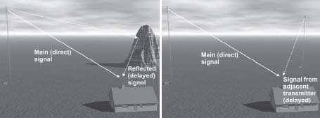
Adjacent transmitters need to use different transmission channels even though they transmit the same program channel.
For that reason, it is hard to get more than about five analog program channels with national coverage. The conclusion is that right from the start there were large limitations in how many channels could be provided using analog terrestrial transmitters. For many years, the viewers were pretty satisfied with two, three or four channels to choose from.
But during the 1980s, satellite and cable TV offered new possibilities. The analog cable TV networks can handle a much larger number of channels since every channel may be used in one single network. There is also more bandwidth due to the usage of S channels that are not allowed outside the coaxial cables.
ANTENNAS FOR TERRESTRIAL TV RECEPTION
There are three different kinds of antennas for terrestrial radio and TV signals. There are antennas belonging in each of the frequency ranges, band I (channels 2–4), band II (FM radio 87–108 MHz), band III (channels 5–12) and UHF bands IV and V (channels 21–69). Most antennas are based on the classical Yagi design that is well known to everyone (see Figure 6.5).
Yagi antennas are normally designed around a dipole that is half a wavelength wide. A dipole may work as an antenna on its own but will get equally sensitive in both directions. Since directivity in one direction is desired, the lobe in the backward direction may be suppressed with a reflector. The reflector also increases the gain in the forward direction towards the transmitter.
FIGURE
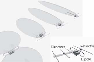
6.5
The Yagi antenna is the most common antenna for receiving terrestrial TV signals.
The reflector is a bit wider than the dipole. In terrestrial analog TV, directivity is desired to avoid reflexes. To achieve this, one or more antenna elements can be placed in front of the dipole. These elements are called directors and are less than half a wavelength wide. The larger number of directors the better directivity of the antenna.
In analog terrestrial TV, the reflexes are the largest enemies. Reflexes cause ugly “ghost” images and they are very hard to get rid of. The only way to avoid reflexes is either to live in a place with a clear line of site (no large buildings or mountains in the way) or to use an antenna with a large directivity.
Using an antenna with a large directivity to avoid reflexes follows the same principle that makes satellite TV free of reflexes. In the case of satellite TV, the transmissions are at very high frequencies and the antennas are quite large in relation to wavelength. Therefore parabolic dishes have a much larger directivity than is the case for terrestrial Yagi antennas in the VHF or even in the UHF frequency bands. Even if you use the largest UHF antenna, there is a high likelihood of reflexes in the picture.
Since the dimensions of Yagi antennas are related to the wavelength, there are practical limitations when it comes to the numbers of directors that can be added to obtain greater directivity and gain in the lower frequency bands. For the UHF band it is possible to construct antennas with a lot of directors. Therefore the directivity of UHF antennas is superior to the antennas in the lower frequency ranges.
The In-House Amplifier
In most European countries, the original national channel is transmitted in the VHF bands and the UHF bands are used for the additional channels. Therefore, there is a need to filter together one VHF and one UHF antenna in order to use just one cable to carry the signal from the antennas to the TV set(s). It is necessary to use a filter. If the signals are not filtered, one signal may enter the antenna system two different ways, causing ghost images similar to reflexes on the TV screen. In addition, half of the received power will be lost.
With a filter, it is possible to combine the antennas without compromise. The most common filters have one VHF input (band I or band III) and one UHF input. Sometimes there is an additional input for FM radio (band II). In this case, you must use an outlet that splits the TV and radio signals before they are connected to the TV set and the FM radio.
In many places, the received signal is very weak and it may be necessary to amplify the signal before it is distributed to the TV sets. In most homes, there are several TV sets and the signal is split up before it reaches the sets. Many people choose to use a filtering amplifier instead of a passive filter. The filtering amplifier is a combined filter and amplifier. These amplifiers often have two outputs, making it easy to connect to multiple TVs without suffering any losses (see Figure 6.6).
FIGURE
6.6
Many in-house filtering amplifiers have two outputs, making it easy to connect two TV sets with no losses.
When it comes to amplifiers, it is important to remember that the amplifier only compensates for the cable attenuation and splitting losses you have in the receiving system. It does not resolve problems related to receiving lowquality signals in the first place, so it is still important to have good antennas. Certain amplifiers may give an additional improvement of the reception, since their noise figure may be lower than the input noise figure of a conventional TV set.
No power outlet is needed in the attic or close to the roof since the amplifier can be remotely fed from a power supply placed close to one of the TV sets. The power supply uses the coaxial cable to feed the amplifier in the attic. Figure 6.7 shows an in-house filter amplifier and its power supply.
FIGURE
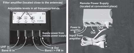
6.7
The in-house filter amplifier is often remotely powered using the coaxial cable to feed power from a power supply located next to the TV set.
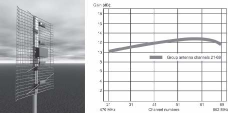
Another kind of antenna that is useful is the group antenna, which has four open dipoles and a reflector behind, shown in Figure 6.8. This antenna has a comparatively high gain combined with a large beamwidth and a very large bandwidth. If you are not subject to reflexes and the signals are not extremely weak, an antenna like this might be a good choice. It is also easy to put in an attic where you probably do not have that much space.
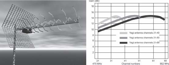
A Yagi antenna will not provide full gain across the complete UHF frequency band. This problem is illustrated in Figure 6.9. If you want to have an antenna capable of handling a wide frequency range, a group antenna combined with an in-house amplifier might be a good choice.
In most European countries, only one UHF antenna is needed to receive all channels. However in border areas around Europe, viewers often want to receive the TV channels from the neighboring country. Then UHF receptions from several directions may be needed.
FIGURE
6.8
Typical gain curve showing the bandwidth of a group antenna including four open dipoles.
FIGURE
6.9
Some typical Yagi antenna gain curves.
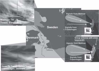
To get this to work when receiving analog signals, you have to use separate antennas for different directions. If you are extremely lucky, you might be in a position where the foreign transmissions are in line or almost in line with the domestic ones, as in Figure 6.10. However this is more likely the exception than the rule.
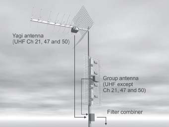
In all other cases, you must use a combining filter to avoid ghost images when receiving analog signals. This means tailor-made filters for UHF combination for every region. Figure 6.11 shows such a filter. In this case, the filter is designed to let the Yagi antenna (used to receive channels 21, 47 and 50) combine with the remaining parts of the UHF bands that are received by a broadband group antenna below the Yagi.
FIGURE
6.10
If you are lucky, the foreign signal comes from a transmission site that is in line with the domestic one. By using an antenna with a broader beam, you may be able to pick up transmissions without a combining filter.
FIGURE
6.11
A Yagi antenna is used for three channels coming in from the left. The rest of the UHF band is available from the group antenna below receiving signals from the other direction.
It is crucial to know which filter is used in the reception system. When you convert to digital reception, a large number of channels are added. Then you will have to know which input of the filter is the broadband input.
DIGITAL TERRESTRIAL TV
Analog TV suffers from two larger problems. One is the lack of bandwidth and the uneconomical ways of using the channels. This means that the number of channels is considerably less than for satellite and cable TV. The second problem is that the picture quality is very dependant upon local reception conditions. Digital terrestrial television, based on the DVB standard, has a very clever way to deal with both these problems.
To begin with, the same basic DVB transport stream is used as for satellite and cable TV. However, the transport stream is distributed using a much more complicated way of modulating the signal. As mentioned earlier, terrestrial signals are exposed to reflexes because hills, mountains and tall buildings interfere with the signal. Reflexes vary due to weather conditions and can also be caused by moving objects such as airplanes. Satellite dishes have narrow beams so the signals are much more stable because there are no reflexes. The secret of digital terrestrial TV is hidden in the way to modulate these signals.
In Europe the DVB-T standard based on, Coded Orthogonal Frequency Division Multiplex (COFDM) is used. This is completely different from the American Advanced Television Systems Committee (ATSC)-standard, which is described in Appendix A.
Coded Orthogonal Frequency Division Multiplex
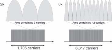
The COFDM systems have one similarity to the satellite and cable TV DVB signals: It uses amplitude and phase modulation. The standard allows for several ways of modulation. The most common is using 64 QAM just as for cable. What is special, though, is that it is not a matter of one carrier but thousands of carriers, each carrying a small portion of all information to be transmitted. There are advantages in spreading the information like this. If we use 64 QAM, each carrier may at a certain instant represent a symbol containing six bits. There are two versions of COFDM, 2k (2,000 carriers) and 8k (8,000 carriers). In the 8k system, there are really only 6,817 carriers that contain information to be used for our TV channels. The rest of the carriers have different functions, such as pilot carriers that are used by the receiver to examine the transmission channel. A simple calculation shows that 6,817 x 6 = 40,902 bits may be transmitted (symbolized) simultaneously. This is called a COFDM symbol.
If instead the 2k system is used, 1,705 carriers are used to carry actual data, representing 1,705 x 6 = 10230 bits that can be symbolized simultaneously (see Figure 6.12). Each carrier in a 2k signal will have to be four times wider than a carrier in the 8k system to match the amount of data carried in an 8k system. In this example, consider the same modulation scheme, 64 QAM, to be used in both the 2k as well as in the 8k signal. Each carrier can symbolize six bits every instant. What makes the 2k carrier wider is the fact that it has to change symbol four times faster than a carrier in the 8k system. The important thing is that in the 8k system, the receiver has four times more time to identify the symbol than in the 2k case.
FIGURE
6.12
COFDM using 1,705 and 6,817 carriers.
By using a very large number of carriers you may transmit many bits of digital TV simultaneously giving the opportunity to let each set of bits be on the air for a quite long time.
The receiver will always receive a signal that gets directly from the transmitter. If there is also a reflected signal, this signal will arrive at the receiver a bit later. If the symbol can be transmitted for quite some time, there is a chance that the reflected signal will contain the same symbol as the direct signal. This is the basic idea of creating a system that is not sensitive to reflections—letting everything happen so slowly that the direct signal and the reflections have the same content. Since everything happens four times slower in the 8k system than in the 2k, the 8k system can handle reflections that are four times longer than in the 2k system.
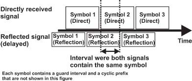
In both systems, each symbol (set of bits) is transmitted for a bit longer than is really necessary to keep the bitrate at the desired speed (see Figure 6.13). This extra time is called the guard interval, and it provides extra time for the receiver to identify the symbol while the same symbol is available in the directly received signal as well as in the reflected signal. The symbol is also surrounded by a cyclic prefix that helps the receiver synchronize several signals that are delayed in relation to each other.
FIGURE
6.13
Two signals are entering the receiver. There is quite a long interval where both signals contain the same symbols. The main task for the demodulator is to detect this interval and to decide the value of the transmitted symbol during this interval.
In Figure 6.13, the direct signal and the reflected signal are shown as they enter the demodulator of the receiver. The secret of COFDM is to detect the symbol while the same symbol is still contained in both signals.
Some of the transmitted carriers are pilots containing known information. These pilots are used by the receiver to calculate the actual reflection properties of the channel. This provides additional information that is used to select the correct time for identifying which value (which set of bits) is being transmitted.
Single Frequency Networks (SFN)
We have already seen that in the analog world, two adjacent transmitters distributing the same program channel have to use different transmission channels operating at different frequencies. This consumes an enormous amount of bandwidth. Digital systems do not work that way, fortunately. Using the capability of the COFDM receiver to receive signals that are delayed in relation to each other, it should be possible to receive signals from two transmitters simultaneously. However, in order to get this to work, the receiver has to experience the second signals as if it was a reflection of the first signal. If we let both transmitters distribute exactly the same signal and see to that they are absolutely synchronized, this condition can be fulfilled. Then the receiver can not distinguish a difference between a reflection and the “interfering” signal from the adjacent transmitter.
The possibility to use the same frequency in a larger area (including several transmitting sites) saves a lot of frequencies. An interesting comparison is that in satellite TV, as well as in cable TV, only one frequency is used for each service. By using SFN techniques, a similar situation applies for a digital terrestrial network as well.
FIGURE
6.14
The basic principle for single frequency networks (SFN) is making the receivers believe that the interfering signals are really ordinary reflections by giving them the same technical properties.
Choosing 2k or 8k
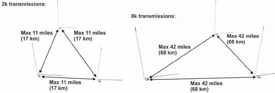
The choice between 2k and 8k is due to the distance between the transmitting sites. We have already seen that everything is four times slower in 8k than in 2k, making the 8k system capable to handle reflections that are four times longer than in the 2k system. If we regard an interfering signal as a reflection, the allowed distance between two interfering stations must be four times larger for an 8k system than a 2k system (see Figure 6.15). In some countries, such as the Untied Kingdom and Germany, the distance between stations is short. Therefore, the 2k system has been selected. In other countries, such as Spain and the scarcely populated Scandinavian countries, the 8k system is used because the distances between the existing transmitting stations are longer.
Using the 2k system, the distance between the transmission sites can be up to 17 km (11 miles) in order to get SFN to work. However, with the 8k system, the distance between the SFN transmission sites increases to a maximum of 68 km (42 miles).
From a receiver point of view, the selection between the 2k and 8k systems does not matter any more since most receivers nowadays are equipped to receive both systems.
FIGURE
6.15
Since the symbol rate is less when using the 8k system, the time interval where both the direct signal and the reflected signal contain the same symbol will be longer. For this reason the distance in between two adjacent stations may be longer than is the case when using the 2k system.
The Pre-Echo Problem
The basic premise of COFDM is to handle reflections. SFN is a later invention based on the resistance to reflections that is built into the system. In order to choose the right instant to identify the symbol, many COFDM reception chips assume that the first signal to arrive at the receiver is the strongest. When handling reflected signals this is always true. However in an SFN, that is not always the case. If transmitters always have equal transmission power, this would probably be a very minor problem, but frequency coordination issues complicate matters a bit. In Figure 6.16, you can see such a case in Sweden. The Malmö transmitters are coordinated at a power level that is one-fourth of the power transmitted from Hörby TV transmission station. The Malmö and Hörby transmitters are in the same SFN network to preserve frequencies. This is important in this area, due to a tough coordination situation at the border area to Denmark.
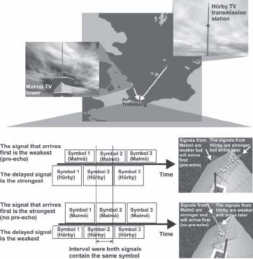
FIGURE
6.16
Always see to that you get the strongest signal first when receiving signals from a COFDM Single Frequency Network. Otherwise the receiver might not work due to the pre-echo phenomenon.
In the small town at the bottom of the map, Trelleborg, people have used the signals from Hörby instead from Malmö for decades since the Hörby analog signals contain all channels in the UHF band and you will only have to use one antenna for all channels. When introducing digital TV this is not a good choice of reception.
The problem is that the signals from Malmö will come in first but will be weaker since the antennas are turned towards Hörby. The Hörby signals will be stronger both due to the fact that the antennas are turned there and that the transmitters are stronger. There will be a pre-echo effect, making it hard for the receiver to keep track of which symbol to compare to which when trying to get the right instant for symbol identification.
A way to solve this problem is to turn the antenna towards Malmö instead. Now the Malmö signal will be stronger since the antenna is pointing in that direction. The Hörby signals will continue to interfere but will be weaker than the signal that is first to enter the receiver and the pre-echo effect is cancelled.
MULTI-DIRECTIONAL ANTENNA SYSTEMS
Digital TV using the COFDM technique is almost completely insensitive to reflections. And the reflections will never cause any visible problems in the picture. In analog terrestrial television, reflections were the most disturbing problem and therefore antennas with a high degree of directivity have been prioritized. Since we don't have to put priority on directivity for antennas used for digital TV, we might use omni-directional antennas. This may solve problems where we wish to both receive signals from several directions and signals that are spread over the entire UHF bands. Omni-directional antennas for TV have existed for many years but the use has been limited to caravans and boats where ease of operation has been more important than picture quality.
From a theoretical point of view, it is also possible to combine two antennas using a broadband combiner without filtering. However if you do that, it is essential to see to that it will not cause any pre-echo effects. In Figure 6.17, a scenario for combining two antennas without using any filters is shown. Half of the received power is lost, but the pre-echo problems are avoided by carefully selecting the location of each antenna and keeping track of cable lengths. The important thing is to be aware of is that both antennas will receive both signals and you will have to ensure that the strongest signal always arrive at the receiver before the weaker signal from the other antenna.
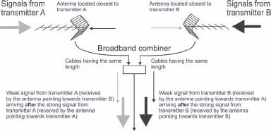
FIGURE
6.17
When combining two antennas without filtering for multi-directional COFDM digital TV reception, the strongest signal should always arrive before the weaker, undesired signal.
INDOOR ANTENNAS
Indoor antennas can be used if you live very close to a transmitter. If you have a weak signal, like most people, you must still use an outdoor antenna. But if the signal strength is enough, an indoor antenna will provide full picture quality much easier than was the case for analog transmissions.
For these reason, lots of new active (antennas that contain an amplifier) indoor antennas have been designed for indoor digital TV reception. The antenna may be connected directly to the receiver, like the early model from Nokia in Figure 6.18. This antenna is fed by 5-volt power supply at the antenna input of the receiver.
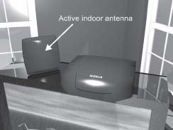
FIGURE
6.18
Nokia 212T connected to an early active broadband antenna from that same company.
Omni-Directional Antennas
Figure 6.19 shows another solution that is suitable for digital TV. This is an outdoor broadband active and omni-directional antenna. This is a way to receive signals from different directions across the complete UHF band. Since it can be located outside, it will work even at low signal levels. It is much better to use an outdoor antenna, since walls and roofs tend to significantly attenuate the UHF signals, especially the higher channel numbers that are at 800 MHz or more.
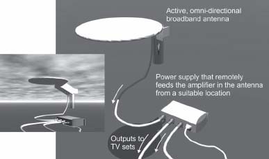
FIGURE
6.19
Active, broadband and omni-directional antenna from Danish manufacturer Triax is suitable for digital reception.
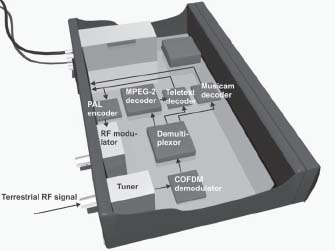
DIGITAL TERRESTRIAL RECEIVERS
The digital terrestrial receiver is different from the corresponding satellite and cable receivers when it comes to the input stage, the tuner and the demodulator. The tuner covers the UHF bands and, in some cases, the VHF bands as well. In some European countries, the VHF bands have been abandoned and only UHF will be used for further distribution. However as the analog transmissions cease, it might be possible that even the VHF bands will become popular again for digital distribution, because mobile reception is much easier at lower frequencies. Another situation where VHF is preferable is for MATV systems where the coaxial cable network is not suitable for UHF distribution. Then incoming UHF channels may be converted to VHF before being sent into the coaxial network.
After the tuner, we have a COFDM demodulator and after this the 22 Mbit/s transport stream is regenerated (see Figure 6.20). This transport stream usually contains about five standard definition TV channels. The rest of the receiver is quite identical to satellite and cable TV DVB receivers.
Note
22 Mbit/s is an approximate figure. By using different modulation parameters, the bitrate in a transmission channel may vary. However the 22 Mbit/s choice is a good compromise between capacity and channel robustness.
To compete with satellite and cable, it is essential to get as many channels as is possible into the terrestrial networks. Statistical multiplexing is often used to increases the number of MPEG-2 TV channels from four to five in one terrestrial multiplex.
FIGURE
6.20
In a European terrestrial digital receiver, the tuner in most cases operates within the UHF band, 470–860 MHz. The tuner is followed by a COFDM demodulator.
DVB-T RECEIVERS
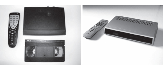
The introduction of terrestrial digital TV is complicated because in the long run this means closing down the analog transmitters. This will force all viewers to buy digital receivers either as separate boxes or integrated receivers in the TV sets.
To make the transition to digital TV easier, a wide variety of small STBs (set-top boxes) have been developed. These small units can be placed on top of the TV set, hence the name. Earlier designs have had to be placed on a shelf underneath the TV set. The new devices are not much larger than an ordinary VHS video cassette.
FIGURE
6.21
Small size STBs from Swedish manufacturers Emitor and Tevebox.
TERRESTRIAL TV FOR MOBILE DEVICES; DVB-H
The latest addition to the DVB family of standards is DVB-H. “H” stands for Handheld. This standard is optimized for distribution of TV signals to handheld devices such as cell phones or other mobile devices.
The DVB-H standard is based on adding special signals to an ordinary DVB-T multiplex. These signals are special in several ways. First, the DVB-H signal is based on IP Internet Protocol Packets and thus similar to IPTV (covered in Chapter 6). Another difference is the signal is split into signal bursts instead of being a continuous signal. The idea of sending small bursts of information is that the receiver part or the mobile phone can be switched off between the bursts to preserve battery power. Since the receiver quickly learns the rate and length of the bursts, it knows when to switch on and off.
Another thing that is different from stationary DVB-T reception is that the mobile device only can have a small antenna. This is compensated by even more powerful error protection (adding extra bits for restoring destroyed packets) than is the case for the DVB-T signal.
DVB-H is distributed at considerably lower bitrates than DVB-T for stationary reception. In a cell phone, there is no need for HDTV, since the mobile units use very small displays. Therefore bitrates in the range of 300 kbit/s might be considered for each TV channel. This is to be compared to 3 to 4 Mbit/s per channel for an ordinary standard definition TV channel or up to 16 Mbit/s or more for an HDTV channel.
An interesting aspect of mobile television in cell phones is that there is a return channel, which is not always the case for stationary TV. This means that the broadcaster, the transmission service operator, the mobile phone operator and Internet service providers can work together in completely new ways.
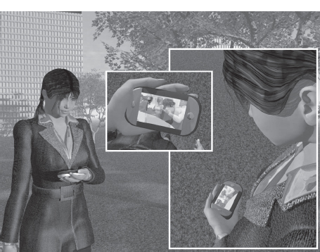
FIGURE
6.22
DVB-H is the latest addition to the DVB family of technical standards for distribution of TV.