9 |
Connecting the Devices |
| CHAPTER |
FIGURE
9.1
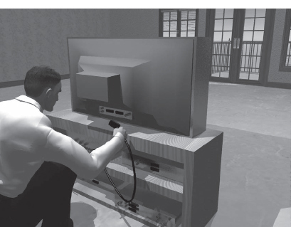
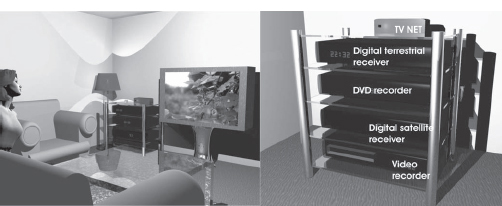
There is a lot to say about connecting devices to the TV set.
After a while, all TV viewers will discover their personal preferences for connecting the electronic devices in their homes. This may require several different communications networks in the home.
The oldest communication network in the home is the telephone connection. Another network that has been around for a very long time is the cabling from the TV antenna to the TV sets. Nowadays, there is a third network in most homes, the IP network which serves the computers with Internet connection as well at tying the computers to each other.
In this chapter, we will take a deeper look at how these three kinds of networks can be designed and improved. As the digital signals are introduced, it may be a good idea to check everything and see what can be done.
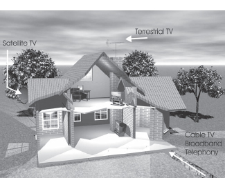
Lots of viewers have combined their terrestrial TV system with satellite reception. The satellite signals are fed from a satellite dish to a receiver installed on the most-used TV set in the home. If the viewer instead is connected to cable, he might do with just one means of reception. The cable TV network contains all important channels and there might not be a need for additional signals.
However, it is not just a matter of bringing the signals into the house. Modern homes are stuffed with electronic devices that require signals from satellites, cable, terrestrial transmitters and the Internet. The next step is distributing these signals around the home.
FIGURE
9.2
In most modern homes, there are radio and TV signals either from terrestrial transmitters, satellite, cable or broadband.
THE ANTENNA SYSTEM FOR TERRESTRIAL SIGNALS
The traditional antenna system for TV in a home is based on antennas that are located on the roof, in many cases on a tube attached to the chimney. The antennas are combined to one coaxial cable which uses either a passive filter or an in-house amplifier, performing the filtering and amplifying the signals to suitable levels for further distribution within the building (described in Chapter 6, “Digital TV by Terrestrial Transmitters”).
Coaxial Cabling
In many cases, there is a cable from the antenna system to the living room. Coaxial cables are often housed in the same kind of plastic tubes used for the electrical cabling. Even in older houses, there might be plastic tubes in the walls where this cable is located. If you are lucky there are tubes even to other rooms in the house. When constructing a new house it is essential to see to that there are tubes from the attic to all rooms from the start. Even if there is no need for cables to all room in the beginning, such needs will occur sooner or later. Otherwise cabling to different rooms later might be very difficult and time-consuming.
In-house amplifiers usually only have one or two outputs. The supply voltage to the amplifier is usually done using the coaxial cable. This allows the power supply to be at a convenient place, such as the living room, and no electrical outlets are required in the attic. Then the outputs of the amplifier system are on the power supply. But there is a problem with this. It might not be wise to have cables go from the living room to the other rooms; it would be better if the cables went straight from the attic to the different TV sets in the house. This means putting the power supply in the attic. Then it is easier to split the signals to the different antenna outlets of the house. After the outputs of the power supply we do not have to care about supply voltages in the cables.
FIGURE
9.3
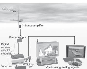
The in-house amplifier is the heart of the distribution system for terrestrial signals. It is also an easy and classic way to spread RF modulated signals from digital receivers and video and DVD recorders, with built in RF modulators, around the house.
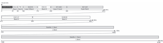
The terrestrial signals are at frequencies below 862 MHz and are distributed using coaxial cables that, in reality, can handle even higher frequency ranges. Therefore, the same cables can be used to distribute the satellite signals from the satellite dish to the satellite receiver. These signals are in the range 950–2150 MHz. But the higher frequency, the higher is the attenuation in the cables.
FIGURE
9.4
Splitters
Splitters can be attached at the output of the power supply of the in-house amplifier. There are different numbers of outputs from the splitters but most common are two- or four-way splitters. But the loss in the splitter will increase with the numbers of outputs. The splitter is a small box which contains a printed circuit board where the coaxial cables are connected using screw attachment. We can't just attach the cables to each other in a pure galvanic way without the printed circuit in the splitter because the input and the outputs have to be matched to each other. The signals are electromagnetic waves and all connections have to be matched to avoid the waves from getting reflected. As a comparison, we can look at a wave in the ocean as it approaches the beach. The sandy beach is a thicker media than water and therefore the wave is reflected back into the ocean. The same thing applies to a radio wave which is entering a change in the media as when traveling through a cable and coming to a split point. If we just split up a signal without first making arrangements so that the wave does not feel the media change, we get reflections. In analog TV signals, we will see these reflections as ghost images. The splitter matches all the signals so no reflections are created.
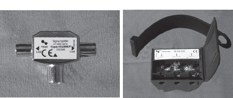
Another reason for using splitters is that the outputs should be isolated from each other. TV sets and receivers contain oscillators creating internal radio signals that are used for frequency conversion of the incoming signals. These local oscillator signals may cause problems if their signals leak out in the wrong directions. Spurious signals that may be radiated from the antenna input of one TV set can affect the received signals in another TV set that is connected to the splitter, unless properly isolated. Small, cheap splitters do not provide any isolation between the outputs while more advanced (and costly) splitters contain directional couplers that sometimes may be needed quite badly to get sufficient isolation between the connected sets. Figure 9.5 shows examples of each.
FIGURE
9.5
The simple splitter (left) provides matched input and output but no isolation between the ports. The splitter to the right provides matched connections and also offers isolation between the inputs.
It may also be good to know that it is possible to use a splitter in the reverse direction, as a combiner of two and more signals. We will return to this subject later on.
Outlets and In-House Networks
The signal that is obtained from the output of the power supply of the amplifier may be connected straight to the antenna input of a TV set. However, in most cases, a wall outlet is put in each room partly for aesthetic reasons, but there are also technical reasons. In the outlet, a filter separates the FM radio (band II) from the TV bands so one cable connects to the radio and the other to the TV set. In addition, it might also be practical to be able to use a shorter cable inside the room. This might be practical if you move the TV set. Then it is just a matter of choosing the right length of cable between the outlet and the set.
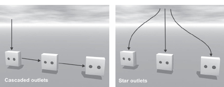
It is preferable to design an in-house network as a star-shaped network (see Figure 9.6). Remember that you should use outlets designed for star networks, which only have one connection to the antenna system. The other kind of outlets, for cascaded networks, also has an output connection to continue the cable to the next outlet. Really, cascaded outlets are splitters dropping off a small portion of the signal in the outlet and feeding most of the signal on to the next outlet. The relationship between the signal dropped off and the signal that is fed on to the next outlet varies. The first outlet in a branch might have just one-tenth of the signal while the outlet before the end outlet has half of the remaining signal power. The last outlet must be the star outlet kind since we want to terminate the signal.
FIGURE
9.6
Cascaded and star-shaped networks require different kinds of outlets.
Mounting IEC Connectors
A coaxial cable consists of an inner conductor, dielectric insulation material and an outer coaxial conductor, which is the reason for the name. On top of that there is an outer insulation protecting the cable. The outer conductor is usually connected to ground and acts as a shielding against signals from the outside.
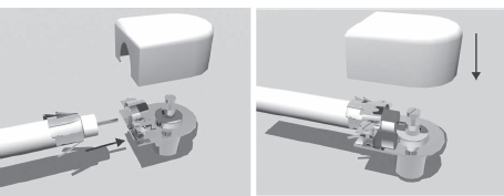
When an IEC is to be mounted on a coaxial cable, about 1 centimeter (0.4 inch) of the outer insulation is removed. Then the outer shielding is pulled back over the outer insulation. Finally, five to seven millimeters (0.2 to 0.3 inches) of the inner insulation is removed. In Figure 9.7, you can see what it all looks like after this. In the IEC connector, there are two screw attachments for the inner and outer conductor respectively.
FIGURE
9.7
Mounting an IEC connector to a coaxial cable.
Note
When working with the cabling from an in-house amplifier be sure to unplug the power supply before you start. A short circuit on the input or outputs of the amplifier system may destroy the amplifier immediately.
Another important thing is to avoid bending the coaxial cables. You have to allow a certain minimum radius of the cable when passing corners. If the cable is bent too much, there will be a mismatch and a reflection in the bend. Of course you should not press cables in closed windows since this will also cause reflections and, in the long run, completely destroy the cable.
The antenna cable to the TV antenna input requires a female connecter in the TV set end.
Some more modern in-house amplifiers don't use screw attachments but F connectors instead. This is the same kind of connectors that are also used for the cabling between LNBs, DiSEqC switches and satellite receivers.
CONNECTING THE DIGITAL RECEIVER TO THE TV AND OTHER VIDEO DEVICES
When the first commercial video recorders for consumer use showed up at the end of the 1970s, it was necessary to connect the video tape recorder through the antenna input of the TV set. In those days, most TV sets had no audio and video inputs at all. For this reason, the built-in RF modulator, essentially a miniature TV transmitter, became popular in all video devices. The modulator converts the audio and video signals into a common analog TV channel that can be received by any TV set. In the beginning, all such European modulators were delivered tuned to channel 36 in the UHF band. In order to get the whole thing to work, the video recorder also needed an antenna input of its own.
At the output of the video device, the internally generated TV channel is added to the incoming signals from the aerial.
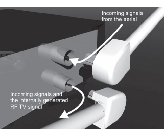
FIGURE
9.8
In devices with a built-in RF modulator, the incoming signals are combined with the internally generated TV channel that contains the signals from the video device.
As time passed, more and more devices, such as TV games, started using internal RF modulators. The analog satellite receivers got the same feature when they were introduced during the 1980s. Nowadays, all TV and video devices in Europe have scart connectors (more on scart in the next section). This is also the most common way to connect the TV to digital receivers and so on. But the built-in RF modulator still exists in most devices, primarily because it's easy to bring the signals on to other TV sets around the house.
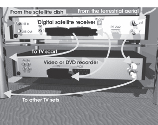
Figure 9.3 showed how a digital receiver and a video recorder (or a DVD recorder) could be cascaded before the combined signals from both devices are distributed to the TV sets. In Figure 9.9, the modulated signals from a digital satellite receiver are sent back up to the attic to be combined with the other signals at the in-house amplifier.
The digital receivers are usually designed to let the signals from the attached video device (DVD recorder) use the built-in modulator if the external source is turned on. In this way, you can use the modulator of the digital receiver to distribute the signals from the video device to the other TV sets in the house. However, it is essential to connect the devices exactly as is shown in Figure 9.9 to avoid sending a modulated signal goes the whole way around the system and back to the device where it was created. Then the complete system begins to oscillate and this won't work. At the in-house amplifiers, the signals from the antenna and the modulated RF signal from the satellite receiver are connected using a reversed splitter as a combiner.
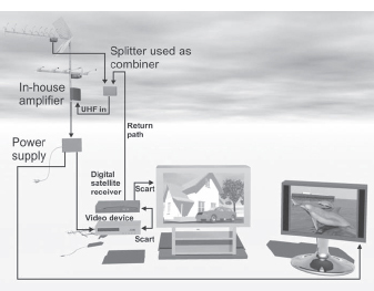
FIGURE
9.9
The RF signals generated by the satellite receiver (the satellite dish is not shown in the picture) are sent to the attic and the in-house amplifier to make them available in other TV sets in the house.
USING SCART CABLES
SCART is French and stands for Syndicat des Constructeurs d'Appareils Radiorécepteurs et Téléviseurs. The connector is also called a Peritel connector or Euroconnector, but most people in Europe today just call it “scart.” It was accepted as the standard for cabling in the 1980s. Before we dig deeper into the scart connector we will take a closer look at the alternative way of connecting the devices; using the built-in RF modulator.
RF modulators still exist because they are an easy way to distribute signals around within buildings. The point is that the existing coaxial cables that still have to be used or the signals from the aerial system can be reused. However if the coaxial cabling carrying modulated signals is used between the digital receivers and the TV sets, the audio and video quality will be lower than if using a scart connection.
Another limitation is that the built-in modulators do not allow for stereo audio distribution. There is only one low-cost consumer product in Europe that allows for RF modulated NICAM stereo distribution (and by low cost, I mean in the range of 350 euro). That is the three-channel digital Multibox receiver by Swedish manufacturer A2B. This receiver takes three digital terrestrial free-to-air channels simultaneously and modulates them to conventional analog channels. This product solves the problem of terrestrial analog closedown that has started in some European countries such as Germany and Sweden. The smart thing about the Multibox is that the viewer can still use all TV sets and video devices along with the remotes without thinking about that the analog terrestrial network has been shut down.
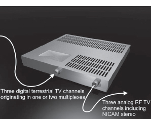
FIGURE
9.10
The Multibox provides three modulated analog TV channels, including NICAM stereo from three digital terrestrial channels.
With the exception of the Multibox, the only way to get stereo audio is with scart cables or separate audio and video cables. Outside Europe, cables with RCA connectors are commonly used to interconnect TV sets and video devices. Digital receivers made in the United States or in Asia frequently use these connectors. In Europe, RCA connectors are used primarily to connect external audio systems such as stereo- or home cinema amplifiers. There are also digital ways to connect the audio from the digital receiver or DVD recorder, which we will return to in Chapter 11, “The Home Cinema.”
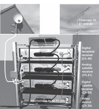
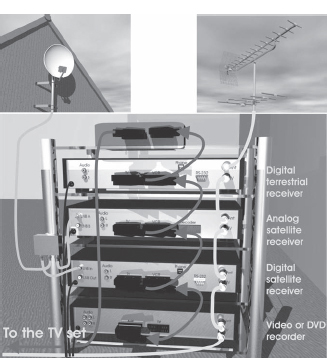
As shown in Figure 9.12, there might be a bunch of devices to be connected to the TV sets, including digital receivers, analog receivers, video recorders, DVD players and recorders, etc., so using the scart connections economically is important.
FIGURE
9.11
The RF modulated signals from several receivers and video devices can be combined by cascading the RF inputs and outputs. (See color plate.)
FIGURE
9.12
Quite easily you will get a whole rack of receivers and players.
The Scart Connector in Detail
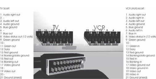
The scart connector has 21 pins. There is a reason for the large number of connections. The scart connector was introduced in the early 1980s to make way for the television of the future (the television of today). Two things were considered as important. First, it needed to be able to handle stereo audio connections. Secondly, it should be able to connect component-encoded signals, the R, G and B signals. And it was also quite natural that conventional composite video should be handled using the new connector. A video recorder can not handle RGB signals. The video recorder records a modified version of the composite PAL or SECAM signal. Finally, there are pins that may be used for different kinds of signaling between the devices.
There are two kinds of scart connections on the devices. Those marked “TV” are one-way connections to connect a TV set. The other kind is marked “VCR” (Video Cassette Recorder) and allow for two-way traffic, since a video recorder (or DVD recorder) must be able to receive as well as to deliver signals.
The oldest usage (around the end of the 1980s) for the scart cables was to connect stereo video recorders to the TV sets. A scart cable to connect to the video recorder uses the composite pins and the audio pins (see Figure 9.13). This kind of scart cables is a bit thinner than those where all pins are connected.
DVB signals are component-encoded and RGB connection should be used. For this reason a “full” scart with all 21 pins connected is the only option if you wish to enjoy full picture quality. The same thing applies when connecting a DVD player or recorder to your TV set. The signal stored on DVDs is also based on MPEG-2 compression and component-encoded signals. Strangely enough, there are still some cheap DVD players available without component video.
FIGURE
9.13
The pin configuration in the scart connectors on a set-top box.
Simple Scart Connector Configurations
The most common way to connect a video device and a digital receiver is shown in Figure 9.14. The video recorder or DVD recorder is connected using a scart cable to the VCR scart connection on the digital receiver. The digital receiver is then connected to the scart connector on the TV set. It is important that the cable between the digital receiver and the TV set is of the “full” scart type, with all 21 pins connected. When connecting a DVD recorder, the “full” scart is also important, since the DVD recorder may take full use of component video (unlike the VHS machine).
To play a recording from the VHS recorder or the DVD recorder, the signals travel through the digital receiver and then on to the scart cable that is connected to the TV set. In most cases, the digital receiver also sends the signals to the built-in RF modulator, as discussed earlier. The digital receiver handles all the traffic from the video device to the TV set. On the other hand, to record a program from the digital receiver, the recorder must be set to the AV input position (Audio Video). The signals are taken through the scart cable and the program will be recorded with stereo sound. Connecting the video recorder this way is the same as in the analog years, when the receiver was an analog satellite receiver.
To get the different devices to understand how to react when the user wants different connections to be established there are control signals in the scart. The pin configurations shown in Figure 9.13 are in the scart connectors of a set top box. When there is a video signal available, 12 volts is sent through pin 8 to the TV set from the TV scart to tell the TV set to change from RF to video input and start listening to the digital receiver. The VCR pin 8 input is used in the same manner to let the digital receiver detect a 12 volts from a video or DVD recorder and to route the video/DVD recorder audio and video output signals on to the TV set when needed. Pin 12 can be used for data exchange between recorders and TV sets. To use this you usually need devices of the same brand.
FIGURE
9.14
The most common way of connecting a video recording device to a digital receiver.
The cabling illustrated in Figure 9.14 is probably sufficient for most home situations. But in many cases, there are more devices to be connected to your TV set than there are scart connectors on the set. It is always better to choose a TV set with more scart connectors than you think you need.
Chaining Devices with Scart Connectors
If you only have one scart connector on the set, Figure 9.15 is what you may end up with—a scart “chain” where the devices are connected one after another.
The most important thing is to note that scart connectors on digital receivers marked “TV” can only deliver signals, not receive signals as connectors marked “VCR” can. This means your chain may place limitations on which devices you will be able to make recordings from. In Figure 9.15, for example, the video recorder is at the bottom. Except from recording analog TV using its own built-in receiver, it can only make recordings from the digital satellite receiver, which is located right above it. The two upper devices may be watched on the TV set but cannot make any recordings. Of course, all devices have to be either turned on or in stand-by mode for this chain to work.
If you find the simple or chaining methods insufficient or undesirable, external switch boxes provide an additional option. Switch boxes enable you to make recordings from any device. However, you also have the inconvenience of not being able to make the switch using your remote control(s).
FIGURE
9.15
Several devices may be connected one after another in a scart “chain.” But there are compromises to be made since it is a matter of one-way communication. (See color plate.)
Wireless Scart Connections
Another case for extra accessories is transferring audio and video to a TV set in another room and you want to have the audio in stereo. It might not be appropriate to use scart cables that are 10 to 20 meters in length since these cables are as thick as your pinkie and not very beautiful to look at. They do not exist in standard lengths that are more than 5 meters (about 16 feet). Wireless solutions like the devices discussed in Chapter 7, “Digital TV by Broadband” offer a good solution. In that case, it was connecting a computer to a TV set in another room, but the same solution can apply to connecting a digital receiver or DVD recorder to a TV that is at the other end of the house.
As shown in Figure 9.16, the wireless system serves as an invisible scart cable. Both units have a scart connector as an interface and are connected to the digital receiver and the TV set using short scart cables at each end. In many cases, wireless systems like these may be a very good solution to avoid actual cabling. However systems of this kind have a few drawbacks. First, the audio may become a bit noisy because of the analog FM modulated transfer of the signals. The same may happen with the video, because it is in composite PAL format and not component-encoded. Additionally, you may end up in problems if the 2.4 GHz signal has problems penetrating the walls in your house. Metal objects and people moving around may obstruct the signals.
It should be noted that the system's own transmitter is connected between the devices to which signals are distributed and the TV set, so the unit does not consume any of the scart connections itself.
FIGURE
9.16
The basic principle for a wireless scart extension system.
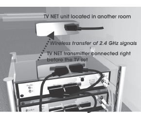
Figure 9.17 shows a very compact version of the wireless scart extension system. This is the Philips TV NET-300 and it also contains a return channel for the IR commands that are picked up from the remote control in the other room. It is also possible to use additional receivers to supply even more rooms with signals from the transmitter unit. Today, there are quite a lot of different brands of this kind of product.
The scart cables and connectors will probably be history in some years. HDTV receiver and the new flat-panel TV sets and other display systems require digital connection instead of the analog scart. In Chapter 12, we will take a closer look at the DVI (Digital Video Interface) or rather the HDMI (High Definition Multimedia Interface) that is about to replace the scart and other analog means of connecting the receivers with the display systems.
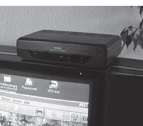
FIGURE
9.17
The Philips TV-NET wireless scart extension system also include a return path for the commands from the remote control that is used in the other room. In this picture the signal is transferred from a computer.
CONNECTING A SATELLITE DISH TO MULTIPLE RECEIVERS
Most people today have just one satellite receiver connected to their satellite dish. As were discussed in Chapter 4, “Digital TV by Satellite,” satellite reception is primarily based on the assumption that only one TV channel is received at a time. The satellite receiver sends DiSEqC commands to a single DiSEqC switch to choose the desired orbital position, and a 22 kHz control signal and an LNB supply voltage (14 or 18 volts) are sent to tell the LNB in what part of the frequency band and at which polarization to find the desired channel.
However, in a modern home there might be different opinions about which channel to watch (see Figure 9.18). There are lots of ways to distribute the signal from one single digital set-top box to different rooms in the house. You can even control the digital receiver from wherever you are using the remote and the return channel of a wireless scart extension system. But still you can not receive several channels simultaneously.
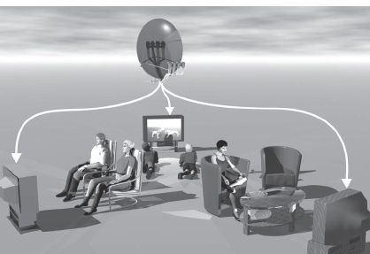
FIGURE
9.18
To split the signal from one satellite dish to several TV sets may be quite complicated if flexibility is important.
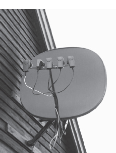
FIGURE
9.19
A conventional satellite dish only has one output from each LNB and one DiSEqC switch allowing only one channel to be received at a time.
Two satellite receivers may be connected to the same satellite dish if an external smart switch is used. The smart switch has one input for the satellite dish and two outputs, master and slave. If the receiver connected to the master output is in operation, it is in control of the antenna system, and if it is switched off, the receiver connected to the slave output may use and control the antenna system. The smart switch can be located anywhere (except near any of the receivers) so you can be “smart” about your cabling as well (see Figure 9.20).

FIGURE
9.20
The smart switch must not be located close to any of the receivers but could be placed at a suitable location to minimize the cabling that need to be done.
If any of the receivers have a “loop through” feature (discussed in Chapter 8, “Choosing the Right Box”), no external smart switch is needed. The smart switch is an integrated part of the receiver. You may still want an external smart switch to reduce your need for external cables.
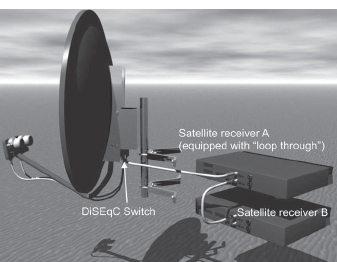
FIGURE
9.21
Receivers with a “loop through” feature do not need an external smart switch.
Fully Flexible Satellite Receiver Connections
In our modern time with universal LNBs, it's the DiSEqC signaling that controls the choice of received orbital slot, a 22 kHz tone that controls what part of the frequency band is to be received, and the choice of supply power to the LNB that controls the polarizations of the received signals.
To connect several satellite receivers that can work completely independent of each other, both parts of the satellite downlink frequency band, as well as both polarizations, have to be received simultaneously. More advances types of LNBs make this possible.
Quattro LNB
Reception at European cable TV headends has long demanded this type of connection. There, access to both parts of the downlink band as well as both polarizations is necessary to enable reception of any channel needed in the network. The Quattro LNB (also called just Quad) can handle this because it has four outputs, each dedicated to one part of the frequency band (10.70– 11.70 GHz or 11.70–12.75 GHz) and one sense of polarization (vertical or horizontal). Using a Quattro LNB, four or more channels, located anywhere in the downlink frequency band and in any polarization from a certain orbital position, can be received simultaneously.
Figure 9.22 shows a block diagram of a Quattro LNB. It has a low noise amplifier for each polarization. On top of this, both local oscillators, 9.75 and 10.60 GHz, are always in operation to get four mixers going. Finally, there are several i.f. amplifiers in operation.
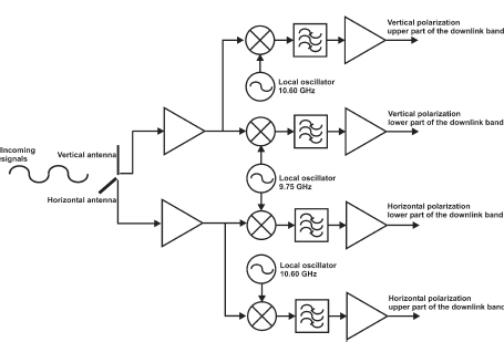
FIGURE
9.22
Block diagram showing the principles used in Quattro LNBs, suitable for satellite reception in cable TV headends.
In one way, the Quattro LNB is simpler than an ordinary single LNB. It does not have to handle the 22 kHz and dual voltage (14/18 volts) control signals from the satellite receivers. Instead it has its four outputs each delivering its part of the received signals from the satellite. A Quattro LNB is more or less four LNBs in the same casing.
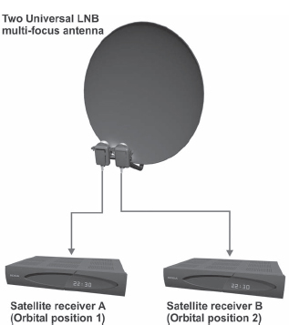
Twin Universal LNB
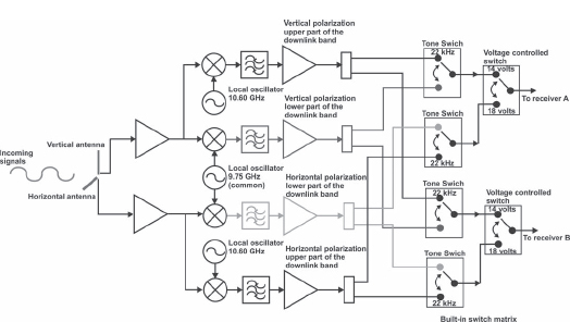
The Twin Universal LNB is an extension of the Quattro LNB, where dividers and switches have been added to accept two separate satellite receivers on each of the outputs. These receivers can then work completely independently from each other, as if each receiver has its own LNB.
In Figure 9.23, two LNB multi-focus antennas are shown. Each receiver has its own two-way DiSEqC switch. Each switch is connected to one of the outputs on each LNB. This configuration is the same as if each satellite receiver was connected to its two of its own LNB multi-focus satellite dishes. The setup can be used either to serve two satellite receivers in the same home or to serve two separate households with satellite TV.
Figure 9.24 shows a block diagram of the Twin Universal LNB. This LNB has to take care of the control signals from each receiver.
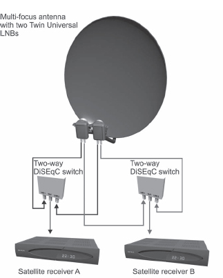
FIGURE
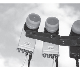
9.23
Multi-focus antenna with two Twin Universal LNBs. This antenna can provide signals to two satellite receivers that may operate independent of each other.
FIGURE
9.24
The principles for a Twin Universal LNB.
Quattro Universal LNB
The Quattro Universal LNB works very much the same as a Twin Universal LNB, but with an even more complicated switch matrix. It has four outputs that can control four separate satellite receivers (see Figure 9.25).
FIGURE
9.25
Quattro Universal LNBs have four outputs, like Quattro LNBs.
It is now possible to connect four independently operating LNBs to one single antenna (see Figure 9.26). You might say that there are a whole bunch of switches and dividers have been integrated in the LNB. (Yet another example of what you can do with micro electronics!) However, the DiSEqC switches, used to select the orbital position, must still stay outside the LNBs.
FIGURE
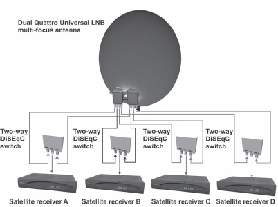
9.26
A dual Quattro LNB multi-focus antenna can supply four separate homes with satellite signals from two orbital positions.(See color plate.)
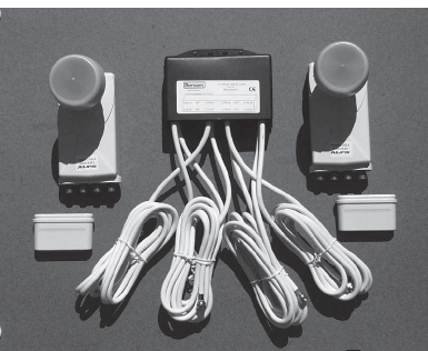
There are ready-made package solutions (see Figure 9.27) where four two-way DiSEqC switches are combined in a common case. The connection cables are delivered complete with F-type connectors mounted on the cables. This will give you a very compact and comparatively cheap solution for four households. One dish instead of four dishes is a big advantage. However, the households must be quite close to each other. A solution like this can also be useful in a single home where four different satellite receivers that are to be operated independently from each other.
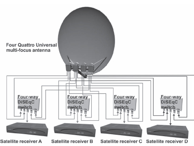
Using four Quattro Universal LNBs in a four-slot multi-focus antenna makes it possible for four receivers to reach four separate orbital positions independent of each other (see Figure 9.28). The Quattro Universal LNBs are followed by four four-way DiSEqC switches. One switch is needed for each receiver.
FIGURE
9.27
A complete set of equipment to build a dual Quattro LNB multi-focus antenna. All switches are contained in the same casing and the cables are ready-made, complete with F-type connectors.
FIGURE
9.28
A four Quattro LNB multi-focus antenna can supply four separate homes or receivers with satellite signals from four orbital positions completely independently. (See color plate.)
But isn't there a simple solution for anyone with one two-slot multi-focus antenna who do not want to buy more expensive Twin or Quattro Universal LNBs? Yes, there is. Figure 9.29 shows what can be done if you have, for example, two proprietary receivers with operators that use one of the orbital slots each. Remove the DiSEqC switch and let each receiver be used for just one satellite position.
The advantage in doing this is that you may use both satellite receivers simultaneously and independently from each other. The disadvantage is that each satellite receiver can only receive signals from one orbital position. It is up to you to decide whether this might be something useful for you. It all depends on the receivers you have and what channels you want to watch and in which orbital positions these channels happen to be.
FIGURE
9.29
In a two-slot multi-focus antenna, you can use one receiver for each orbital position to receive two satellite channels simultaneously using single Universal LNBs.
AVOIDING UNNECESSARY CABLES
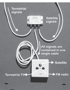
When installing a satellite dish, it can be quite tedious to pull a separate cable from the attic to the living room. There are combining filters that make it possible to use the same cable for the satellite i.f. signals as for the terrestrial signals from the aerial on the roof.
At the other end, in the living room, a special wall outlet can be used that contains a filter that separates the signals again. However, there is one disadvantage in doing this. It is not possible to supply the terrestrial in-house amplifier with power from a remote power supply in the living room. This is because the DC connection in the cable has to be used for the DC supply and polarization voltage control to the LNBs. Therefore the in-house amplifier, if any, must be supplied with power using a power supply that is located ahead of the combination filter for the satellite signals.
Figure 9.30 shows a combining filter and the outlet with the separation filter. The outlet looks like an ordinary wall outlet, but there is an extra F-connector connector on top of the two other connectors for terrestrial TV and FM radio. This new connector contains the satellite signals as well as the DC connection needed to operate the LNBs.
FIGURE
9.30
A separate combination filter for the satellite and terrestrial signals. The wall outlet separates the satellite and terrestrial signals again.
Figure 9.31 contains a combination filter that is also a combination filter for the terrestrial VHF and UHF channels.
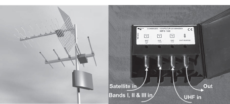
FIGURE
9.31
A combination filter from Danish manufacturer Triax that also combines the terrestrial VHF and UHF signals.
As shown here, there are possibilities to reuse existing cables. However remember that the satellite signals require low attenuating cables. If the existing cables are low–quality, you may have to exchange them for new ones. In addition, if there are severe problems, such as the need to use the cable for remotely powering the in-house amplifier, a separate cable will have to be added to the system.
THE TELEPHONE AND COMPUTER NETWORKS
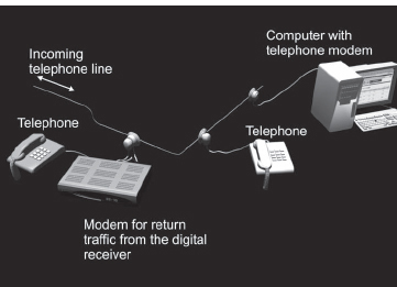
The telephone network once was only used for the telephones. But now the telephone lines are used for computer modems as well as broadband ADSL modems (see Figure 9.32). Another application is for the modems built into the digital receivers for ordering NVOD (Near Video On Demand) movies from pay TV operators, even though such services also may be ordered using the mobile phone. A problem might be to extend the telephone line so that you get a cable that reaches all the way to the digital receiver. Today it is quite easy to connect an extension cable to the telephone line since telephones use RJ11 connectors and the extension cables use the same kind of connectors. The simple trick is to buy a female-female RJ11 connector that allows two extension cables to be connected together.
FIGURE
9.32
The telephone cabling in your home may be used for computer modems as well as modem-equipped digital receivers and, of course, for the telephones.
The broadband ADSL modem is also connected to the telephone line. This technology uses radio signals that are above the spectrum used for speech in the copper wire telephone line. These radio signals are sensitive when traveling through a medium and the copper wire is not that well suited for radio waves. There is a filter that is used to separate the radio signals from the telephone signal that must be placed at the first telephone outlet. Otherwise, the cabling in your house will affect the ADSL signals and reduce the maximum bitrate you can get from your Internet connection. Another reason is that in some countries in the outlets, there is a secrecy function disconnecting the following outlets as you pick up the phone. This is to prevent people from listening to a phone in the other room. And of course, if you connect your ADSL modem to one of the following outlets, your Internet session might interrupted if someone else uses the phone.
THE HOME COMPUTER NETWORK
Following the ADSL modem the next home network, the Ethernet computer network begins. The Ethernet connection on your ADSL modem is normally connected to a combined firewall and switch. In some cases, the modem may have these functions integrated.
Sooner or later, you get a bunch of computers in your home. As you buy a new one, which probably happens quite often, the surplus computers are still in use somewhere in the house. Therefore the switch associated to the ADSL modem quickly becomes very important. You want to reach the Internet from everywhere in your house. At the same time you also get the opportunity to interconnect your own computers.
I will not go into all details about how to design a home computer network. But as has been discussed in Chapter 7, “Digital TV by Broadband,” the computer network and the Internet connection opens up a lot of new possibilities as adding media players and media centers that are connected to your TV sets as well. There are also other special devices in the market, such as IP radio sets that are really audio-only media players. In many cases it might also be interesting to use a wireless LAN solution, at least if you are not interested in pulling cables everywhere. Perhaps the future is not optical fiber in the home but no cables at all. WLAN and Blue Tooth solutions are probably only the first steps in that direction.
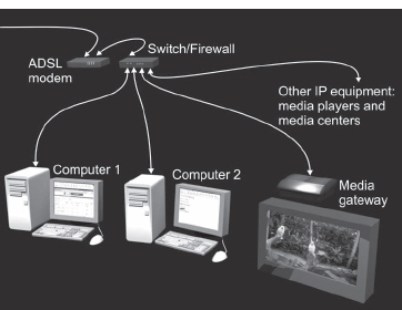
FIGURE
9.33
The home computer network can connect computers as well as different kinds of media centers, media gateways and media players.