3 |
Satellite TV |
| CHAPTER |

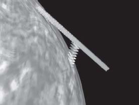
FIGURE
3.1
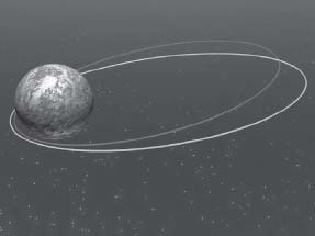
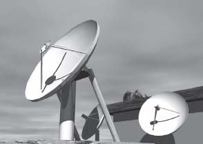
Satellite TV is based on space technology.
Since the dawn of man, the horizon has been the limit of visual observation. At the end of the nineteenth century, humans started to get interested in radio waves, and quite soon it became evident that the horizon was still an obstacle for the propagation of this new means of communication.
In the early days of radio, only low frequency and long wavelength signals were used. These signals are reflected into the atmosphere and can reach beyond the horizon. That's why it is possible to receive radio from distant stations in the long-, medium-and shortwave frequency bands. Unfortunately, the reception is not very reliable, since the atmospheric conditions vary with time of day and weather. As an example, it is easy to listen to radio station from all of Europe in the medium waves at night while reception tends to be more local during the day. The same applies to short-and medium-wave reception all over the world.
In the 1950s, television was introduced in most European countries. Since a TV signal contains about 250 times as much information as a radio channel, more frequency space was required. To get access to more bandwidth, it is necessary to move to higher frequency ranges. However, radio waves at higher frequencies have the disadvantage of not being reflected in the atmosphere and propagate into space instead. The only solution is to locate transmitters close enough to each other that reception from beyond the horizon is never necessary.
FIGURE
3.2
Radio waves at lower frequencies are reflected in the atmosphere in a random way. Radio waves at higher frequencies are not to a larger extent reflected in the atmosphere. In order to allow for broadband services, such as television, higher frequency bands must be used in order to get bandwidth that is large enough.
The higher the transmission towers are, the further the distance to the horizon will be, and the larger the area with a free line of sight from the transmitter will become. There are practical limitations for the maximum height of a transmission tower. In Europe there are many towers with a height of about 300 m (1,000 feet). This corresponds to the height of the Eiffel Tower in Paris. A 300 m transmission tower will cover a circular area with a radius of about 50 km (30 miles).
Constructing even higher transmission towers increases the coverage, but it is difficult. The tallest transmission tower ever built was in Poland and reached a height of 646 meters (2,120 feet). Twenty-five years after it was constructed, the tower collapsed during repair work. The tallest transmission tower today is in North Dakota and reaches a height of 628 meters (2,063 feet). TV transmission towers are the tallest buildings that have been constructed by the human being so far.
It is quite obvious that there are practical limitations for the height of transmission towers, but it would be desirable to get access to a much higher tower than the highest that has ever existed. There were early ideas about putting radio transmitters into aircraft and balloons. But keeping an aircraft or a balloon on location for years would have been impossible from a practical point of view.
In the October, 1945, issue of the radio amateur magazine “Wireless World,” Arthur C. Clarke, who later became one of the most well-known science fiction writers, described something completely new. He claimed to have found a way to put a satellite in orbit around the Earth. The satellite would seem to be located at a stationary point in the sky relative to a specific location on the surface of the Earth. This would be the equivalent of an immensely high transmission tower.
The word satellite means “follower.” A body of matter that is in orbit around the Earth also follows the Earth in its orbit around the sun. The moon is such a follower and orbits the Earth in slightly less than one month (perhaps the source of the name “moon”). The distance to the moon varies depending on its position in the Earth's orbit, but is at an average of about 384,400 km (238,855 miles). The time required to orbit the Earth at this distance is 27.3 days. An object in orbit around the Earth at a smaller distance will also make one turn in less time. An example of this is the space shuttle, which is in orbit at a height of about 300 km (186 miles) and circles the Earth in about 90 minutes.
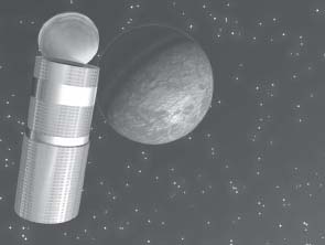
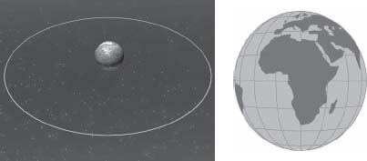
Sir Arthur Clarke's ingenious idea is based on the assumption that there must be a distance from Earth where the satellite will orbit the planet in 24 hours. The distance is approximately 36,000 km (22,370 miles), which is about one-tenth the distance to the moon. Since the diameter of the Earth is about 1,200 km (746 miles), it would be possible to fit three globes in between the satellite and the Earth, as shown in Figure 3.3.
In order to get the satellite to move in an orbit that is synchronous with the rotation of the Earth, the orbit has to be parallel to the Earth's equator. The satellite must also move eastward and be at the distance of the geostationary orbit, 36,000 km (22,370 miles). If these conditions are all fulfilled, the satellite will appear to be in a fixed position in the sky in relation to any point of the Earth's surface.
Note
During the decades that followed, the world witnessed several more examples of Arthur C. Clarke's imagination and genius. In “Year 2001 – A Space Odyssey,” he described a future spaceflight to Jupiter. This story was filmed at the end of the 1960s by Stanley Kubrik who was also ahead of his time. Clarke was finally raised to nobility for his feats.
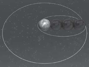
FIGURE
3.3
The geostationary orbit is at a distance of 36,000 km (22,370 miles) from the Earth.
The big advantage of a radio transmitter in a geostationary orbit is that about 40 percent of the Earth's surface will have a free line of sight for the satellite. This is a significant difference to what may be achieved from a transmission tower located at the surface of the Earth. Since there is an optical free line of sight between the satellite and the receiver, much higher frequencies can be used. When transmitting from satellites, the microwave frequency bands, which have much more bandwidth than terrestrial frequency bands, are used. By the end of this chapter, we will take a closer look at how many channels may be transmitted simultaneously from each orbital position of the geostationary orbit.
However, there is no use in having a satellite that cannot be controlled from Earth. There also has to be a feed with programs that are transmitted from a ground station. This feed is called the uplink and the signal returning to Earth is the downlink (see Figure 3.4). In the satellite, there is a frequency conversion of the incoming signal. It is not possible to use the same frequency in the downlink as in the uplink.
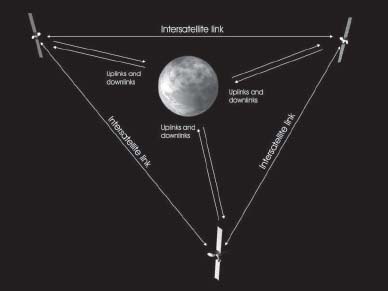
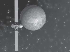
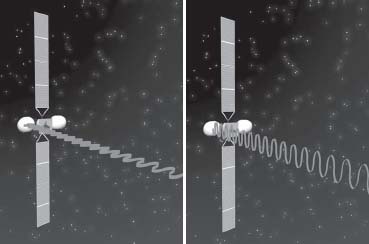
But one satellite is not enough to cover the entire surface of the Earth. In his first article on geostationary satellites, Arthur C. Clarke suggested a system of three satellites that could communicate with each other, as in Figure 3.5. The three satellites together cover all of the Earth, except a limited area around the poles (where there are almost no humans at all). By communicating between the satellites, it will be possible to communicate between almost any points on Earth. These “intersatellite links” are not today used for TV distribution but they are of great importance for other professional and military purposes.
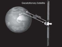
FIGURE
3.4
The signal from Earth toward the satellite is the uplink and the signal route back down again is the downlink.
FIGURE
3.5
Already in his first article in Wireless World, Arthur C. Clarke anticipated the future use of “intersatellite” links.
One use is the communication between space stations and space shuttles and ground control. Manned spacecraft usually cruise above the Earth's surface at an altitude between 300 km (186 miles) and 600 km (372 miles), which permits communication with at least one of the three satellites. In Houston, at NASA Mission Control, only one antenna is needed to be in contact with one of these satellites and maintain constant contact with the astronauts. Previously, communications stations were needed all over the world in order to ensure continuous communication. Of course, this kind of satellite systems has a great military importance in order to be able to communicate with low-orbit spy satellites.
THE ROUTE TO ORBIT
Launching a satellite into orbit around the Earth is not that easy. The Germans developed the first long distance rockets during the World War II. The man in charge of all this was Werner von Braun, who, after the war, got to manage the development of American rockets in the space race against the Russians. Ultimately, he was in charge of the Saturn rocket of the Apollo project that led to getting the first man on the Moon.
Almost 19 years after Arthur C. Clarke's article about placing a satellite in geosynchronous orbit, this feat became a reality. In August, 1964, the first geostationary satellite, Syncom 3 was launched.
To use a minimum amount of fuel at launch, it is necessary to choose a location as close to the equator as possible. The French space consortium Arianespace uses a base in Korou in French Guyana, in northeastern South America. The location is just some 5.3 degrees north of the equator, making it a very suitable place for launching geostationary satellites.
If an orbit is not in the same plane as the equator, it is said to be inclined. If a satellite is launched from a location directly on the equator, it is possible to send it directly into a non-inclined orbit by launching it either straight to the east or west. It is also possible to launch the satellite into any inclined orbit by choosing another direction.
If the satellite is launched from a non-equatorial location, the satellite cannot be launched into a less inclined orbit than the latitude of the launching site because the center of the orbit must coincide with Earth's gravitational center.
When launching from the pad in French Guyana, the primary orbit will be inclined by at least 5.3 degrees. To compensate for the inclination and get the satellite into a non-inclined orbit it is necessary to use an upper rocket stage. The larger inclination, the more fuel will have to be used and the larger the launcher has to be. For this reason, the closer the launch site is to the equator, the smaller and cheaper the rockets can be.
In the U.S., the geostationary satellites are normally launched from Cape Canaveral in Florida. The latitude is at about 28.5 degrees and the orbits will be much more inclined than is the case from the French base at Korou. Somewhat larger launchers are used to compensate for the greater incline.
The Russians had big problems in getting their first geostationary satellite launched. It was not until 1976 that the Soviet Union launched its first geostationary satellite for distribution of TV, EKRAN-M. The location of their base in Baikonur in Kazakhstan, at a northern latitude of 45.6 degrees, was one of the challenges.
Putting a Satellite in Orbit
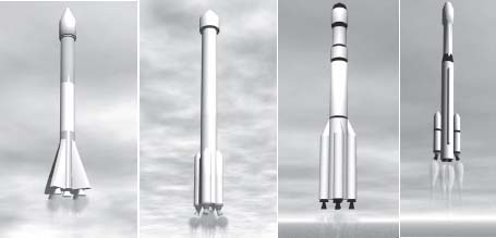
We will now take a closer look at how a satellite launch can be done. For this example, I have selected a launch using the now retired Ariane IV rocket that was used at Korou. This was a rocket especially popular to launch geostationary satellites.
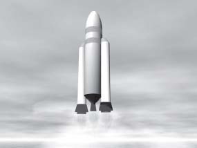
The rocket had a height of 60 m (197 feet) and included three stages. The first and second stages used fluid oxygen and other fuels, while the third stage used a combination of liquid oxygen and hydrogen. This is an extremely explosive combination.
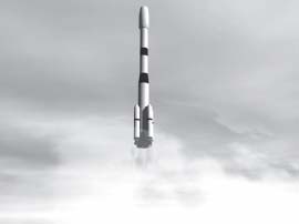
Ariane IV was capable of launching two satellites simultaneously, if one of the satellites was smaller. In these pictures, the launch of two medium size satellites is shown. A large thunder breaks loose as the giant rocket start to move upward. It is now T + 10 seconds, right at the start of the spaceflight. The giant first stage is assisted by four solid fuel rocket boosters to clear the tower. Solid fuel boosters are very good at providing a large thrust for a short time.
Quickly after clearing the tower, the rocket turns to the east as it passes over the Atlantic. Since the rocket is above water, it is easier to handle the falling rocket stages and boosters. And if anything should go wrong, it is also possible to let the rocket explode without causing too much damage.
FIGURE
3.6
T + 10 seconds: An Ariane IV rocket has just cleared the tower.
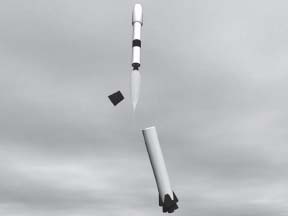
At T + 1 minute and 7 seconds, the four solid rocket boosters are jettisoned and fall into the Atlantic. They have now done their job, providing that extra thrust necessary in the first stage of the launch. The first stage continues to add more speed to the equipage until it reaches an altitude of 85 km (53 miles), when it shuts down and the second stage takes over. We are now at T + 3 minutes and 35 seconds. The idea of using several stages is that it is possible to get rid of used parts as the rocket reaches higher altitudes and speed. This reduces the weight and makes it easier to continue acceleration of remaining parts using less fuel.

FIGURE
3.7
T + 1 minute and 7 seconds: The solid rocket boosters are dropped.
FIGURE
3.8
T + 3 minutes and 35 seconds: The first stage is separated.
At T + 4 minutes and 45 seconds, the rocket is at an altitude of 118 km (73 miles). For comparison, the ordinary cruise altitude of a commercial airliner is at about 10 km (6 miles) and the Concorde cruised about twice as high. At an altitude of 118 km (73 miles), the atmosphere is very thin and the faring that covers the satellites can be jettisoned. The air resistance protection provided by the faring is now less than the cost of its weight.
FIGURE
3.9
T + 4 minutes and 45 seconds: The protective faring is jettisoned to save weight.
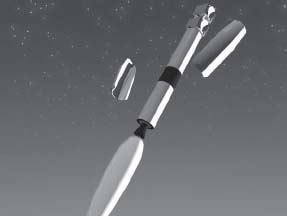
At T + 5 minutes and 58 seconds, the second stage is shut down start to fall back into the atmosphere. The third stage will burn for about 12 minutes and is now in charge of getting the two satellites into their orbits. The altitude is now about 150 km (93 miles) and the primary task of the third stage is to increase the speed rather than to further increase the altitude.
FIGURE
3.10
T + 5 minutes and 58 seconds: The second stage is separated.
At about T + 18 minutes, the third stage has finished its burn at an altitude of about 250 km (155 miles). The remaining parts of the rocket and its cargo are now in geostationary transfer orbit (GTO). The final actions are now to separate the two satellites from the rocket.
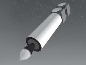
FIGURE
3.11
T + 17 minutes and 46 seconds: The satellite and rocket reaches geostationary transfer orbit and the third stage shuts down.
FIGURE
3.12
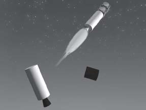
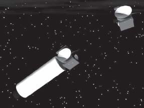
T + 24 minutes and 25 seconds: The first satellite is separated.
FIGURE
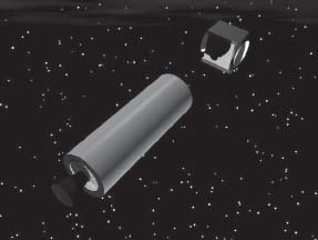
3.13
The second satellite is separated. The launch is a success.
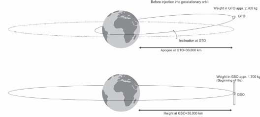
Both satellites are now in a geostationary transfer orbit. They will remain in this orbit for a few days while all systems are checked and until the satellites are in an appropriate position for the next phase, the injection to geostationary orbit (GSO).
FIGURE
3.14
Both satellites safely in their own geostationary transfer orbit.
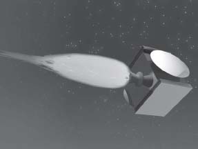
In the satellite itself we can find the forth stage, the apogee engine. The apogee is the uppermost point of an elliptical orbit. The lowest point in an elliptical orbit is called perigee. In order to obtain optimum result, the apogee engine is burned when the satellite is at its apogee. A lot of fuel will be consumed during this operation. A large satellite weighs about 4,000 kilograms (8,800 pounds) at launch. Almost half of this weight consists of fuel that is used to circularize the geostationary orbit into a pure geostationary orbit and to get rid of the inclination.
In addition to this, there is fuel for station keeping of the satellite throughout its lifetime. Since the equatorial plane of the Earth is leaning in relation to the orbital plane of the solar system, the other planets and the moon will make a pull on the satellite. All these gravitational powers slowly pull the satellites into inclined orbits if no station keeping maneuvers are done.
An average satellite lifespan is 10 to 15 years. The consumption of fuel used for station keeping varies but may be in the range of 25 kilograms (55 pounds) per year.
FIGURE
3.15
The satellite must gain more speed to get from geostationary transfer orbit, GTO, into geostationary orbit, GSO. The orbit also has to be adjusted to get rid of the inclination.
FIGURE
3.16
The apogee engine is fired to adjust the satellite into geostationary orbit.
Ariane V: the latest rocket technology
During the last years, efforts have been made to develop more powerful rockets. The most efficient choice of fuel is the combination of liquid oxygen and liquid hydrogen. The space shuttle is a good example of this technique. The shuttle has an external fuel tank containing liquid oxygen and hydrogen that is transferred to the main engines of the spacecraft. In addition to this, there are two solid rocket boosters with solid fuel. The successor of Ariane IV, Ariane V, also is based on similar principles.
FIGURE
3.17
The new generation of launchers, such as Ariane V, uses liquid oxygen and liquid hydrogen as fuel.
Initially, the goal of the Ariane V project was to make a rocket that could make European manned missions a reality. However, the budget has not been big enough to allow for these projects. Instead European astronauts have to go with American or Russian spacecraft.
LAUNCH VEHICLES FROM ALL OVER THE WORLD
Apart from the space shuttle, the Americans have based their launchers on old designs that have been in use for decades when launching from Cape Canaveral. Both the Atlas and Delta rockets have been used for many years but the designs have been continuously updated in new models and versions. In space industry, relying on old designs is not considered wrong—proven designs are regarded as more reliable than new and untested technology.
In the beginning, the intention was to use the space shuttle to launch satellites, but this plan proved not to be very economical. There is no real use to bring along astronauts to do “simple” missions like launching a communications satellite.
Since the breakdown of the Soviet Union, the Russians have been struggling to commercialize their space industry. Russia has an agreement with Kazakhstan to continue to use their Baikonur base to launch satellites (using reliable Proton-type rockets) and manned spacecraft. On top of this, Russian rockets are used in the new Sea Launch system that will be described later on.
FIGURE
3.18
From left to right, the American Atlas IIA and Delta II, the Russian Proton K rocket, and the Chinese “Long March.”
Today, the Chinese have their own launcher, the “Long March.” They have also started their own manned missions. The Chinese astronauts are called “taikonauts.” The Russian astronauts are called cosmonauts. Thus far, there is no special name for Europeans in space.
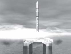
Sea Launch
A very exciting new initiative is Sea Launch—a very unconventional way of launching a satellite. The basic idea is to launch the rockets at sea in an area that is right on the equator and in a region with stable weather conditions. Combining Norwegian oil rig technology with Russian rockets and other space technology from Boeing, this seems to be a winning concept.
This concept is very favorable when it comes to aspects of security. It is possible to choose an area where there is quite little ship traffic and the launching company does not have to pay any government because the launch takes place in international waters.
FIGURE
3.19
Sea Launch has made it possible to launch geostationary satellites from a spot right on the equator.
STABILIZING SATELLITES
Once a satellite is in orbit around the Earth, it must become a stable platform for radio equipment. To get it all to work, the satellite must be in a stable orbit and the antennas must always be perfectly aligned with Earth, providing the right coverage areas.
Spin Stabilized Satellite
A simple way of avoiding uncontrolled tumbling of the satellite in space is making it spin. Anything spinning becomes stable around its spinning axis. A good example is a toy top spinning on the table. As soon as the top is spinning, it balances on the sharp point that is in contact with the table or the floor. Another example is a bicycle, where the large wheels spin and form two spinning axes that won't lean. This is why it's easy to ride a bike without focusing on the balance once you have reached a certain speed. A spinning axis does not want to change direction.
A spinning satellite consists of a cylinder that spins around its own axis. On top is an antenna that spins in the opposite direction. This is necessary since the antenna always has to point towards Earth. Spin stabilized satellites have always been regarded as being very reliable and still today this kind of satellites are still manufactured. A spin stabilized satellite is rotating around its axis about once a second.
One limitation of spin stabilized satellites is the number of transponders (the equipment required to distribute one analog channel or a multiplex of eight to 10 digital channels) it can carry. Since about two-thirds of the surface of the satellite's solar panels is not exposed to sunlight, it is not possible to obtain as much energy as a three-axis stabilized satellites (covered in the next section). Therefore the number of transponders that can be fitted into a spin stabilized satellite is limited to about 15.
The designers of the spin stabilized satellites have tried to compensate for the power problem by adding an outside skirt with additional solar cells. This skirt can be pulled out as soon as the satellite is in orbit. However, the limitations are so great that other designs are preferred in order to get a higher output of power.
Figure 3.20 shows the Hughes HS 376. The total height of the satellite in orbit is about 8 m (26.25 feet).
Three-Axis Stabilized Satellites
Using the three-axis stabilized satellite technology makes it possible to build much more powerful satellites. The attitude of a three-axis stabilized satellite is computer controlled. This computer controls momentum wheels that can be accelerated or slowed down to control the attitude by means of inertial forces. In weightlessness, only inertial forces and the use of thrusters will make anything move in a certain direction. We have to completely rely on the mechanical laws of inertia.
FIGURE
3.20
Hughes HS 376 is the most common spin stabilized satellite platform.
The three-axis satellite always turns its Earth panel towards Earth. On the Earth panel, the antennas are mounted and point towards the desired coverage areas on the Earth's surface. In order to make this possible, the satellite platform has to make one turn around its own axis every 24 hours.
The main idea of using three-axis stabilized satellites is that the solar panels, mounted on two giant wings extending north to south, can be turned by servo motors to keep their broadsides pointed toward the sun. This maximizes the possibilities to obtain and store solar energy, enabling the satellite to contain more than twice the number of transponders of a spin stabilized satellite. The average three-axis stabilized satellite has a wing span of about 25 m (80 feet) and can hold more than 30 transponders (carrying 30 multiplexes).
There are even larger satellites. The Hughes 702, with a wing span of almost 46 m (150 feet), can house up to 72 transponders. However, some companies believe it is better to split up their transponders on several platforms as protection if anything should go wrong. In addition, technology continues to develop and a large number of digital TV channels may be contained even in smaller satellites. So there might not really be a need for those really large satellites, at least not at present.
Hughes is not the sole manufacturer of satellites in the world. There are other manufacturers in the U.S. and Europe, though the number of companies that have been able to survive in the increased competition is not that many. The rapid technical development in the industry has forced them to form larger consortiums.
FIGURE
3.21
A three-axis stabilized satellite as the Hughes HS 601 is much more advanced and complicated than a spin stabilized satellite.
Satellite Life Expectancy
The largest problem with satellites is keeping them in the correct orbit, which requires thrusters to maintain the geostationary orbit.As mentioned earlier, satellites are placed in order with a supply of fuel for these adjustments; that fuel is generally expected to last for 12 to 15 years. There are techniques to reduce the fuel consumption, such as using an ion propulsion system. This system accelerates ionized fuel using electricity from the solar panels. In this way, the impulse created by the fuel is much larger than using conventional thrusters.
But the satellite manufacturers are not interested in developing satellites that have more than 20 years of life. The satellite manufacturers do not want to destroy their markets for the future. Therefore, the fuel reduction is used to decrease the weight of the satellite instead.
And there are also other things that would limit the lifetime of the satellite when the fuel problem is solved, such as the transmission equipment. The TWTs (traveling wave tubes) that are used for generating the transmission power have a limited lifespan, though there are some spare ones aboard the satellite. Another problem is the number of times that the onboard batteries may be recharged and the decreasing power of the aging solar panels.
SATELLITE PAYLOAD: THE TRANSPONDERS
All signals that are to be transmitted by the satellites have to originate somewhere. The satellite signals are transmitted from uplink stations that often use quite large antennas. In the antenna, the uplink power is concentrated into a narrow beam that is directed towards the satellite.
The uplink signals are generally transmitted at very high frequencies. Frequency bands that are used in Europe are 14 and 18 GHz.
FIGURE
3.22
The signals are transmitted towards the satellite using an uplink station. The uplink antenna is quite large and concentrates the uplink power into a narrow beam directed straight to the satellite.
Digital TV channels each have a very low bitrate, so they have to be collected into multiplexes to fill a complete transponder. The satellite transponder is a radio channel with a bandwidth of about 30 MHz. In the analog era, an FM-modulated TV channel would fill an entire transponder. Today 8 to 10 channels (or more) fit into a DVB multiplex that results in a total bitrate between 38 and 44 Mbit/s, which is suitable to fill the transponder bandwidth. One single TV channel uses about 4–5 Mbit/s.
Figure 3.23 shows the principal design of a satellite transponder.
The uplink signal is received by a parabolic antenna directed towards Earth. The first thing that happens inside the satellite is that the received signal is amplified. However it is not possible to retransmit the signal in the same frequency band as the uplink, so the signal is down-converted into the downlink frequency band. In Europe normally frequencies in the range 10.70–12.75 GHz is used. Finally, the downlink signal is amplified to an output level between 50 and 100 watts before the signal is beamed back to Earth using a downlink parabolic antenna on the satellite. In today's satellites, it is possible to use the same antenna for reception as well as for transmission in the satellite.
FIGURE
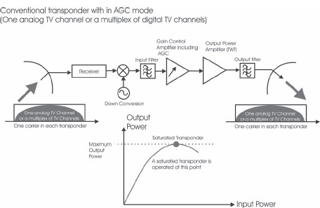
3.23
The principle design of a satellite transponder.
The performance of the satellite transponders are, to a large extent, decided by the transmission tubes. In most satellites traveling wave tubes, TWTs are used. These tubes work very much like other kinds of amplifiers. If the input power is increased so is the output power.
If the output power is quite low, the tube operates in its linear mode. If the output power is increased and we get closer to the maximum output power (the curve showing the output power versus the input power), the tube will bend and we get into the non-linear region of the tube's operational curve. The tube is said to be saturated when it is at maximum output power. Since this is the maximum output power of the tube, it is desired that the tube operate at this point when making transmissions to the general public so they can use the smallest antennas possible.
However, there is a problem in using saturated amplifiers. As can be seen in Figure 3.23, the output power as a function of the input power is not a straight line at the top of the curve. As a result we can only have one carrier in the transponder in order to get this to work. If we had several carriers in the transponder in non-linear mode, the carriers would mix with each other, causing intermodulation problems. Then new, unwanted signals would have appeared in the transponder. The effect is similar to what happens if you turn up the volume of your audio amplifier to its maximum—it doesn't sound very good. This is due to the occurrence of intermodulation products that are created inside the audio spectrum.
So it is necessary to have only one signal in the transponder. In the analog days, this was no problem since there was only bandwidth enough to house one TV channel in each transponder. But now, digital TV requires the multiplexing of several channels into one carrier to fill the entire transponder. Multiplexing means combining the bit streams of several digital TV channels into one single bit stream and is covered in Chapter 4.
Another transponder feature is the gain control amplifier that has an AGC (Automatic Gain Control) facility. The AGC keeps the output signal of the transponder at a saturated level, even if the incoming signal on the uplink is attenuated due to rain or other problems at the uplink station site.
Satellite Frequencies and Capacity
The satellites that distribute TV in Europe operate within the downlink frequency range of 10.70–12.75, a frequency range that is 2050 MHz wide. Each transponder occupies about 30 MHz of bandwidth. A very common bandwidth is 33 MHz.
Terrestrial broadcasting transmissions are limited to the frequency range below 1 GHz (1000 MHz). This means that each satellite orbital position gets more than twice the bandwidth than terrestrial systems.
The frequency range between 950 and 2150 MHz is called the L-Band. This frequency range is used to transport the signals from the parabolic dish into the satellite set-top box that is located close to the TV set. We will dig deeper into this in Chapter 4, “Digital TV by Satellite.” We will also take a look at the terrestrial frequencies in more detail in Chapter 5 “Digital TV by Cable,” and Chapter 6, “Digital TV by Terrestrial Transmissions.”
Satellites have a giant frequency range. Not only is the frequency range twice that of terrestrial systems, it is actually (in the European case) four times larger than the terrestrial frequency ranges because of the polarization isolation of antennas that can be used for transmission and reception in the microwave bands is very high.
Therefore, satellites can use the same bandwidth twice. The satellites transmit both horizontal and vertically polarized signals and the available frequency range is doubled to a total of 4100 MHz. (More on polarization in Chapter 4).
Due to this, it is possible to fit 160 transponders in each orbital position over Europe. Of course, this means you need more than one satellite, because most satellites cannot house more than 30 or 40 transponders. While 160 transponders could have been used to transmit 160 analog channels, with digital technology they can easily carry between 1,200 and 1,600 channels. In the years to come, the numbers will be increased even more due to new and better compression techniques.

FIGURE
3.24
Frequency bands that are used for satellite transmission in Europe. (Appendix B covers the North American frequency bands.)
FIGURE
3.25
By using both horizontal and vertical polarization the frequency range may be used twice.
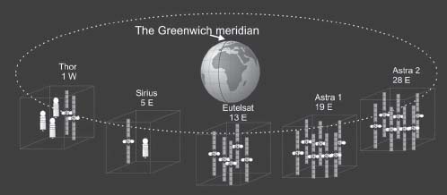
Every orbital position can contain a vast number of TV channels. But in addition, to this there are lots of orbital positions. The satellites are located like a string of pearls around the Earth's equator. One way to tell the position of a geostationary satellite is by the longitude of the site on ground that is right below the satellite on the equator.
The longitude divides the Earth into 360 degrees around the equator of the
Earth. Zero degrees longitude is at the longitudinal line that passes through the observatory at Greenwich just outside London, called the Greenwich meridian.
If you move south from Greenwich until you end up at the equator, you will be right below the orbital position of 0 degrees. At this special orbital position, you will find a very special satellite, the Meteosat Atlantic satellite. Meteosat is a satellite-based weather surveillance system and you have probably seen weather pictures from this satellite. Then you have also gotten a glimpse of what the Earth looks like as seen from a geostationary satellite.
The orbital positions are calculated in degrees east and west of the Greenwich meridian, as the longitude of the point at the equator that is straight below the satellite.
FIGURE
3.26
The geostationary orbital positions are based on the longitude of the location that is straight below the satellite on the equator. The vertical lines mark longitude and the horizontal ones mark latitude.
Distance Between Satellites
A very common question is if there is any risk of collision between the satellites if there are in the same orbital position. An orbital position is not a small area, but rather a very large cube in space. The orbital position is really a “controlling box” approximately 100 km (60 miles) on each side, within which the satellite is allowed to move. Since station-keeping maneuvers are done only once every two weeks, the satellite is allowed to move within this quite extensive area.
With this large controlling box, it would have to be a coincidence (and really bad luck) for two satellites to get dangerously close to one another. But still, some security rules have been installed. For two or more satellites share the same orbital slot, they must be built by the same manufacturer and have the same ground control system. If two satellites of different kinds are to be colocated, they will have 0.2 degrees of separation. The satellites really are not in the same orbital slot, but would seem to be when using quite small antennas.
The next problem is what distance is required between two orbital slots in order to be able to use the same frequencies. The answer depends on the antenna size used for reception on ground. Large antennas have more narrow beams than small antennas. For professional satellite traffic, an orbital separation of three degrees has been chosen. This will work fine down to an antenna diameter of about 90 centimeters (3 feet). If even smaller antennas are used, there is a risk for inter-satellite interference. Smaller antennas will require a larger separation angle.
FIGURE
3.27
The geostationary orbit, as seen from space, along with its control boxes.
Satellite Antennas
The satellite illuminates the Earth's surface as a spot light would, and it is possible to direct the beams towards the desired countries and regions. The larger the antenna, the more narrow the beams and the smaller areas may be selected to be covered.
In the early days of geostationary satellites, it was not possible to launch and control large antennas in space. The coverage areas were very large and the power was spread over a big area. In combination with low output power from the satellites, it became necessary to use extremely big antennas on ground.
Today the transmission antennas in the satellites are parabolic dishes with a diameter of one and two meters and smaller areas on the Earth's surface can be covered with the larger antennas. An antenna of about 1 m (3.2 feet) in diameter will cover the whole of Europe if transmission is in the Ku-Band (12 GHz). Smaller areas, such as individual countries, are covered by antennas about two meters in diameter (6.6 feet).
During the 1990s, it became possible to shape the beams to follow the contours of the continents. This is now achieved by deforming the circular reflector in a way that deforms the beam from the antenna in a controlled way. The most fascinating thing is that the manufacturers today have computerized simulators that are able to predict what the beams will look like as soon as the satellite is in orbit if the reflector is deformed in a certain way.
Satellite Coverage Areas
The two main competing satellite systems in Europe are SES Astra and Eutelsat. Astra has two orbital slots, 19 degrees east and 28 degrees east. The 19 degrees east slot contains a mix of European channels, with the German channels most prominent. The second slot contains a wide representation of English-language channels.
Eutelsat's main position, the HOT BIRD position, is 13 degrees east. Here you will find a lot of Italian channels but also channels from other South European countries. Eutelsat has a giant fleet of satellites and has also bought some regional satellite systems.
There are still some smaller regional satellite systems. Some of them are partly owned by the larger satellite operators.
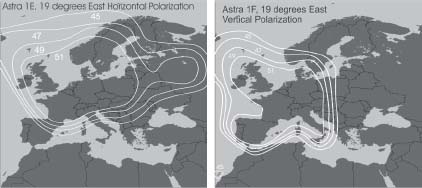
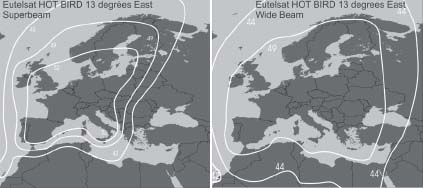
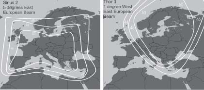
Figure 3.28 through 30 show some typical coverage areas for some important European satellites. In these maps, the signal strength is indicated by curves representing different signal levels. Chapter 4 provides a closer look at how to read these maps and decide what dish diameter is required to receive signals from the satellites. The weaker the signal, the larger dish is required.
FIGURE
3.28
Examples of coverage areas for Astra's main orbital position, 19 degrees east.
FIGURE
3.29
Examples of coverage areas for Eutelsat's main orbital position, 13 degrees east.
FIGURE
3.30
Examples of European coverage areas for two of the more regional satellite systems: Sirius at 5 degrees east and Thor at 1 degree west.
WHAT IS THE EQUIVALENT ISOTROPIC RADIATED POWER?
In the coverage diagrams, the curves indicate the signal strength from the satellite at different locations (comparable to height curves on a map). The signal strength is expressed in a unit called Equivalent Isotropic Radiated Power (EIRP). An isotropic source of radiation is a radiation source that radiates the same amount of power in all directions. The sun is an example of an isotropic source of radiation (see Figure 3.31).
FIGURE
3.31
The satellite only has to produce a narrow cone of power. This is the reason why the TWTs of the satellite still can produce high EIRP levels.
If we are standing at a location on the Earths surface experiencing a certain radiation level from the satellite, the EIRP is the output power of a radiating source that would radiate the same power as we are experiencing but in all directions simultaneously. But a satellite is not an isotropic radiator. It uses an antenna to focus the transmitted power towards a limited area on the Earth's surface. This means that the EIRP can be much stronger than the actual output power of the satellite.
The reason why we are making a comparison with an isotropic radiation source is because such a source is well defined (a reference that simply radiates in all directions). The unit used for the EIRP in the coverage maps is called dBW. Watt (W) is a way to express power. Decibel (dB) is a figure representing a relationship. In this case, it is the relationship to the power of 1 Watt.
A relationship in linear scale may be recalculated to the decibel scale according to the formula in Table 3.1.
3.1
The relationship in dB scale = 10 * Log, The relationship in linear scale, where Log stands for the 10-logarithm.
| Watts | Decibels |
| 1 W | 0 dBW |
| 2 W | 3 dBW |
| 4 W | 6 dBW |
| 10 W | 10 dBW |
| 100 W | 20 dBW |
| 1,000 W | 30 dBW |
| 10,000 W | 40 dBW |
| 100,000 W | 50 dBW |
| 1,000,000 W | 60 dBW |
The measurements you find in the coverage areas are around 50 dBW, which would correspond to 100,000 W. But it is obvious that a satellite transponder having an output power of about 100 W (the power consumption of an ordinary light bulb) cannot produce an output power of 100,000 W.
As discussed above a satellite is able to transmit this large amount of power towards a certain location because 100 Watts of output power is concentrated within a narrow beam using the transmitting antenna, rather than being sent off in all directions. With an output power of 100 W it is possible to achieve a high EIRP within a limited area using a directional antenna as is the case in a satellite.
Chapter 4 describes what diameter is required at different EIRP levels. A simple rule is that 51 dBW corresponds to a diameter of 60 cm (2 feet) and 45 dBW corresponds to a diameter twice as large, 1.2 meters (4 feet). Chapter 4 also includes more coverage diagrams and tables showing the relationships between EIRP and dish diameters.