11 |
The Home Cinema |
| CHAPTER |
FIGURE
11.1
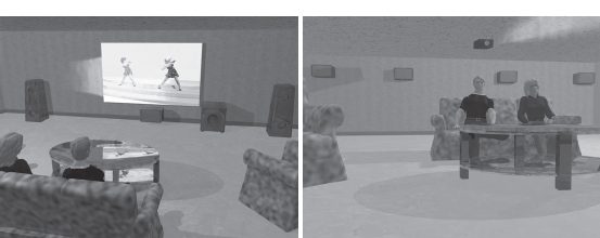
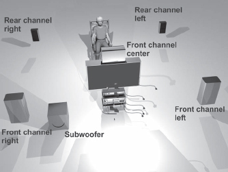
For some, the dream scenario for a home cinema might be a high definition projection system combined with a 7.1 multi-channel audio system.
By the end of the 1990s, the development of the TV set had gone so far that the home entertainment electronic industry started to search for something new and different. The more TV channels, the more movies. Movies are a good way of filling program hours. But movies are at their best at the cinema. Why not try to create a more cinema-like environment at home, one that is adapted to movies rather than conventional TV? The basic ideas behind the home cinema were born.
HOME CINEMA DISPLAY COMPONENTS
A home cinema is a system of devices or you may even regard it as a system of sub-systems of devices. First, we have to have some kind of display system. To get as close as possible to a cinema configuration, a projection system is the best choice.
However it has to be dark in the room for a project system to perform adequately. The alternative is a back-projection TV set, but the picture is not as bright and sharp as in a cathode ray tube. The solution that will be most common in the future is probably large plasma or LCD screens. As of today, these screens are quite expensive for the general public.
Therefore, the cathode ray tube is still the most common display system since it provides a sharp and intense picture with good contrast ratio at a low price.
Cathode Ray Tubes
Cathode ray tubes, CRTs, have been used since the late 1930s and have developed considerably since then. The black and white CRT became the color CRT, and the latest developments have been 100 Hz tubes that remove some of the typical flickering in CRTs. Another important development was the introduction of 16:9 format, (widescreen) CRTs. The 81-cm (32-inch) size has become especially popular, since it is regarded as a replacement for the old 74-cm (29-inch) 4:3 set.
Of course it is possible to build your home cinema based on an 81-cm (32-inch) CRT TV set. But it is hard to get a larger picture. There are also used to be 91-cm (36-inch) 16:9 CRT sets, but they were very big, bulky and heavy. Conventional CRTs are not the way of the future. To get a larger picture we have to try to find other means, such as flat-panel sets and home projector systems.
Flat-Panel TV Sets
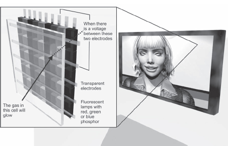
For decades people have dreamed about a flat television that can be hung on the wall like a painted picture. That seems to have become a reality at a price that is getting more and more affordable. The larger sets are mostly plasma screens, where each pixel consists of one red, one green and one blue fluorescent lamp that is very tiny. Each pixel is in reality just a small cell containing an ionized gas that lights up when an electrical field is built up around it by a grid of electrodes that reach all pixels of the screen (see Figure 11.3).
FIGURE
11.2
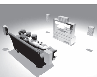
This 81-cm (32-inch) CRT TV set combined with a 5.1 multi-channel audio system, including two rear channels, has been a very common home cinema system.
FIGURE
11.3
The technology behind a plasma display. (See color plate.)
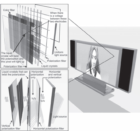
The competing technology is the LCD, Liquid Crystal Display, which is based on having a giant fluorescent light source behind the screen (See Figure 11.4). In front of the lamp, there is a polarization filter that makes the light have just one polarization. Then there is a second grid of tiny liquid crystal polarization filters. The light polarization angle of these crystals is changed when there is an electrical field put on the crystals. This electrical field is created by a grid that reaches all the liquid crystals (similar to the grid in the plasma display). As the polarization angle changes more and more to get at right angles to the light from the rear fluorescent lamp, it is possible to block the light at a single red, green or blue part of a pixel. There is also a filter in the rear, giving each part of each pixel a red, green or blue color.
FIGURE
11.4
The technology behind an LCD display. (See color plate.)
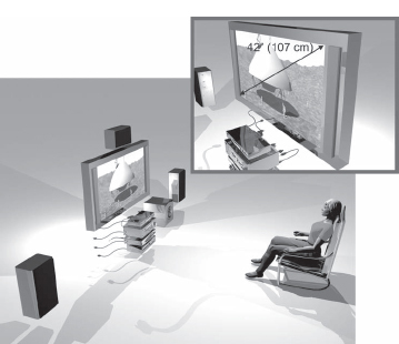
The plasma screen is based on each pixel emitting its own light while the LCD display is based on each pixel being able to block out light. Today it is more expensive to produce large LCD displays than plasma displays. On the other hand, there are limitations to making small plasma displays—it is hard to make tiny pixels that emit light. For that reason, the market from 107 cm (42 inches) and up is dominated by plasma displays and the market for smaller flat-panel TV sets is ruled by the LCDs. But LCDs have started to compete efficiently, even in the larger sizes, and the 102-cm (40-inch) LCD panel will probably be one of the most common display systems during the next few years.
FIGURE
11.5
The 107-cm (42-inch) plasma display is probably the most common flat-panel TV, but the 102-cm (40-inch) LCD is a strong competitor.
Projectors
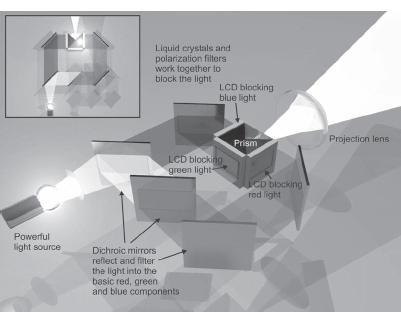
The most cinema-like pictures are obtained from projectors, because they can generate the largest pictures. Like flat-panel displays, there are two alternatives. The most common alternative is an LCD that works with each pixel blocking or revealing the light depending on its polarizing characteristics, as in Figure 11.6. In many cases, there is an LCD matrix for each color: red, green and blue. There are two basic problems in using LCD. The first is that the contrast ratio is limited and the second is that since the strong light of the lamp must pass through the LCD, it can overheat and be ruined.
FIGURE
11.6
In LCD projectors, there are often three separate LCDs for each color. (See color plate.)
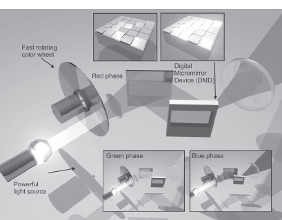
The competing technology is DLP, digital light processing and consists of a matrix with hundreds of thousands small mirrors whose orientation can be affected by electrical signals in the same way as the pixels in plasmas or LCDs. The micro-mirror chip is generally called DMD, for digital micro-mirror device. By pointing the mirrors in the right direction, the light from that pixel will be exposed on the projection screen. It is very similar to when you are traveling by car and suddenly get a reflection of the sun in a window that happens to be in the right angle to reflect the light straight towards you. The advantage in the DLP technology is that the contrast ratio in the picture will be much better than for LCD. The risk for the device to be over-heated by the light source is also much lower than in LCDs, since the light is reflected. This also makes it possible to use very bright light sources. In most cases only one DLP is used to produce all three colors. The three basic color pictures are produced in sequence by letting the light pass a rotating wheel with filters corresponding to the three basic colors (see Figure 11.7).
An alternative to a projector is a back-projection TV set. These devices are based on the same principles as all other projectors, but the sets become quite large. Therefore this technology has had big problems competing, especially with plasma displays.
FIGURE
11.7
The DLP is based on a small chip with micro-mirrors. Controlling the angle of the mirrors determines whether a certain pixel will be bright or not. (See color plate.)
One of the largest drawbacks of projectors is the expensive replacement lamps and noisy fans.
Super-Slim CRTs and OLED Displays
However, there is a chance that the CRT technology may survive against all flat-panels and projectors. New super-slim CRTs are under development and manufacturers say they will be able to produce very cheap and slim CRTs that have better performance than the competing plasma and LCD technologies. Another strong competitor to the plasma and LCD displays might be OLED (Organic Light-Emitting Diode) displays that will provide much thinner displays than ever before.
A problem affecting plasma screens, LCD displays and projectors is the compatibility with high definition transmissions. In Europe, it has been decided that TV sets and monitors that can reproduce the 720p and 1080i formats are said to be “HD Ready.” 720p means 720 lines with progressive scan and 1080i is 1080 visible lines with interlaced scan. There will be more on HDTV in the next chapter.
ASPECT RATIOS
The most difficult problem when watching movies using conventional TV sets is that the picture format is too wide. The relationship between the width and the height of the picture is called the aspect ratio.
As early as the 1950s, the wider movie formats were introduced. Today movies presented in the cinema use the aspect ratio of 2.35:1 (i.e., that the picture is 2.35 times wider than the height of the picture). Most television sets have an aspect ratio of 4:3 (equivalent to 1.33:1), which means that the movies are too wide to fit on the television screen. When movies that are filmed in wider formats are to be presented on TV screens, something has to be done to accommodate the difference in aspect ratio.
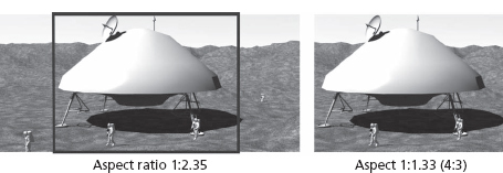
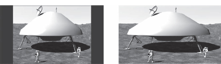
The most common way to handle this used to be pan and scan. In this system, an operator would manually selects the most interesting part of the picture for display on the 4:3 TV screen. Using just the center part of the picture does not work very well. This means that the left or right edge (or a little of both) is trimmed off for TV viewing (see Figure 11.8).
FIGURE
11.8
Pan and scan means that the presently most important part of the cinemascope screen (2.35:1) is selected to be presented within the 4:3 (1.33:1) 11.8 window.
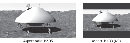
The alternate solution is letting the viewer watch the whole scene. This means the whole image is reduced to fit the full width of the image, and black bars are added to the top and bottom of the screen, as in Figure 11.9. This format is called “letterbox” format. The advantage is the viewer will see everything, but the drawback is that a large portion of the screen is left just black and a large number of lines in the signal are not used. This is a waste of capacity in the transmission system, really, and it results in worse resolution in the picture.
FIGURE
11.9
In the letterbox format, black bars are added to change the aspect ratio of the image.
The problem of having different aspect ratios is an old one, as old as Cinemascope and Panavision movies. Pan and scan and letterbox have been in use for decades, but letterboxing has been enjoying increased popularity recently.
Widescreen TV sets are becoming quite popular in Europe and North America. Widescreen TV sets have an aspect ratio of 16:9 (1.78:1) instead of 4:3 (1.33:1). The new widescreen television aspect ratio is still not as wide as the cinematic format (2.35:1) but it is a compromise between these two worlds. Since 16:9 is much closer to the cinematic format, the problems involving different aspect ratios are reduced.
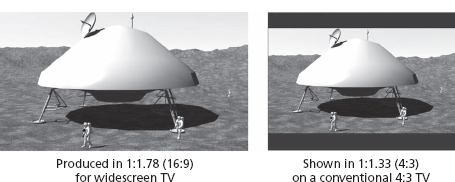
However, as long as there are some TVs that are not widescreen sets, there will be problems. A program that is produced in the new 16:9 format has to be presented in the letterbox format on a conventional 4:3 format TV (see Figure 11.10). Even if the difference in aspect ratio is not as great as when a movie in the cinematic 2.35:1 format is to be shown, the picture will get smaller than if the program had been produced in the old 4:3 format.
FIGURE
11.
A program that is produced in the 16:9 (1.78:1) format will be presented in letterbox format on a 4:3 (1.33:1) TV set.
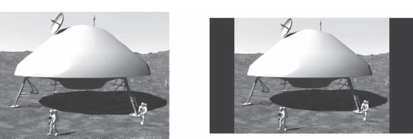
The most common CRT widescreen TV has an 81-cm (32-inch) picture diagonal. This is the size that usually replaces an old 74-cm (29-inch) 4:3 format TV, which has a picture diagonal of 74 cm (29 inches). If a production in the 4:3 format is to be presented with the original aspect ratio, it has to be letterboxed on the side. For this reason, the 4:3 picture will get smaller in an 81-cm (32-inch) widescreen TV than if shown on a conventional 74-cm (29-inch) TV screen.
FIGURE
11.11
A conventional 4:3 format picture on a 74-cm (29-inch) 4:3 format TV set (left) will be larger than the same picture on a 81-cm (32-inch) widescreen TV (right) 11.11 with the correct aspect ratio for the transmission. The pictures are to scale.
In a widescreen TV, there are possibilities to make automatic as well as manual change of aspect ratio. Most people that own a widescreen set choose to use the complete screen all the time without taking the transmitted aspect ratio into account. Strangely enough, the average viewer tends to get used to having the wrong aspect ratio when watching 4:3 transmissions. The picture will get stretched, as shown in Figure 11.12. However, there are some different tricks to reduce this problem. One of these methods is to avoid stretching the middle part of the picture where the viewer keep his sight most of the time.
FIGURE
11.12
The correctly letterboxed 4:3 format picture on a 16:9 widescreen TV (left). If the entire screen is to be filled when receiving a 4:3 format picture, the picture will get deformed when it is stretched horizontally (right).
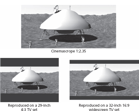
The advantages of using a widescreen TV set are most evident when watching movies. A movie that is transmitted using the letterbox format will provide a larger picture in an 81-cm (32-inch) 16:9 set than on a 74-cm (29-inch) 4:3 set. However, since the movie is already wider than the 16:9 screen (2.35:1), there will still be black panels above and below the picture on the widescreen TV set.
FIGURE
11.13
A cinemascope picture 2.35:1 is considerably larger on an 81-cm (32-inch) 16:9 TV set than on a conventional 74-cm (29-inch) 4:3 format TV set. The figure shows the correct proportions between the sizes of the screens.
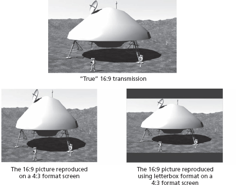
In digital transmissions, the programs are normally transmitted in true widescreen format. True widescreen means that the picture is pressed together horizontally if watched on a 4:3 format screen. On the widescreen TV set, the picture is stretched into normal proportions again.
Figure 11.14 shows the picture in a true 16:9 transmission on a 16:9 format screen. At the bottom, you can see how the picture is presented on a 4:3 format screen without and with letterboxing. The problem is opposite the one we had when watching a 4:3 transmission on a 16:9 screen. In that case, the picture was horizontally stretched. In this case, when a 16:9 transmission is to be presented on a 4:3 format screen, the picture is horizontally compressed. The alternative is creating a 4:3 picture in the letterbox format.
FIGURE
11.14
A true widescreen transmission will get pressed together horizontally if shown on a conventional 4:3 TV set.
How Program Companies Handle Compatibility Problems
It is obvious that the program companies want to produce as much of their content as is possible in the new 16:9 format. And of course they also want to have movies in their program schedules. They also want as many viewers as possible to enjoy their broadcasts, no matter what kind of TV sets the viewers use. The solution is to letterbox the programs produced in the 16:9 format into the 4:3 format when using analog distribution systems, such as analog terrestrial transmitters or in analog cable. This makes the proportions to look right on a conventional 4:3 TV set. And most viewers have learned to accept the letterbox format when they watch a movie. The drawback in doing this is that people who have 16:9 widescreen sets have to zoom in on the picture to get rid of the black panels on top and at bottom of the picture. The result is a lower-resolution picture.
In digital broadcasts, the 16:9 format is used instead. Then people with widescreen sets will make maximum use of the signal and all visible lines will be used to provide optimum resolution. In the video signal there is also a signal, the WSS (wide screen signaling) that tells widescreen TV sets whether the transmission is in widescreen format or not.
However, if the viewer has a 4:3 TV set, the conversion into letterbox adapted for the 4:3 format will take place in the digital receiver itself. And if you receive a digital signal, you have to have a digital receiver. The same thing applies to DVD players where you can also set the format of the output video signals to suit your TV set. If the picture is not converted into letterbox format, the picture will be compressed (having the wrong proportions) when presented on the 4:3 screen.
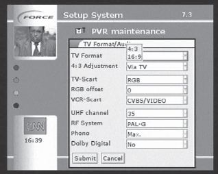
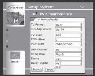
There are reasons for checking the settings in your DVD player and your digital receiver (see Figure 11.15). If you have a mix of 4:3 and 16:9 sets connected to the same digital receiver there might be a lot of switching in between the formats. Some digital receivers have a shortcut for this on the remote. Some of the latest 4:3 sets also have a built-in feature to produce letterbox from a widescreen format transmission. This might be another way of solving a part of the problem of having a mix of 4:3 and widescreen sets connected to the same digital receiver.
FIGURE
11.15
Many digital receivers and DVD players enable you to select the desired aspect ratio.
CONNECTING HOME CINEMA COMPONENTS
In a home cinema system, it is important to get the maximum picture quality. To get a sharp picture with pure colors, the digital receiver should be connected using the RGB interface rather than the composite video. Using the scart connector, you will get the RGB signals if you select it in the TV format menu, as shown in Figure 11.15.
The digital receiver is based on primarily providing the component RGB signals. These signals are then encoded into an ordinary PAL signal, which has lower quality but is more convenient for connecting to a VCR or to a RF modulator for additional connections through the aerial inputs of the TV sets.
In the scart connector of the digital receiver, you have access to the composite video and the component RGB signals which is shown in Figure 11.16. If you choose to use the RGB signals, the receiver will put a voltage on a separate pin to tell the TV set to feed the screen with these input signals. It is quite obvious that by using the RGB interface, the signal will pass the shortest route through the receiver, avoiding the PAL encoder of the digital receiver as well as the PAL decoder of the TV set (Refer back to Chapter 2, Figure 2.10). In addition, the screen is going to be fed by RGB signals anyway.

FIGURE
11.16
The composite and component RGB signals are available in the scart connector. The RGB signal provides the best picture quality. (See color plate.)
Note
The worst picture quality is achieved by using the built-in RF modulator in the digital receiver or the DVD device. The signals will not only have to pass through the PAL encoding and decoding circuits but also through the modulator as well as the tuner and demodulator circuits in the TV set.
More Advanced Ways to Connect Components
If you have a projector, a plasma or LCD TV you might have other alternatives—even better than RGB—to connect your display system.
Many DVD players have (Y,Pb,Pr) component connections. This way of connecting the display system requires three separate cables for the luminance and the two chrominance difference signals. Using the component connections, it also becomes possible to use progressive scanning (where the lines are drawn one after the other and not every second line as is the case for interlaced scanning). Progressive scanning provides a picture with less flickering.
The most advanced ways of connecting display systems are DVI and HDMI connections that provide digital interconnection. However these connections are only available in more expensive DVD devices, HDTV disc players and digital receivers for HDTV. The same applies for the analog component connections.
DVI and HDMI is the definitely the route for the future, at least when it comes to high quality connections in home cinema systems (more on HDTV in the next chapter).
HOME CINEMA SOUND
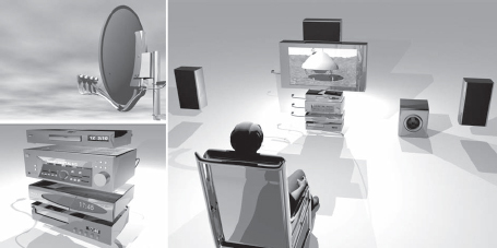
The next part of the home cinema is the sound system. A sound system for home cinema use is quite different from a conventional stereo system. The sound is multi-channel and there might be six to eight speakers, ensuring that the sound comes from different directions, just as in reality (see Figure 11.17).
FIGURE
11.17
The home cinema sound system has six or more separate channels.
Multi-Channel Sound
The home cinema is not just a large quality picture; it is also a matter of high-quality sound reproduction. The difference between a home cinema sound system and a conventional two-channel stereo system is the number of audio channels. Any sound system that involves more than two sound channels is called multi-channel.
My first encounter with multi-channel sound was in the beginning of the 1970s when I discovered the button marked “Ambio phonic” on my stereo amplifier. Two additional speakers could be connected on the back of the device. According to the instruction manual, it was possible to get some kind of “spacious” sound if two extra speakers were connected. I became very curious and, after a while, purchased two additional speakers and soon a three-dimensional, spacious sound started to spread around the room.
The ambio phonic sound utilized phase differences in the audio signals of the right and left front channels to create both rear channels. My amplifier did not contain four separate amplifiers; it was a “cheat” four-channel system.
At about this time, the record companies started to introduce four-channel stereo. There were at least three different systems in the market. The simplest system, adopted by CBS, was called SQ and was based on the previously mentioned phase differences between the front channels. The rear channels were extracted from the basic two channels and used separate amplifiers. There was also a competing system called QS which worked in a similar way.
Finally there was a “real” four-channel system called CD-4. CD-4 had nothing to do with compact discs. Instead it was a system that put a sub-carrier above the audible spectrum containing both rear channels. Thirty years ago, it was quite hard to store more than two channels on a mechanical vinyl record.
The analog record player needle can only move in two directions: horizontally (left/right) and vertically (up/down). Using the combination of these two directions of movement, it is possible to encode two channels into the mechanical track of the record. This was the only way to separate the two channels, but there was always inevitable crosstalk between the channels. The CD-4 system was a real four channel system for long play records but never became widespread. To get the CD-4 system to work, you also needed a special pick-up needle (“the Shibata” needle) and a very expensive decoder to extract the rear channels. The only really efficient way to store multi-channel audio (more than two channels) in those days was on tape and multi-channel tape recorders were not used by ordinary consumers.
The four-channel stereo systems disappeared as the 70s passed by, perhaps because people were quite satisfied with their newly purchased two-channel stereo system. Another barrier was the extra trouble required to pull cables to the rear speakers. The only place where four speakers became popular was in the cars.
In the early 80s, compact discs (CDs) made an appearance, and they were recognized as a very good medium for multi-channel audio. The main problem in analog multi-channel audio storage is getting sufficient channel separation. In digital systems, it is easy to get a 100 percent separation between the channels. By multiplexing signals in time, as is done in the DVB transport stream, it is easy to keep the signals separated from each other.
However, the multi-channel sound didn't make its comeback until the end of the 1990s. However this was not primarily a come back for reproducing music—it was a comeback for movie sound reproduction. It was the efforts of the movie industry to introduce multi-channel sound in the cinemas that led to the use of multi-channel sound in DVD recordings and TV transmissions. The first multi-channel system to be used for movies was an analog system quite similar to the SQ system of the old days, the Dolby Surround system.
Dolby Surround
Dolby Surround is analog multi-channel sound that only requires two channels as carriers. From these two channels, a center channel is created that fits right between the two basic front channels. The center channel contains the audio that is in common for the two front channels. This means the mono part of the signals, such as the singer or the actor, is located right between the basic right and left front channels. Having a center channel ensures that this audio content really will originate at a point right between the two other front speakers. In an ordinary two-channel stereo system, this channel is simulated by the front speakers and the location of the singer or actor might be affected by your own position in the room. This is not acceptable if the center channel must always originate from the same location as the TV screen, in other words the center channel is there to ensure that the dialog really comes from the same location as where you see the picture.
The rear channels are also created using the differences between the front channels. In reality, these channels are the same even though separate amplifiers are used for each channel. In this way, the Dolby Surround system is quite similar to the more or less simulated SQ and QS systems of the 1970s. The only real difference is that the two basic channels are much more in control using digital carriers, such as DVDs and DVB or NICAM stereo transmission.
However, there is a new channel on top of all this, the sub-bass channels that are fed to the sixth speaker, the “subwoofer.” The subwoofer channel is extracted from the two basic channels that are used as carriers. The subwoofer only reproduces the lowest frequencies of the audio spectrum and usually has its own built in amplifier. Some people say that this is the most important audio channel of them all. You can choose the volume and the frequency range to be reproduced by separate controls on the subwoofer itself.
Even though Dolby Surround is not a “real” multi-channel system, the movie industry has succeeding in using it in a believable way. By carefully encoding the differences representing the rear channels into the basic two channels, they are in control of the final output from the different speakers as the audio is presented in a cinema or in the viewer's home. Therefore movies and TV programs based on Dolby Surround give a much stronger impression than ordinary two-channel stereo sound.
The large advantage in using Dolby Surround is that any stereo storage or distribution system may be used. As a result, it is possible to record Dolby Surround on a conventional VHS Hi Fi recorder or to distribute Dolby Surround using the A2 or the NICAM stereo distribution systems for analog TV. This has meant a lot to the VHS movie rental business.
Another nice feature of the Dolby Surround decoder is that it can be used quite efficiently to simulate spacious sound from sources that are not Dolby Surround encoded. You might say that Dolby Surround is a way to keep old two channel recordings alive.
A digital receiver will provide excellent two-channel stereo sound. These sound channels may be used as excellent carriers for the Dolby Surround sound and therefore most TV stations distribute the Dolby Surround versions of the movies if available.
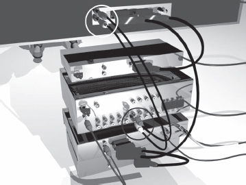
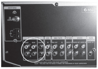
A TV set uses several analog sound sources. In addition to the analog sound that is received by the TV set itself in A2 or NICAM stereo, there are scart connections from the VCR, the DVD recorder and the digital receiver. Undoubtedly, the simplest way to connect a home cinema amplifier to the TV set and always get audio that is coordinated with the video is to use the analog RCA connectors on the TV set (see Figures 11.18 and 19). Then you can be sure that whatever sound is associated with the program on screen will be played through your home cinema sound system as well. You will not have to change sound source on the home cinema amplifier when moving from one source of program to the next and you'll avoid a large number of cables.
FIGURE
11.18
A good way of connecting all analog program sources of your TV set to the home cinema amplifier is to use the analog output RCA connectors on the TV set.
FIGURE
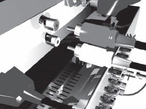
11.19
RCA connectors are the most common connectors for analog audio.
If there are no separate audio outputs on the TV set, separate analog audio cables have to be used between every device and the analog inputs of the home cinema amplifier. Many hours of soldering can be saved by buying ready-made cables with connectors.
Digital Multi-Channel Sound Systems
Using digital signals, it is easy to encode six or more separate audio channels into a DVD or into a digital TV (DVB) signal to create much more impressive sound than Dolby Surround. Therefore a digital receiver or a DVD device is an excellent program source for the home cinema.
Today there are two dominating digital multi-channel sound systems, Dolby Digital and DTS. Both systems have five separate audio channels and a sixth channel containing the information for the sub-bass channel. This is called a 5.1 system—the five refers to the audio channels and the 1 refers to the reduced audio channel that feeds the subwoofer.
FIGURE
11.20
A digital receiver is an excellent program source in a home cinema system.
Dolby Digital
The Dolby Digital system is different from Dolby Surround in many ways. The six channels are now completely separated. The center and sub-bass channels are also completely separate channels, with no cross talk at all.
Dolby Digital is the most common digital multi-channel sound system. A bitrate of 384 kbit/s is quite common. This is not much, since an ordinary bitrate for the two-channel stereo sound in a DVB transport stream is at 256 kbit/s. Another name for Dolby Digital is AC-3 (Audio Code 3). There is a new version of Dolby Digital, Dolby Digital Plus that provides more efficient encoding. In this system the bitrate may be reduced to 256 kbit/s. This new system is an attempt to get more broadcasters to use Dolby Digital in their transmissions. Capacity costs money.
DTS (Digital Theatre System)
DTS Digital Surround is a lot of Dolby Digital. The largest difference is that DTS operate at higher bitrates. The fully feathered DTS signal is at 1,536 kbit/s but there are even less consuming versions at 768 and at 448 kbit/s.
My own opinion is that DTS is better than Dolby Digital. Unfortunately DTS is not as common as Dolby Digital, which is more or less standard on any DVD. When it comes to multi-channel audio distribution via satellite, cable and terrestrial transmitters, there are a number of TV channels that have Dolby Digital transmissions for the movies and some other programs. There are some test transmissions using DTS, but is seems that Dolby Digital is more popular since it is more economical when it comes to bitrate.
Multi-Channel MPEG Audio
There is a European standard for multi-channel audio within the frameworks of MPEG. In practice, this standard has not been successful in competing with Dolby Digital and DTS.
Any digital signal that is stored on a DVD or is a part of a DVB transport stream distributed via satellite, cable or terrestrial transmitter can be used to carry a multi-channel audio multiplex. This sound multiplex may be encoded according to any of the multi-channel audio standards that have been mentioned here.
The digital sound multiplex has to be fed to a decoder extracting the six analog channels that may then be fed into the amplifiers. However, as can be seen in Figure 11.21, there will be six separate audio connections between the decoder and the amplifier. Amplifiers with analog inputs for an external decoder like the one in Figure 11.21 are not that usual.
FIGURE
11.21
Lots of cables and connectors are required if a separate Dolby Digital or DTS decoder is to be connected to a home cinema amplifier using analog connections.
Instead, in most cases the decoders are built into the home cinema amplifier. Home cinema amplifiers have one or more digital inputs to take care of the complete digital multi-channel multiplex. There is a standard for this interface, called S/PDIF (Sony and Philips Digital Interconnect Format), that has become accepted everywhere. The S/PDIF connection can handle any kind of digital audio, even two-channel PCM linear encoded audio. The home cinema amplifier identifies which kind of digital audio format is available at the S/PDIF input. The kind of format identified is often presented on a display on the amplifier.
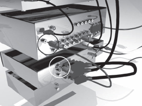
The S/PDIF connection exists in two versions, electrical and optical. The electrical version uses RCA connectors and a shielded cable (see Figure 11.22). Even a coaxial cable will do. The optical version is based on an optical fiber connection (see Figure 11.23). DVD players usually have an optical connection while electrical connections are quite common on digital receivers. It is even possible to buy opto/electrical converters if you do not have the right connection available.
FIGURE
11.22
An electrical S/PDIF connection between the digital receiver and the home cinema amplifier.
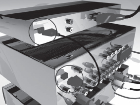
FIGURE
11.23
Optical fiber is used for the optical S/PDIF interconnection between the digital receiver and the home cinema amplifier.
Using the digital input of the amplifier means that the D/A (digital to analog) conversion takes place in the amplifier rather than the DVD player or the digital receiver. In most cases, the quality of the D/A converters are much better in the home cinema amplifiers than in the other devices, which means you will probably get better performance using the integrated D/A converters of the amplifier. This is also applicable for the two-channel PCM audio, so always use the S/PDIF interface whenever possible. The quality improves and the number of cables decreases.
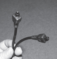
The optical S/PDIF connector is one of the few applications for optical fibers in consumer use. Nowadays it is easy to connect optical fibers. The light does not come from a laser but from a LED emitting conventional red, visible light. Use the optical cables with care. There is a small cap for protection of the connector that has to be removed before connecting the fiber. The connectors are called Toslink connectors (see Figure 11.24) and exist in different versions depending on what kind of devices are to be connected. It is essential to note that the optical cables can not be bent in the same way as electrical cables. There has to be a certain radius at each bend and you must treat the cables carefully.
FIGURE
11.24
Toslink cable for interconnection of optical S/PDIF interfaces.
Eventually, you might need a number of digital connections if you have a number of devices with S/PDIF outputs. Some home cinema amplifiers do not have an ample number of connections. Manual optical switches can be used to solve this problem. Of course, a manual electrical switch could also be used if you have electrical S/PDIF interfaces.
Digital Reception of Dolby Digital (AC-3)
Dolby Digital is well established on DVDs. However, some TV stations also have Dolby Digital multi-channel audio as a part of their service. In these transmissions, the AC-3 audio is encoded into a separate bit stream having its own PID in the DVB transport stream. The receiver must be able to detect that the digital multi-channel bit stream is available. Then this stream of bits has to be extracted and re-encapsulated according to the S/PDIF standard. The digital receiver has a menu where the viewer can select between using the ordinary stereo audio channels or the multi-channel audio (see Figure 11.25). The digital audio is then fed to the S/PDIF interface of the home cinema amplifier. The amplifier detects the signal and sends it to the appropriate decoder. Most of today's amplifiers have Dolby Digital and DTS decoders. From the decoders, the appropriate linear coded digital audio channels are sent to the D/A converters and then on to the appropriate amplifiers for the different channels that are connected to the speaker system.
FIGURE
11.25
Choosing two-channel stereo sound or the Dolby Digital multi-channel audio.
The DVB standard supports Dolby Digital transmissions. However, you must be sure that the receiver has both an S/PDIF interface and the firmware to handle Dolby Digital. If the receiver is not ready for Dolby Digital because of the firmware, a software upgrade may solve the problem. Today there are lots of European satellite channels that use Dolby Digital. One of the first European stations to use Dolby Digital was the German channel Pro 7. There are also a number of pay movie service providers that have adopted Dolby Digital multi-channel sound in their broadcasts.
An important thing to remember is that when using a separate amplifier for the audio, the sound and the video go separate ways. In the digital world of flat-panel displays, there are delays caused by image processing in the display systems. This can cause lip sync problems which can be solved by delaying the audio deliberately. This is covered in more detail in Chapter 12, “HDTV and the Future of Television.”
Even More Sound Channels
Most people would be satisfied with 5.1 audio. However, there are even higher versions of the multi-channel sound standards. In the 6.1 systems, there is an additional channel for it's a speaker located between the rear speakers and preferably a bit further back. The home cinema amplifier must have an additional output channel.
However, there might be problems finding a place for this rear center channel. The room for a system like this must be large enough to put the viewer more or less in the middle. Most people with a 5.1 system probably have their rear speakers located in the rear corners of the room and they sit where the rear center speaker should have been.
There are even 7.1 systems where there are two more rear channels and speakers.
The home cinema has awoken a new interest for sound reproduction at home. Not since the 1970s—when the stereo systems were introduced—have people been this interested in amplifiers and speakers.
PROGRAM SOURCES
As been discussed, there are several program sources that may be used for the home cinema. The most popular program source is undoubtedly the DVD player. But as soon as you have discovered the advantages in digital video, you also want the TV channels to be digital and you will probably buy a digital receiver and so on. Using large screen means you want less noise in the picture and therefore you will have to go digital.
If you can stand the noise, you can also continue to use you analog signal sources. NICAM stereo and Dolby Surround are capable of handling a lot just like your Hi Fi VCR, which may stick around for yet some years to come. And don't forget of your existing VHS cassettes.
But the home cinema is more than that. It is just as important to have a room with the right furniture and possibilities to make dark as it is to have the right equipment and programming. But it is still worth it, because it is the new gathering place for the family—the new bonfire where the stories of today are told. And that place is important.