1 |
The History of Television |
| CHAPTER |
Storytelling is really the foundation of our media society. Throughout the millions of years since the human beings learned to communicate with each other, the ways of expressing and storing information have changed. One of the latest additions to this is television—“a way to see in a distance.”
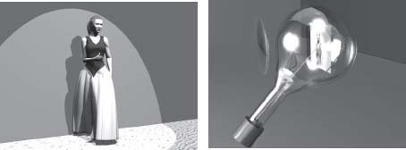
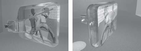
FIGURE
1.1
During the Stone Age, people were active during the day using their weapons and tools. At night, they sat around the fire telling stories.
FIGURE
1.2
Modern man is active during the day. Weapons and stone tools have been exchanged for computers and mobile phones and at night, people sit around the television, watching stories.
THE EVOLUTION OF STORYTELLING
Ever since the human language became a reality, telling and listening to stories have been the most loved activities for humans. Since the dawn of culture, we have been sitting around the campfire every night listening to the stories that have been passed from one generation to the next. In the beginning, the stories and fairy tales had to be remembered and be told from generation to generation. After a while, humans began to document the stories in drawings on stones and walls in caves. Later, skin from animals and paper were used. The intellectual heritage did not have to rely on the human memory any more and the stories could live on, unchanged, for an extended period of time. This is essential since otherwise the human brain has a tendency to gradually change the meaning of the story.
The introduction of the printed word, thanks to Johannes Gutenberg, made it possible for the stories to be mass-produced and brought to a large number of people. Cultural mass production became a reality. No technical device was required to read a book, but the knowledge of reading was necessary. The family of the nineteenth century gathered around someone who was reading aloud from a book.
For a very long time, storytelling was limited to spoken words and text. However, by the end of the nineteenth century, Thomas Alva Edison began to change all that. He invented the phonograph, which made it possible to record sounds on a wax-coated roll. Another invention from that same era—the telephone—made it possible for one human being to talk to another human being at a very large distance, a drastic change in the ease and immediacy of communication. These inventions are both based on the observation that sound consists of small vibrations that propagate through air due to small local changes in air pressure. These air pressure changes can be transferred to a thin membrane. The movement of the membrane can be used to form a track in a spinning roll of wax or disc made of a similar material. For the first time, it became possible to store sounds. Another way of using the membrane is to get an electrical coil to move in a magnetic field. Then an electrical current is induced in the coil and this current can be connected to another coil in front of another magnet at a completely different location, making another membrane move to recreate the sounds. The alternating current in the copper wire between the early telephones was one of the first electrical signals. These discoveries paved the way for the fantastic telecom and media technology of today.
By the end of the nineteenth century, some scientists and inventors also became aware of the existence of electromagnetic waves. Radio waves are radiated from stars and other natural sources. As all radio waves, artificially created radio waves propagate through air as well as vacuum by the speed of light. Actually, radio waves are very much the same phenomenon as light but have a much longer wavelength than visible light.
Inventors began to use the electrical signal to control the appearance of radio waves. By doing this, the radio wave became a carrier for messages and even the copper wires became unnecessary, even when transferring voice messages. In the beginning of the twentieth century, almost explosive changes occurred in the technology of spreading and storing stories told by voice. A few decades into the new century, it became possible for millions of people to listen to one person simultaneously telling them all the same story. Radio broadcasting was born.
The ways to record music and other sounds also developed rapidly. Recorded voices from these years still act like the time machine that never before existed in human history.
The art of storytelling has evolved from one person sitting at the campfire telling a story directly from his memory to someone reading from a book in a radio studio with nations of people listening. Today, the TV is undoubtedly the largest storyteller. Hollywood and program providers all over the world have taken over a large portion of the storytelling at home. The basic principles are still the same. You gather every night and watch and listen to stories; some are fictional and some are real. Some people today even have the campfire in their living room in the form of the modern fireplace.
THE HISTORY OF THE TV SET
The invention of television and the technological advances that have occurred in the last 120 or more years have introduced a number of systems, solutions and methods of broadcasting sound and images into viewers’ homes.
Mechanical Television (1880–1930)
As early as the end of the nineteenth century, some inventors were speculating about transferring pictures using electrical signals. Transferring sounds is quite easy, since a microphone provides an electrical signal that directly corresponds to the vibrations in the air that are caused by the sounds.
However, a picture is something much more complicated. Even a picture in black and white consists of a very large number of more or less luminous points that each provide a signal describing how light varies by time at that specific point. Transferring signals describing each point separately would mean a very large number of signals and would be practically impossible to implement. Some kind of compression of the information would be needed to decrease this large number of signals to just one signal describing the whole picture.
In 1884, German inventor Paul Nipkow got a patent for a mechanical device that could scan a picture. The device included a vertical rotating disc in which there were holes arranged in a spiral form. When a picture was projected against the disc, it was only possible for the light from one point at a time to penetrate the disc and to reach a photosensitive cell located on the other side of the disc. By spinning the disc, the light that penetrated the disc described the picture point by point. After one turn of the disc, the complete picture had been scanned. The electrical signal produced by the photosensitive cell is a primitive video signal. At the receiver end, a similar rotating disc with holes is used. This receiver disc rotates with the same speed as the transmitting disc. An electrical source of light that is controlled by the video signal is located behind the receiver disc. A picture can now be viewed in front of the receiver disc.
In those days, Nipkow was regarded as a very strange man with a very strange interest. However, his invention, the sequential scanning of a picture, is the basis for television, computer screens and digital photography. It is without doubt one of the largest inventions ever made when it comes to visualization.
You can also say that Nipkow laid the foundations for compression of electrical signals by simplifying the signals describing the picture to just one single signal with the scanning device. He did this to make the signal easier to transfer to the receiver. This simplified signal is still accurately perceived by the viewer because our brains process the signals from our eyes very slowly. Even though we only can see one point of the picture at a certain moment, we have an accurate experience of a complete picture, as long as the disc spins fast enough. In a corresponding way, the movement we think we see in a movie are really only a series of still pictures shown in a rapid flow.
Using the imperfections of our senses became one of the recurring methods during the further development of television.
Nipkow never succeeded in putting his TV system into practice. The electronic components required to do so were simply not available at the time of his invention. It was the Englishman John Logie Baird who implemented the first cameras and TV sets that really worked, in the 1920s. Baird started the first TV transmissions from England and produced kits for his mechanical TV set, called a televisor. Most of the kits were sold to radio amateurs all over Europe.
The picture on these televisors was very small and had very poor resolution. The Baird televisor was connected to the speaker output of an AM radio and the signal controlled the luminosity of a gleaming lamp located behind the perforated rotating disc. Audio was transmitted on a separate channel and received by another set. The transmissions from England were carried out in the medium wave band. The 25,000 kits that Baird succeeded in getting distributed were sold mostly to curious people, and the “technology” did not achieve widespread sales or use.
FIGURE
1.3
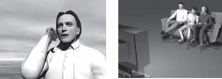
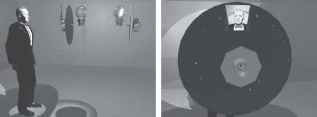
Mechanical television was a product of a mechanical era and produced the first electrical video signal. The worst problem was keeping the receiving and the transmitting discs synchronized with each other.
Electronic Television (1930s and 40s)
It was obvious from the beginning that mechanical television had to be replaced by something else before TV could become a commercial success for the general public and there were many experiments with different electronic solutions. A major invention was the iconoscope, a predecessor to camera tubes that was combined with new, improved TV systems. Using electronics made it possible to get TV systems with the picture divided into many more lines than before. As a result, the picture had considerably improved resolution.
Continued mechanical developments
Baird was almost certainly aware that electronics sooner or later would beat mechanical television, but he continued to try to develop mechanical solutions to compete with the electronic ones. By increasing the number of holes in the discs and (at a later stage) combining mechanics and electronics, he fought on in an untiring way. Finally, he even produced equipment for mechanical color TV by using discs with different sets of holes that had filters for the basic red, green and blue colors.
In the 1920s there was a great interest in developing electronic tubes to be used in radio sets.
The iconoscope was a kind of electronic tube. The electrons are accelerated towards an anode that consists of a light-sensitive material. The light-sensitive layer will increase its conductivity as it is illuminated and thus the current through the tube will increase compared to if the electron beam is hitting a non-illuminated area. The current through the tube will be proportional to the illumination of the specific point where the electron beam happens to hit (see Figure 1.4).
FIGURE
1.4
In the first electronic TV systems, the video signal was produced by an iconoscope where an electron beam swept across a projected picture of the subject.
Charged particles (such as electrons) are deflected when they pass through a magnetic field. Around the tube, coils control the beam both horizontally and vertically. In this way, it is possible to get the beam to scan the picture line by line. Electronic scanning can be made much faster than is possible in mechanical television making electronic television capable of handling a very large number of lines and a large number of pictures each second.
In the beginning, there were several television broadcast systems in use. North and South America decided to use a system with 525 lines and a picture rate of 30 pictures per second. The reason for the latter was the use of 60 periods AC. In those days, there was a large risk for picture disturbances if the picture rate was not an even multiple of the AC frequency. In Europe, 50 Hz AC is used and consequently the somewhat lower 25 Hz picture rate was selected.
In Europe, there were also different opinions about what number of lines should be used. Great Britain introduced an early 405 line system while France's first system had 819 lines (you could say that the French were ahead of time, using an almost HDTV system). Other parts of Europe introduced the current standard definition 625 line system right from the start. However not all lines are used for picture transmission. It takes some time for the electronic beam to jump from the lower to the upper part of the picture in order to start on the next picture frame. Therefore, in the European system, only 576 lines are active parts of the picture and 49 lines are in the vertical blanking interval. At a later stage, it was discovered that these lines could be used for teletext transmission.
The duration of each line is 64 micro seconds (64 millionths of a second). However, not even all of these micro seconds are used for picture transmission. The first 12 micro seconds are used for the electronic beam to jump from the end of a line to the beginning of the next one. This time interval is called the horizontal blanking interval.
When introducing electronic TV, synchronizing pulses were put in the horizontal blanking interval to tell the TV set when the beam should turn back and start to draw the next line. Another pulse was introduced in the vertical blanking interval to tell the set that the beam should start drawing a new frame. In this way, automatic synchronization was introduced and the viewer could relax in front of his TV instead of being occupied with manual synchronization of the transmitter and receiver, as in the days of mechanical television.
However, in the childhood days of television, there was yet another problem. On the receiving end, an inversed iconoscope, the cathode ray tube, was used. In the picture tube, the picture is produced by an electron beam that scans a surface of zinc sulfide which emits light when it is hit by the electrons (see Figure 1.5). In early cathode ray tubes, the light emitted by the zinc sulfide had time to go out before the whole picture was drawn. The result was a flickering picture. To prevent flickering, a technique called interlaced scanning was introduced, where only every other line is scanned. For example, 312.5 lines (of which 288 are active lines) are scanned before the beam starts on top again to draw the remaining lines. Each 312.5-line scan is a half picture and is called a picture frame. Thus the complete picture consists of two consecutive frames. These frames are displayed at a frame rate of 50 Hz, double the picture rate of 25 pictures per second. As a result, a much more stable picture was achieved without flickering. Another interesting consequence is that movements are actually displayed at a rate of 50 Hz, instead of 24 pictures per second that is the case for ordinary film at the movies. That is the reason why television seems—to the small percentage of people sensitive to these kinds of effects— to present movements in a more realistic way than film
The other kind of scanning is progressive scanning, where the complete picture is drawn in one single scan line by line. Progressive scanning first came into use in computer screens, by which time cathode ray tubes had evolved so there was no real need for interlaced scanning anymore. However, interlaced scanning has continued to live on in the televisions systems until this day.

FIGURE
1.5
In cathode ray tube for black-and-white television, the picture is drawn on a zinc sulfide surface that will emit light as it is hit by the electrons.
In the early days of television, there was no other media for distributing TV besides terrestrial transmitters. However, unlike radio transmissions, television needed more bandwidth to house all the information contained in the analog TV signal. The higher resolution pictures made possible by electronic television created a need for about 250 times more bandwidth than radio required.
The technique for transmission that requires the least bandwidth is amplitude modulation (AM), where the strength (amplitude) of the radio wave varies according to the voltage level of the video signal. Since television in Europe did not make its breakthrough until the 1950s, frequency modulation (FM) was selected for the audio sub carrier. Radio based on FM transmission became the normal way for distributing radio channels. FM makes it possible to distribute the signals in a way that is much less sensitive to noise and disturbances than AM is. However there is a cost: bandwidth.
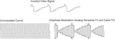
FIGURE
1.6
In analog terrestrial TV, amplitude modulation is used for the picture signal (the video). The audio is transmitted on a separate subcarrier that is frequency modulated.
COLOR TELEVISION (1950S AND 60S)
As we have seen already, Baird worked on a system for mechanical TV distribution in color. But it would take many years until color TV could be introduced to the general public.
A color picture is actually a combination of three pictures, each representing the color contents corresponding to each of the basic colors in the picture: red (R), green (G) and one blue (B).
In color television, the optical picture was divided into its three basic components using a prism or a set of mirrors and a number of color filters. Each picture component was focused on a separate camera tube (a more modern iconoscope). In today's cameras, the camera tubes have been replaced by solid state mosaics that produce the three electronic R, G and B signals.
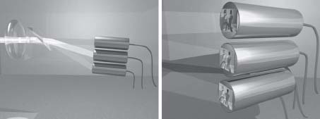
FIGURE
1.7
By using color filters or a prism, a picture can be separated into its three basic color components. (See color plate.)
In principle, it would require three parallel TV channels to distribute the R, G and B signals. However, this would result in a large waste of the scarce frequency ranges that are available for terrestrial transmission.
There is, however, a clever solution to all this. Our vision is only sensitive to sharpness when it comes to differentiating between dark and light. When it comes to colors, our vision does not require the same resolution it does for black and white, and we can do with a much more diffuse display of colors still believing that we are viewing a sharp picture.
Color TV Systems
The systems for color TV that were developed during the 1950s and 60s are based on a black-and-white picture that is transmitted at near full resolution. A European black-and-white picture requires approximately 5 MHz bandwidth. Of this, 1 MHz was removed in the upper frequency range of the video spectrum so that the black-and-white video signal occupies the spectrum between 0 and 4 MHz. In the spectral area between 4 and 5 MHz, a subcarrier is put around the frequency 4.43 MHz. The subcarrier contains information about which color (nuance) and how strong color (color saturation) that should be represented in each pixel. Since this color information will be held within only a fourth of what a black-and-white picture requires, the color signal has poor resolution. But this does not impact the final image transmitted, since the eye does not look for contours in color.
The color information is phase modulated, i.e., the phase angle of the subcarrier represents the color nuance while the amplitude of the subcarrier represents the saturation of color at that pixel.
The color subcarrier is compared with a reference signal that is updated on each line by being compared with a small portion of reference signal that is transmitted in the beginning of each line. This small portion of reference signal is called burst.
This system decreases the need of frequency space, making the color TV signal to fit within a common black-and-white TV channel, but it also provides full backward compatibility. This was important because it enabled the black-and-white TV device to receive the color TV transmissions though only in black and white. It would not have been very realistic, from an economical point of view, to have special transmissions to color TV devices in the 1960s.
The U.S. was the first to introduce commercial TV in color. The American system, National Television System Committee (NTSC), was introduced quite early and has been in use ever since. Unfortunately this system has a number of technical problems. One problem is keeping track of the color subcarrier phase when the signal is subject to reflections against buildings or mountains. These reflections cause the TV receiver to get one signal directly from the transmitter and one delayed, reflected signal. This can make the color tone in a human's skin change from bright red to green. An old joke is that NTSC really does not mean National Television System Committee but “Never The Same Color.”
The Germans took a step ahead in the mid-60s by introducing the Phase Alternating Line (PAL) system. The PAL system is quite similar to the NTSC system, but the phase reference is shifted plus or minus 90 degrees from one line to the next. This converts the color tone errors (caused by reflected TV signals) into color saturation errors, which the human eye is not as sensitive to.
The French invented their own system, Sequential Couleur avec Mémoire (SECAM). In this system, the phase stability problem is completely avoided by using frequency modulation instead of phase modulation, making the transmissions insensitive to reflexes.
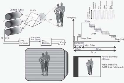
FIGURE
1.8
In the European analog system for color television, PAL, the color information is coded in a phase modulated subcarrier at 4.43 MHz. The phases of the carrier indicate the color tone and the amplitude symbolizes the saturation of the color. (See color plate.)
The color TV signal can be described in two different ways, as either a combination of the three basic color signals R (Red), G (Green) and B (Blue) or as a combination of the components Y, U and V. In the latter method, Y is the monochrome black-and-white signal while U and V are the two color difference signals that are contained in the color subcarrier. It is possible to get the R, G and B signals from the Y, U, V signals and vice versa by simply adding and subtracting the signals with each other according to certain algorithms.
Early Picture Tubes for Color TV
Unfortunately it was quite hard to manufacture a color TV picture tube in the early days of color television. The problem is that the tube must contain three electron cannons instead of one (as in the black-and-white tube). In addition to this, the inside of the tube must be covered with very small points of zinc sulphides that are doped with various types of pollutants in various ways so the three basic colors can be reproduced when the surface is bombarded with electrons.
The most difficult part is that the electron cannons can only illuminate their own respective points of sulfide. The solution to this problem is a plate containing hundreds of thousands of tiny holes. This plate is located between the electron guns and the sulfide dots, restricting the electrons from each gun to the dots that respectively represent the color of that gun.
If we have a group of three little dots—one red, one green and one blue— the total impression is black when none of the dots emit any light. If only one of the three dots is bright, we will see the color of that dot. If each of the three dots emits an equal amount of light, we will see white or a shade of grey, depending on the intensity of light from the three dots.
FIGURE
1.9
In a color tube, there are three electron guns instead of one as in a black and white tube (See color plate).
By letting each of the three dots emit a certain combination of light, any hue of color can be produced.
A VIDEO RECORDER IN EACH HOME (1970S AND 80S)
Since a video signal contains a lot more information than an audio signal, it took until the end of the 1970s until it became possible for average consumers to have a videotape player in their homes. A sound tape recorder can handle frequencies up to approximately 15 kHz, providing acceptable sound quality. A videotape player must be able to handle frequencies up to several MHz.
By the end of the 1970s, a war between standards for the competing technical solutions for home video broke out. Among the early systems were Philips VCR (Video Cassette Recording), Betamax from Sony and VHS (Video Home System). VHS ended up the winner after a number years of struggle where, among other things, Philips had time to introduce yet another system, Video 2000, that was more technologically advanced and actually clearly better than VHS. But, perhaps due the wide range of pre-recorded films on VHS, that system won in spite of its lower quality and greater cost.
The home video recorder gave the TV viewers a lot more freedom. Now, it became possible to view programs that were transmitted at inconvenient times. Sometime, two good programs conflicted on the two only Swedish channels that I could watch at that time, and it was the same in most European countries. There were only one or two state-owned channels on the air. With the video recorder, it became possible to record a program on one channel while watching the other. Then it became possible to watch the recorded program at a time when the content of both channels was boring. In those years much of the content consisted of political debates and other less interesting stuff and the video recorder became a relief.
CABLE TELEVISION AND DTH SATELLITES (1980S AND 90S)
The next big step in the development of television in Europe—already in use in the U.S.—was the establishment of cable TV, which provided more program choice than ever before. However, the satellites that were used for TV distribution in the early 1980s were quite weak. In Europe a dish size of about 1.5 meters was required for reception of the signal. This was too big for ordinary viewers to handle by themselves, so cable TV became very popular. But by the end of the 1980s, new and stronger satellites were introduced that could be used by consumers, so Direct-to-Home broadcasting became the new way to increase the number of TV channels in your home.
At the same time, it began to become too costly to expand cable TV to more households. The rest of the population in most countries did not live in blocks of apartments and it was expensive to include individual homes in the larger cable networks. With stronger satellites and more sensitive receiving equipment, it was possible to use smaller parabolic dishes and the satellite receiver became each household's property.
In the beginning of the 1990s most satellite transmissions were made using the same technology as for terrestrial TV, i.e., by using composite PAL signals in Europe and NTSC signals in North America. However there was an important difference. Instead of using AM frequency modulation, FM was used. FM only requires about one-tenth of the transmission power that would have been required for AM. This is important since power in satellites is scarce. The power has to be picked up by the solar panels and it has to be stored in onboard batteries that could provide power when the satellite goes into the shadow of the Earth.
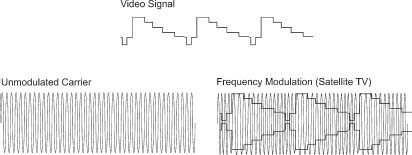
FIGURE
1.10
In analog satellite transmissions, frequency modulation is used.
MULTIPLEXED ANALOG COMPONENTS SYSTEM (EARLY 1990S)
Even if the PAL system has a better performance than the NTSC system, there are some technical problems. Both systems use composite signals including both the black-and-white (luminance) as well as the color (chrominance) signals. In other words, they contains all three color components in the same signal and a person wearing a shirt with a black-and-white check pattern could look like a person wearing a rainbow pattern shirt instead. This phenomenon is called cross color. On top of all this, the analog audio in TV transmissions was not that good since it was often spoiled by annoying interference from the video signal.
Large efforts were made in the 1980s to find a new, partly analog, TV system that would be better than the existing ones. The system chosen in Great Britain was the Multiplexed Analogue Components (MAC). The MAC system is based on the transmitting the black-and-white and chrominance components of the video signal in different time slots. The audio would be digital.
If we study a line in a MAC signal (which has duration of 64 microseconds), like the one in Figure 1.11, we can see that the first 10 microseconds are used to transmit the digital line synchronization word (a short, unique sequence of digital bits replacing the synchronization pulses of the old systems) and digital audio. Thus the line synchronization interval is used to transmit useful information, which is not the case in the analog PAL signal except from the PAL burst and the line synchronization pulse itself.
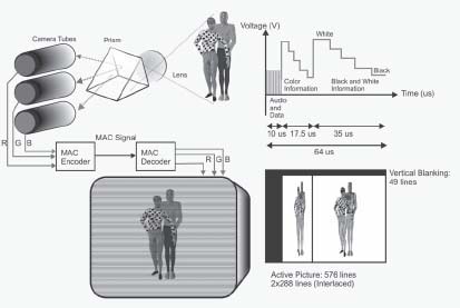
FIGURE
1.11
In the MAC system, the color components of the picture were separated by transmitting the black-and-white part of the picture in the beginning of each line and the color information was sent in the later part of each line. (See color plate.)
The next 17.5 microseconds are used to send the color information, where every other line is used for the U and V signals respectively. The remaining 35 micro seconds are used to send black-and-white (luminance) information. This means that the video signals are compressed and relocated in time as is shown in Figure 1.11. As a result, a MAC receiver was much more complicated than a PAL satellite receiver. All MAC signal processing was to be made digital and this was a step in preparation for the coming digital television systems.
Since the Y, U and V signals are kept completely apart during the transmission and these signals are easy to convert to the basic R, G and B components, the system is said to be a component encoded system. This also applies to digital television systems. All components are completely separated from each other throughout the complete transmission and reception chain.
The MAC system is also better than PAL because it also broadcasts digital audio and it enabled true wide screen format video transmissions. However the MAC system was introduced well before the 16:9 widescreen sets had become popular and by the time that happened, the pure digital TV systems were about to be introduced. Even more unrealistic were the plans to use MAC for distribution of HDTV.
HD-MAC: Obsolete Before It Was Even Introduced
During the 1992 Olympic Games in Barcelona, the last desperate effort to get the MAC system established in Europe was made, by doing HDTV test transmissions using the MAC system based on a 1250 line concept. Since the MAC system does not contain any subcarriers, it is possible to increase the bandwidth enough to house the additional information. However in 1992, HDTV was still something futuristic and the large flat display systems that are required for a successful launch of HDTV did not yet exist. HDTV based on conventional cathode ray tubes is not interesting enough to justify the cost of introducing HDTV. Even if it were, the TV stations would probably not have accepted the extremely high costs for distributing uncompressed analog HDTV signals.
In the end, it was only France and the Scandinavian countries that really got to use the MAC system commercially. The only real reason to introduce the system was the possibility to encrypt TV signals in a more efficient way than before. In that way, the MAC system became important for the introduction of pay TV in these countries.
The MAC system existed in four different versions: B-MAC, C-MAC, D-MAC and D2-MAC. The difference between the systems was the number of audio signals and some other parameters. D2-MAC became the most widespread system, with two digital stereo channels on top of the video.
The MAC system introduced digital audio for TV distributed primarily via satellite. However, as an alternative to MAC, it was also interesting to be able to add digital audio to improve the existing terrestrial PAL transmissions. For that reason, many European countries introduced the British NICAM (Near Instantaneously Companded Audio Multiplex) audio system which is based on a second sound subcarrier that is located at 5.85 MHz (PAL B/G) above the picture carrier in most countries except from Great Britain where it was located at 6.552 MHz due to different channel spacing (PAL I).
In Germany, an analog stereo TV system, the A2-system, was introduced in the 1980s. The A2 system became common in European TV sets at a very early stage. However the system does not have the same performance as NICAM. The NICAM subcarrier is not frequency modulated as is the case for the analog audio but uses QPSK (Quadrature Phase-Shift Keying).
The dream of being able to distribute video as a digital signal to home TV sets grew larger and larger throughout the 1990s and by the end of the decade it became a reality. However, it was quite a long route, as we shall see in the next chapter.