

Creating Complex Objects from Primitives
In this chapter, we are going to go through the process of creating a more complex model using only standard primitives and standard modeling tools in 3ds Max.
The model I’ve chosen for this exercise is a floor buffer which was photographed at the same location as everything else in the book. The reference shoot took place at an old abandoned mental hospital in the North of England. A lot of photos from the reference shoot are available to download from the Web site that supports this book. Check the introduction for dull instructions. Here is a selection of these photos from the shoot.
As you can see from the reference, the floor buffer is mainly a collection of cylinders all placed together in a specific way. The motor and possibly wheel brackets and breaking pedal will require additional modeling as they are not simple shapes.
In Fig. 3.2, I have created paint over of the main section of the floor buffer showing the simpler form of each individual component. I’m not considering any fine details, just the main shapes. This technique of breaking down a complex shape into simpler geometric shapes can really help you to model it.

FIG 3.1
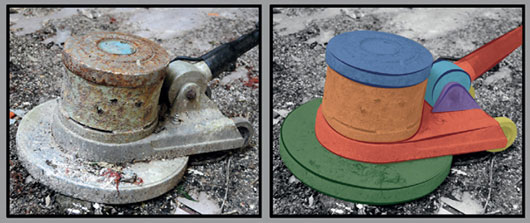
FIG 3.2
Also, the reference does not give us all the details. There are two different floor buffers with only a few shots of each. I’ll be taking elements from both buffers to create one final design.
In this situation, you could fill in the blanks yourself for missing details with concept art or as I have done for this model with extra research found online to assist me in figuring out a design.
We will start off with a quick blockout to work out any design concerns which will help us to settle on a final shape. We will then build around this blockout to create the final model.
This stage of the process shouldn’t take too long. The idea is to quickly throw together a rough representation of the object. It is likely that the final model will differ from the blockout as it is only intended as a guide.
The rough budget I have given myself for this object is 2000 triangles for the mesh with a 512 × 512 diffuse texture and 256 × 256 specular map.
2000 triangles is a lot for an object of this size, but most of the polygons will be spent making the object as smooth as possible as it is mainly made up from cylinders.
You could expect a 2000-triangles object to be used in an FPS game. For a third-person game or a racing game, it would probably be more like 600–900 and probably less for an RTS or similar game.
Now, let’s move into 3ds Max and get started.
I start by creating a cylinder for the base. I’m not too concerned with the number of sides at this point as this is only a blockout guide.

FIG 3.3
Holding Shift, I move the cylinder up in the Z-axis to create a copy. The copy is then scaled to block out the section where the motor is contained.

FIG 3.4
The cylinder is duplicated three more times and moved into position. It’s then rotated and scaled to represent the wheels and the handle. I often change the coordinate system to local when rotating shapes like the handle as it makes objects easier to work with as the gizmo goes with the object’s position in 3D space. This can be done by selecting local from the drop down.

FIG 3.5
Next, some boxes are created, adjusted, and placed to block out the shapes around the base of the handle. I’m always referring to the reference as I add new elements to ensure the position and scale look right.

FIG 3.6
The blockout is almost complete after adding a couple of more boxes to help figure out how the wheels are attached to the base of the handle. The handles on top are also added. They are currently angled as in the reference images but I may change this later.
At this stage, I am trying to figure out design issues like this and see if these solutions will work.

FIG 3.7
A few additional details were added, most notably, the edge loop showing the division between the lid and the motor encasing. A rim was also added to the lid. The intention will be to have the lid as a separate mesh and removable, so we can see the motor beneath.
The statistics are displayed in the top left corner of the viewport. The triangle count currently sits at 924 triangles, so almost half of the intended budget.
To display these statistics, click on the plus “+” symbol in the top left corner and select Configure. This will open a new window which is displayed in Fig. 3.8. You can tick or untick the information you wish to see. I prefer to at least always have the Triangle Count and Total + Selection ticked. These statistics will be of more importance as we get to the final stages of the model. It’s always good to keep an eye on the numbers, so you don’t go too far over the intended budget.
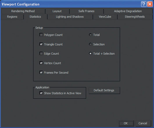
FIG 3.8

FIG 3.9
The first thing I do is to assign a different color to the blockout mesh, so it can be distinguished from the final model as this will be built over. I have assigned a standard material and changed the diffuse color. The blockout model was then placed on a layer using the layer manager. This can be accessed by clicking on the manage layers icon on the menu toolbar, and the location is displayed in Fig. 3.10.
Using layers for scene management is really useful as you can hide or freeze multiple objects with just one click. All you need to do is click on the relevant column for the particular layer in the layer manager. In Fig. 3.10, the active layer is the blockout layer as there is a check to the right of the layer name. In this state, any new meshes created in this scene will automatically go into this layer.
This is a good point to create a final mesh layer, so all new meshes will go into that instead as we do not want to be adding anything else to the blockout layer.

FIG 3.10
After freezing the blockout layer, we can start to create the final model. Frozen objects turn gray by default while they are frozen. If you wish to adjust this, go to Layer Manager and select all the objects in that layer. Then, right-click and choose Object Properties. A pop-up window will appear. Then, uncheck the Show Frozen in Gray option.
You can also access these options by selecting an object and going to Edit Menu > Object Properties > Object Properties dialog > General panel.

FIG 3.11
I then create a cylinder with 25 sides, one cap segment, and three height segments to start the model. It was then converted to an Editable Poly. The two height segments were moved and scaled to create two beveled edges around the edges of the cylinder.

FIG 3.12
The top faces were left with the cap segments with all the edges converging into one vertex. The bottom was remodeled to be more efficient as shown in Fig. 3.13.
First, select the edges highlighted in the middle shape and use the Remove option from the Edit Edges tab on the modify panel to delete the edges. In this instance, it should also remove the vertices as there are no edges left on the surface. Sometimes you may need to go into vertex mode and manually delete the vertices off edges left running across the face.
The third step is to connect up all the vertices around the edge of the face with straight lines as in the third shape on the right.
This can be done by using the Cut tool under the Edit Geometry tab to manually connect one vertex to another by left-clicking on the vertex or edge where you want to start and then clicking on where you want the cut to go. Right-click to finish.
The other method is to use the Connect option in the Edit Vertices tab also found on the modify panel. I find this cleaner as you just select two vertices (it works with more also) and then hit Connect. This will connect them with an edge.

FIG 3.13
When this section is complete, duplicate it and delete the faces on the bottom as in the left image of Fig. 3.14. Then, delete half of the remaining cylinder and perform the same optimization task as before, cutting edges across the top surface of the half cylinder. Then, position this mesh on top of the buffers pad section.
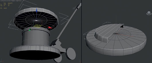
FIG 3.14
The central faces on the top surface of the pad section are now deleted as they will not be seen as we are about to build over them. The border around the hole was selected and scaled, so the edge lines up with the new half cylinder. Select the back edges of the half cylinder and extrude them backwards to roughly line up with the blockout as shown in the right image of Fig. 3.15.
The Extrude tool was used to do this. It is located under the Edit Edges tab on the modify panel. You can click on the button Extrude and control the outcome manually in the viewport, or you can select the icon to the right of this button which will bring up a small options box. You can input the settings you want into this and select the green tick to confirm. I personally set all the values to zero, confirm, and then manually adjust the edges with the Move, Rotate, and Scale tools.
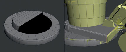
FIG 3.15
The faces at the back were created by using the Bridge tool to connect the four corner edges beforehand.
The first and failed attempt at the beveled recess consisted of using the Slice Plane tool and Cut tool to add geometry to be modified and modeled into this shape. I was not happy with the results.
At this stage, I did delete half of the mesh after using the Cut tool to create an edge running down the center of the mesh. I then applied a symmetry modifier to the remaining half so I would only have to create one of these edges.
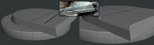
FIG 3.16
The problem was creating the curved surface leading into the beveled recess from the existing mesh. The solution was to start by creating a cylinder and deleting most of the sides. The remaining section of the cylinder would then form this curve. It is pictured in the top left image of Fig. 3.17.
The surface normals then had to be flipped so they were facing the right way. This option is found under the Edit Polygons tab. It’s called Flip. This will change the direction of selected polygons face.
The curved section needs to be combined to and worked back into the existing model as described in the following four steps which are displayed in Fig. 3.17.
Step 1 Delete the surrounding polygons in this area to accommodate the cylinder section. Then, model the curve to suit the existing mesh by moving the vertices.
Step 2 Use the Cut tool to add extra edges and vertices to the outer faces adjoining the cylinder section so it matches up. To snap the new vertices onto the curves, use the Move tool with snap turned on. To toggle snap on and off, press “S.”
Step 3 Once all the shared vertices are matched up to the curved cylinder section, combine it with the main mesh using the Attach option found under the Edit Geometry tab. Select the main shape and then attach. Next, click on the mesh you wish to combine to the main shape. When this is done, move into vertex mode and drag select around the vertices which are shared, one at a time. The statistic counter should show two vertices selected. To weld them, select the Weld option under Edit Vertices. If the weld is successful, the statistics counter should show one vertex selected. Do this to all the vertices we snapped on top of each other. It’s wise to double check all vertices in the area at this time.
Step 4 The final step consist of reducing the amount of edges in the curved section using Weld as I decided at this point there were too many. The missing side faces were replaced by extruding the top edge down and welding the vertices to close the mesh. Any remaining floating vertices or unconnected edges were fixed by using the Connect or Cut tools. The bevel running along the outer edge was also extended up along the curve in step 4 in comparison with the version in step 3 to get a nicer result.

FIG 3.17
The mesh should be missing the bottom face which hangs out over the buffer pad section. Create this by extruding the bottom edge of the back face as shown in the left image in Fig. 3.18.
When you are satisfied with the results of one half of this mesh you can collapse the stack so the symmetry modifier creates the other half of the model. To do this, right-click on the symmetry modifier in the modifier list on the modifier panel and select Collapse All. This will reduce the modifier stack back to Editable Poly.
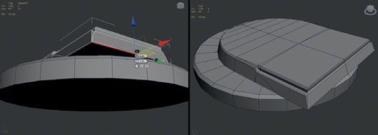
FIG 3.18
The shared vertices running down the center of the model will need to be welded using the same method as before to seal the mesh.
After welding all the vertices along the central edge, the central edge is also removed as it is no longer needed.
The motor casing and lid sections are next. These meshes can be duplicated from the blockout model to use as a starting point. The motor casing or bottom section was first to be worked on as in the left image in Fig. 3.19.
Delete the top polygon. Then, select the edge border and extrude it inwards to give thickness to the cylinder. At this stage, I did add a raised edge loop on the surface by making two separate extrusions. As I deleted it, later you can just do one extrusion.
Then, use the Extrude tool again, downwards this time to create the inner sides of the casing.
Selecting the border edge, which should now be at the base of the inner sides, use the Cap tool to fill this empty area with a polygon to create a bottom to the casing.
After this, the vertices need connecting up as before with straight lines running across the bottom surface.
You should end up with a shape similar to the version on the right in Fig. 3.19.
The only difference is I carried out a small optimization. As we do not need the inner cylinder to be as round and smooth as the outer section, I selected pairs of adjacent vertices and welded them together resulting in the final version as shown in Fig. 3.19.

FIG 3.19
The lid is next; I start on the top surface. First, delete the current top polygon and select the new border edge and extrude it inwards part way. This is to start creating the small groove visible on the top of the buffer lid in the reference photos.
Continue to extrude, move, and scale to get a result similar to the right image in Fig. 3.20. The groove consists of three edge loops in the end which together formed a V shape.
Finish the lid by capping the final border edge just before the center to create a flat poly to define the plastic area in the center of the lid top visible in the reference image.

FIG 3.20
To finish the lid, connect all the vertices around the plastic area as shown in the left image of Fig. 3.21.
Then, create the inner surfaces of the lid using the same method as before. Remember to optimize it at the end by welding the adjacent vertices. The final result is shown in the right image in Fig. 3.21.

FIG 3.21
After positioning the lid back on top of the motor casing, I moved on to the wheels. Again, I duplicated the wheels from the blockout to use as a starting point.
As before, delete the large-side polygon on the front of the wheel, and then select the border edge left behind. Extrude this once to create an angled surface to form the rim of the wheel. Then, extrude inwards again, this time all the way in to merge all the edges into one point. Then, weld this group of vertices before moving the vertex inwards to create a dipped surface for the wheel.
The back of the wheel was created in a similar fashion, except instead of going with the dipped surface, create a flat surface and make horizontal cuts across it to connect the vertices.
Next, duplicate the final wheel and rotate it 180° to make the wheel for the other side.

FIG 3.22
The next few steps required a bit of trial and error as I worked out the design for the wheel brackets and how it is connected to the box at the back of the pole. I wanted to try out a curved bracket instead of a straight one like the blockout mesh. At this point, I also created two cylinders for the wheel axles so that the brackets connect.
In Fig. 3.23, I had started by creating a cylinder. I then applied a bend modifier from the modifier list. I only used the angle setting to bend the cylinder. You may need to adjust the axis the modifier bends in depending which way your model faces in the scene.
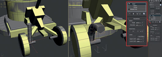
FIG 3.23
After collapsing the stack when I was happy with the bend result, the bracket was rotated and moved into place. I tried scaling it in the X-axis to reduce the roundness as I decided it did not suit the model. It was then duplicated and mirrored to create the right bracket. An extra cylinder was also created to be a bolt where the bracket and box meet. The left image in Fig. 3.24 shows the model at this stage.
I still did not like the roundness. Looking at the reference again, I preferred what was there, a flatter but bent bracket which is slightly tapered. I created a box with four height subdivisions and applied the bend modifier again to start the new shape.

FIG 3.24
Figure 3.24 shows the final version of this new bracket. I kept this version closer to the reference while being mindful of the polygon budget. To taper the bracket as it nears the axle, select the edge loops or relevant vertices in vertex mode and scale them in the correct axis to get a result similar to the center image in Fig. 3.25. In my case, it was the X-axis.

FIG 3.25
After completing the earlier section, I had a look around the model to re-evaluate the polygon distribution. In doing so, I came to the conclusion that the wheels for their size use too many polygons. I decided to remedy this now rather than later on, and I made cheaper versions using the same method as before.
The original mesh was 198 tri’s. The two new meshes were 94 tri’s and 78 tri’s. To play it safe, I went with the 78 tri option. I swapped out both wheels for the new lower resolution versions.
You may find yourself bouncing between different sections of a model a lot as you create it. I find this useful, always keeping an eye on the bigger picture and not getting sucked into small areas of detail until the end of the build. Work with broad strokes and get a consistent level of detail all around the mesh before adding really fine details.

FIG 3.26
After resolving the wheel issues, I moved on to the base of the handle, to the shapes that connect the stem, buffer, and wheel brackets. I only loosely followed the reference to create this section, since if we were to follow the reference exactly, it would be rather expensive. You can interpret this area as you like. I found a solution which I feel looks good but it is also cheap and follows the idea of the reference.
First, delete the face on the box facing the buffer that the wheel brackets are connected to. This can be seen in the left image of Fig. 3.27. We will build the new pieces over this area as intersecting geometry.
To get a result similar to the middle and right images of Fig. 3.37, create a cylinder with two height segments. The top segment is moved up slightly, and the top face was scaled in to create the beveled edge.
Next, just rotate the cylinder into position, sitting it over the face we deleted earlier.
Then, select to opposite side faces on the cylinder and extrude them outwards creating “wings.” After extruding them, I scaled the faces horizontally using the local axis, and then moved them back to create the tapered and angled “wings” on the side of the cylinder.
Two rivets created from a five-sided cylinder were placed as intersecting geometry on the front of the cylinder. All unseen geometry was deleted. Two more cylinders were used to represent the pins protruding out of the top of the “wings.” A modified cylinder was placed on one side to create a little asymmetry. In my mind, I thought this piece once held the electrical cable feeding the buffer.
Select the bottom face of the cylinder and use extrude with 0 settings. Then manually scale the new face so it sits well inside the original face. This will then be extruded down to act as a continuation of the pole and connect the cylinder to the buffer. Before extruding down, you could weld pairs of vertices together to optimize the mesh before extruding the pole segment.

FIG 3.27
As described earlier for the bottom face, use a similar technique to extrude the main pole section up from the top face of the cylinder.
Select the top face and extrude it inwards making sure the new face stays flush with the original. I adjusted the position slightly, so it was not central before extruding it upwards using the local axis to move the new extrusion. When you are happy, delete the top face of the pole as this won’t be needed.
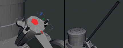
FIG 3.28
Where the pole touches the buffer I decided to put in an extra mesh to make both meshes sit better. This can be seen in the left image of Fig. 3.29a. To create this shape, start with a cylinder and delete the underside faces along with half of the remaining faces. Select the back edges facing away from the buffer and extrude them back. Use extrude again to create a back face. Then, use bridge to create a bottom face just where this shape hangs over the buffer pad.
In the right image of Fig. 3.29a, I highlighted the two rivets created from a couple of five-sided cylinders. Again, all unseen geometries such as downward facing faces have been deleted.

FIG 3.29a
Some extra attention can now be focused on the pole. To break it up, a few extrusions were added to give the impression it is telescopic/adjustable. Using the Slice Plane tool, make four slices similar to the left image in Fig. 3.29b. Then, select the faces between the inner edge loops and scale them outwards first of all, then scale them towards each other to create a beveled surface. This will help to show off the detail more.
The same process was followed for the extruded section lower down the pole. This can be seen in Fig. 3.29b and also Fig. 3.30. The only difference is that one of the faces on the side of the cylinder was extruded outwards, and then the top face of this extrusion was extruded upwards.
These new faces were then modeled to resemble the example in the image using the Weld, Scale, and Move tools.

FIG 3.29b
The handle and brakes were started from a standard box. The Slice Plane and Scale tools were used on the box to add a few edge loops, matching the shape to the reference images. Once I was happy with the shape, I used the Chamfer tool to bevel the handles and then cleaned up the extra edges using the Weld tool.
As mentioned before, feel free to do some research and create something unique if you find a more interesting design for the handle. I went for a simple more box-like form, so it would use less of the triangle/polygon budget.

FIG 3.30
As seen on the right of Fig. 3.30, the brake pedal was created from a box, which was then sliced up and modeled into shape. The Slice Plane and Scale tools were used for this.
The piece connecting the brake pedal to the box was then created using a similar modeling technique starting from a box. The only extra tools used were the Rotate and Move tools to create the slightly curved shape seen on the left of Fig. 3.31.

FIG 3.31
Next are the two bolts and some cable to connect them. This concept was loosely lifted from the reference. To start, one of the five-sided bolts created earlier was duplicated and placed on the under side of the cylinder. Select the front face of the “bolt” and delete it. Then, select the border edges and extrude them inwards.
There is no need to have the cable a five-sided mesh, so weld two vertices together to make the border edge four sided. As seen on the left example of Fig. 3.32, the shape is not quite right. So, to fix this, I created a four-sided cylinder as a guide and positioned it up against the bolts surface.
You could use the Auto Grid option located on the create panel to create the cylinder directly on the bolts surface. This can be turned on by going to the top of the object type list and ticking the box beside Auto Grid.
Then, select the four vertices defining the cables shape and snap them to the cylinders vertices, so it creates a better shape as highlighted on the right of Fig. 3.32.
Once one bolt was complete, it was duplicated and then positioned on the side of the mesh connecting the pole and buffer pad.

FIG 3.32
A curve was then created and modified to be the cable hanging down connecting the two bolts.
Go back to the first bolt, and select the internal border edges and start extruding them down. Follow the curve all the way to join up and meet with the bottom bolt. Rotate the extrusions as you go. I did have to do some remodeling of the cable at the end to get a smoother result.
Another way to do this is to use Extrude along Spline found under Edit Polygons in polygon mode as we have all the elements to do so. You will need to select the border edge and cap it first as you need a polygon to carry out this operation. I personally preferred to do this manually. Either method will require some extra modeling to clean it up.
When you are satisfied with the cable then combine this and the two bolts together and weld all the shared vertices to close up the mesh.

FIG 3.33
The motor is next. First, move the lid to the side for now. Start with creating a cylinder as shown in Fig. 3.34. Then, delete the bottom half and move it into position. Use the height segments to create curved ends on the cylinder.
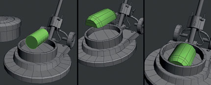
FIG 3.34
Keeping the motor simple, finish it by following the reference and building it up with boxes and cylinders.
You can leave these primitives all intersecting each other as the amount of overdraw is very small. All unseen geometry were then deleted. When I was happy with the result, I combined all the meshes using Attach and then reset the Xform of the new mesh.
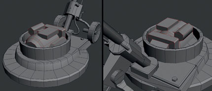
FIG 3.35
At this point, the model is pretty much complete, so all that is left before unwrapping and texturing the model is a pass on optimizing the mesh and tweaks of the smoothing groups.
The triangle count at this moment is 2300, and the polygon count is 1401. As I was aiming for 2000 triangles, some details will need to be removed. Figure 3.36 shows some of the areas where edges or details were removed. I usually get rid of excessive bevels first and then reduce the smoothness of cylinders. After that, I look at completely removing small details like rivets, if necessary. Geometry that either does not contribute to the overall silhouette or has a purpose relating to smoothing groups or unwrapping can also be removed.
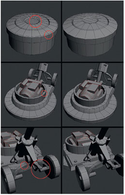
FIG 3.36
After optimizing the mesh, it ended up as 2138 triangles or 1153 polygons. This is still not the estimated budget of 2000 but it’s close enough as I’m happy with the model at this detail. It could be possible to reduce the model more to 2000 triangles if you want the challenge.
The last step I always carry out on a model is to go through the Smoothing Groups. This process ensures that I get the shading that I want across all the surfaces. I have been doing this as I went along throughout the build which is a habit I’d encourage you to pick up.
If you are not familiar with Smoothing Groups, these control the shading of the edges between faces over the surface of a mesh. I’ll use the top of the buffer lid as an example to demonstrate how they work.
The model on the left of Fig. 3.37 has only one smoothing group, so the shading is averaged across the whole of the mesh. The example on the right has multiple smoothing groups to define some of the edges better. This is extremely important when doing hard surface modeling.

FIG 3.37
The smoothing group options are only available on the modify panel under the polygon or element modes.
A good approach to applying them is to first select all the faces of a mesh and then apply smoothing group 1 by clicking on “1” from the number table pictured in Fig. 3.37. After this, select faces you wish to be shaded differently and assign group 2 to them. If you need to have two faces adjacent to each other but shaded separately from each other as well as group 1, just assign group 2 to one face and group 3 to the other.
Figure 3.38 of the lid highlights the different smoothing groups applied to the mesh. Go around the entire mesh adjusting these groups accordingly to get the desired look.
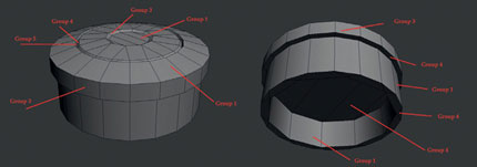
FIG 3.38
When the smoothing groups were complete, I used Attach to combine all the meshes together so they could all be unwrapped together in the UV texture editor.
Figure 3.39 shows the original blockout in comparison with the final model. As you can see, I had made a few design changes and scale modifications as I modeled the final version. This is very common when creating assets for games.
Never be too precious about your work and always be willing to improve and change it as you go. The blockout served its purpose as a quick initial first step, but it was only a rough guide.

FIG 3.39
Unwrapping and Texturing the Floor Buffer
Before even starting the unwrapping and texturing process, I first put together an image showing what type of textures I’d like to have on the model, and where they would be placed.
I find this useful as it helps me to keep a clear picture of where I want to take the model. The texture samples were taken from various sources including personal photos and online texture libraries.
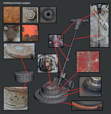
FIG 3.40
Now it’s time to look at unwrapping the model.
The first step is to apply an Unwrap UVW modifier from the modifier list. At this stage, we need to figure out the object’s size and make a decision on the texture size—whether it should be a 512 × 512, 1024 × 1024, or 2048 × 2048 texture map.
As I have already started the scene that this object is designed for, I can import some reference meshes to compare it against. The general rule for the scene is that a 5 m2 will use a 1024 × 1024 texture.
Figure 3.41 shows the pavement mesh I have imported and the original buffer on the left. I ended up scaling the buffer by 17% in the end.
I decided that a 512 × 512 texture would be sufficient for the buffer model as the pavement was using a 1024 × 1024 texture. The buffer’s texture will in fact be a slightly higher resolution than other elements in the scene. I decided that being a prop I’ll allow it to go over a little. It can always be reduced to a 256 × 256 later if it looks out of place within the environment.

FIG 3.41
With all these questions answered, we are ready to look at the process of unwrapping the model and creating the texture in Photoshop.
To start the unwrapping process, I created a custom UV map template. This is used to initially unwrap the model using the checker pattern to ensure the various UV shells get a consistent amount of space on the texture sheet. The different color quadrants are useful to know where each UV shell sits within the 0–1 range in UV space. Figure 3.42 shows the UV template which is in the project files and the lid unwrapped using it.
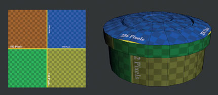
FIG 3.42
The actual process of unwrapping this model was quite simple as I only used the planar mapping, box mapping, and cylindrical mapping options available with the Unwrap UVW modifier.
Some tweaking had to be done to the UV shells/clusters using the Move, Rotate, and Scale tools in the Edit UVWs window.
The intention at this stage is to work out the layout of the texture and unwrap the most visible sections that require a different texture. Which sections to choose and what textures to apply have already been decided in Fig. 3.40.
I knew a strip of metal would be needed for the sides of the lid, so I started here using cylindrical mapping and then also planar mapped the lid top. Figure 3.43 shows these UV shells moved to one side. Each section was scaled to get a consistent resolution similar to the lid shown in Fig. 3.42.

FIG 3.43
I am trying to group all horizontally tiling strips for the bottom half of the texture sheet. The next obvious choice is the orange plastic rim highlighted to go around the buffers pad section. The UVs were placed above the metal strip of the lid. The buffers pad was also planar mapped. It was scaled to a small size as it will rarely be seen it does not require as much texture space as other elements.

FIG 3.44
Continuing to use the unwrapping, tools, the rest of the buffers pad was unwrapped and also the interior sections of the lid and casing. These areas will be either covered by other meshes or rarely seen, so were given half the texture space than they would normally get. In Fig. 3.45, you can see that the casing interior’s checkered pattern is larger than the outer faces.
The wheels were unwrapped next using a planar mapping for the sides and back and cylindrical mapping for the rim and tyre.

FIG 3.45
Figure 3.46 shows the UV layout at this stage. All unwrapped UVs have been moved outside of the 0–1 range. I then placed the strips running along the bottom half of the texture (the green and yellow quadrants). Some uniquely unwrapped assets like the lid top and wheel’s elements were placed in the blue quadrant.
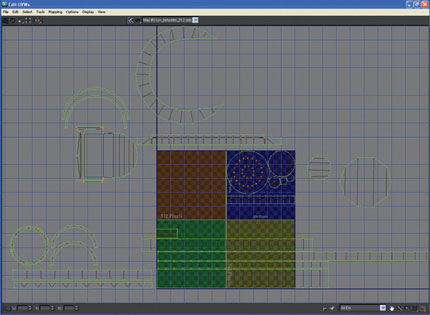
FIG 3.46
You may notice that the interior faces of the casing and the UV shells for the black plastic areas are outside of the 0–1 range. The interior pieces will just use whatever texture elements are on the sheet so I’m not including them as unique elements. Looking at the texture sheet, I have decided that the black plastic on the pad section will use a 256 × 256 tiling texture as this will work more efficiently for this section.
The unwrapping of the pole and handle section was next. These elements were placed in the orange quadrant. The UV layout of the blue quadrant in Fig. 3.47 has already been modified. Until all the shapes are mapped, I tend to constantly modify the layout.
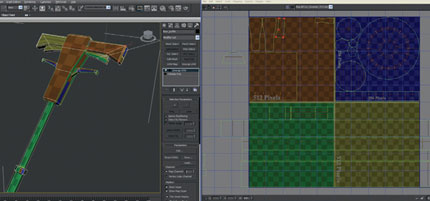
FIG 3.47
At this stage, I felt I had enough information to begin texturing. Figure 3.48 shows the final texture with the texture layout highlighted. If you compare this with the layout in Fig. 3.47, you can see how the texture sticks closely to this layout.

FIG 3.48
To get a render of the UV layout that we can bring into Photoshop, go to the menu along the top of the Edit UVWs window and select, Tools > Render UVW Template. This will open a pop-up window that will contain the settings to save this image out.
I set the size to 512 × 512. To save the file out, click on Render UVW Template at the bottom. This will save it out as a specified image file.
This image file seen on the left of Fig. 3.50 was brought into Photoshop and set to lighten over a flat gray background. This is then saved and forms the basis of our texture map.
I find texturing is a very subjective part of the 3D process. Each artist has their own opinions on what works best. The rest of the tutorial shows how I would typically do this. At any stage feel free to try your own things. Remember you’ll learn more by experimenting than following these tutorials to the letter.
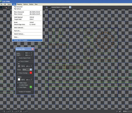
FIG 3.49
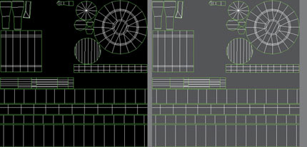
FIG 3.50
Using the UV layout as a guide, paint flat color with the standard brush onto the map. Use different colors to define the various materials in the texture. I choose to paint orange for the rubber strip, black for the handle, different shades of gray for metals, and brown for rust. The result can be seen on the left image of Fig. 3.51.
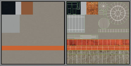
FIG 3.51
The next step is to start bringing in sections of the photo and texture reference to create the first pass of the diffuse map. This can be seen in the right Fig. 3.51.

FIG 3.52
Figure 3.52 shows Photoshop’s workspace. The toolbox is highlighted on the left. This is where you will find the Brush and Crop tools. On the right is the layers panel. This is where all these images will appear once brought into the file. The blend modes dropbox is a list of different blend modes which change how the selected layer affects the layers beneath it. We’ll be using these various blend modes a lot.
Figure 3.53 shows a slightly later version of the texture with all the different elements in place. To bring the image sections into the texture file, open the source image. Then, use the Crop tool to define the section you want to use by dragging around this area. Then, click on the Crop tool again to bring up the option to crop the image and select it. This will leave you with only the section you defined.
Then, using the Move tool drag and drop this into the texture file. You may need to adjust the order of the layers and use the Move tool to position the image section into the right place.
Most of the layers at this stage are using the blend mode normal. The only one that is not is the noise/grunge over the orange rubber strip. This is a gray scale image set to overlay, so it picks up the color beneath it. You can open the texture wip file floor_buffer_tex_05.psd to see the order of the layers and blend modes used in Fig. 3.53.
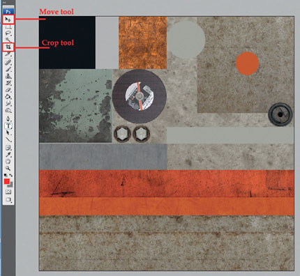
FIG 3.53
Figure 3.54 deals with the buffer lid top. A different rusted metal image was placed above the metal shown in the left image. The new image is very similar but has larger patches of rust. I used a layer mask to blend the two images together. This is a technique I use very often when I want to have two textures uniquely blended together such as metal and rust or mud and grass.

FIG 3.54
To create a layer mask on the new metal images layer, select the Add layer mask button at the bottom of the layers tab. It’s highlighted in Fig. 3.55.
This will add a thumbnail to the right of the layer’s default thumbnail. A Layer mask is a gray scale image that works like an alpha map. Areas you paint white will be visible, and areas you paint black will be invisible. All gray values in between will have the relevant amount of transparency. I usually start with flooding the mask black and then manually paint white with a brush at a medium to high opacity building up the new layer over the original gradually. The final result can be seen on the right of Fig. 3.54.

FIG 3.55
Next, I wanted to create a build up of dirt in the circular groove on top of the lid. The UV template was used as a guide. Select the Elliptical Marquee Tool and draw a circle precisely over the grooves UVs.
When you are happy that the Marquee tool sits right on top of the correct area, go to Menu > Edit > Stroke. The stroke options window will appear. Stroking the Marquee tool will draw a line of pixels that follow the marquee shape. The color, blend mode, and thickness of the line can be set in the stroke options.
To finalize the action, click on “ok.” I used a dark gray color for the line, and then set the blend mode to overlay so it will darken the texture beneath it but still allow some details below to come through.
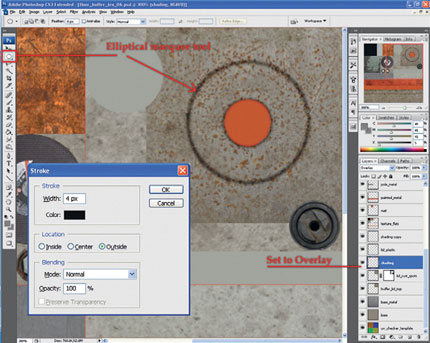
FIG 3.56
Using the layer mask technique again, additional rust was then painted on the lid and also along the metal strip running along the bottom of the texture.
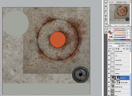
FIG 3.57

FIG 3.58
This technique was also over the orange rubber strip, used but with a dirt texture. A thin metal trim was also added over the metal strip as seen in Fig.3.58. A layer style called Drop Shadow was applied to the metal trim to create a sense of lighting and depth in the texture. You can assign this by going to the Menu > Layer > Layer Style > Drop Shadow. Then just play with the settings until you are happy with the result.
You can always go back to the settings later if you don’t flatten the image by double clicking on Drop Shadow which will appear on the bottom of the layer in the layers panel.
At this stage, if I felt the texture had enough detail I could go back and apply it to the model and continue with the unwrapping process. Before moving back to 3ds Max, a small 256 × 256 tiling texture needs to be created for the black plastic areas of the model. This is a simple texture to create consisting of three layers.
The base layer is a flat dark gray color. Use the paint bucket tool to fill the background layer with a color.
The middle layer was extracted from a photo of metal and desaturated (Shift + Ctrl + U). The blend mode is set to overlay at 59% opacity. The purpose of this layer is to add some noise and color variation to the flat gray layer.
The final layer was taken from a photo of concrete and also desaturated. The blend mode was set to soft light at 51% opacity.
The final task is to make sure this texture can tile in the U- and V-axes. When you are happy with how the texture looks, flatten the image.
To tile a texture in Photoshop, use the Offset tool found on the Main Menu > Filter > Other > Offset. This will bring up a window with options to offset the selected layer or image horizontally or vertically. As this is a 256 × 256 texture, it’s best to offset it in both axes by 128 pixels. This will make sure the texture edges end up in the center of the screen. Sometimes seams can be harsh and very noticeable.
To paint out the seams, pick the Clone Stamp tool from the toolbox. Then, define an area of the texture to clone that’s away from the seams by holding ALT and left-clicking in the selected area. Now, when you start painting over the seam you will clone the earlier selected area where you paint.
When the two seams are finally gone, apply the same amount of offset using the offset filter to return the texture to its normal position, this time without seams. Now, it is ready to be saved out and tiled over the plastic areas of the floor buffer.

FIG 3.59
Moving back to 3ds Max, open up the Material Editor (M).
As the floor buffer will need two different textures assigned to the model, we’ll need to use a multi/sub-object material.
Select a blank material and click on the Standard button (Fig. 3.60). From the Material Map Browser, select Multi/Sub-Object to change the material type from being a standard material to a multi/sub-object material instead.
The left side of Fig. 3.61 shows the default multi/sub-object material which contains 10 slots for submaterials. As we only need two, delete the excess slots and rename the two remaining slots accordingly. You should end up with a shade similar to the right of Fig. 3.61.

FIG 3.60
Submaterials are in fact standard materials except there can be lots of them assigned to a single model. Which material is assigned to which face is determined by each polygons material ID number, which we covered whilst mapping the box earlier in the book. As there are only two submaterials, this model only needs two material ID’s. The primary ID is the main buffer texture. The secondary is the tiling plastic texture.

FIG 3.61
We need to collapse the stack of the model and go back into polygon mode, and then select all the faces and set the material ID to 1.
Next, select only the faces that will use the plastic texture and set the material ID to 2. Then, assign the shader to the model if you have not already done so. You should have a similar result to Fig. 3.62.
When this is complete, we can reapply an unwrap UVW modifier and continue to unwrap the model.

FIG 3.62
After spending more time in unwrapping the model and getting a feel for how I want to continue with the texture, I moved back into Photoshop. I tend to bounce in between texturing and unwrapping a lot as I prefer to see both tasks progressing together. You could easily stay with the unwrapping process and completely finish it as there is enough information in the texture.

FIG 3.63
Looking back over the texture reference, I decided to add rust patches to the red metal and the pole. One of the rivets below the buffer pad was placed over a section of rust then desaturated and set to overlay. Work on the motor texture has started by taking part of the reference image and placing it using the UV template as a guide.
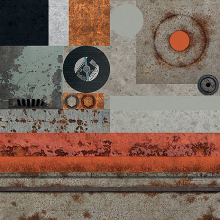
FIG 3.64
Figure 3.65 shows the results of a technique I use when creating diffuse textures. The top example in the image is a painted, rusted metal layer masked out over the red metal texture. On its own, I think it looks ok but it’s a little flat if there is no intention to use a normal map. As a general rule, it’s not advisable to have any sort of lighting in a diffuse map, but in the second image, I have used the nvidia normal map plug-in to create some subtle ambient lighting to make the flaking away paint “pop.”
I personally prefer this look over the top image.
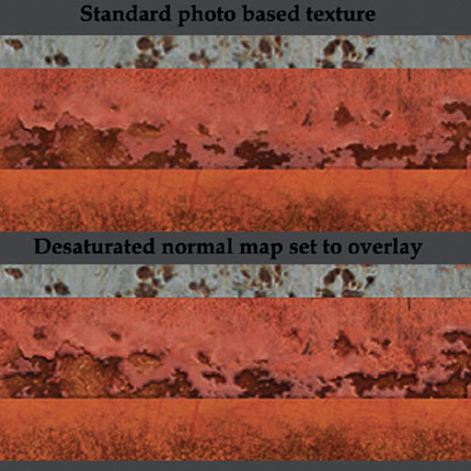
FIG 3.65
In Fig. 3.66, we go through the steps to create this effect. I tend to use it mainly for surfaces that have different layers or details such as rivets or grooves.
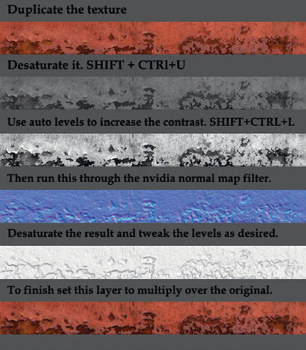
FIG 3.66
In Fig. 3.67, we show some more progression on the texture map. Various metal and mechanical elements were taken from photos I found online and used to give the motor some detail similar to the reference. Each element had to have the hue and saturation tweaked to make them sit together better.
More sections of metal images were imported and placed over the wheels tyre and surface and then set to overlay. The levels were manually tweaked to create a bit of contrast.
A new layer was created over the orange rubber layer. Using the standard brush tool and using the UV template as a guide, a white highlight was painted along the edge to pick it out on the model. This layer was then set to soft light, duplicated, sharpened and both layers had the opacity reduced until the result looked natural.

FIG 3.67
Jumping back into 3ds Max, a little more unwrapping was done to see how the new texture elements were working. Luckily no major changes needed to be made. If you take a look at the Edit UVWs window in Fig. 3.68, I have placed many of the UV shells outside of the main 0–1 range square. This is ok to do as I will not be baking any textures, and it helps to keep the workspace clean and easy to manage instead of having all the UV shells piled on top of one another.

FIG 3.68
The last steps in adding polish to the texture included changing the buffer pad texture, as I found a better example online. A label and rivets have also been added to the handle in the top left corner of the texture.
At this point, once you are happy with the texture, it is advisable to flatten the image and save it as a different file. Once this is done, use the offset filter to offset the texture horizontally by 50% its width in pixels.
This is just to give the texture one final check to ensure all the U tiling strips at the bottom of the image do not have any seams. If there are any noticeable scenes, use the Clone Stamp tool to sample other areas of the texture and paint over the seam. Once it is seamless, use the offset filter to return the texture back to its original position.
To create the specular map, save the diffuse .PSD as a new specular .PSD file. Then, create new hue/saturation and levels adjustment layers. Reduce the saturation with the hue/saturation layer to 0 to desaturate all the layers at once. The levels layer can be used to adjust the overall lightness and contrast of the image, but before tweaking this, we need to use brighten and contrast on each individual layer to separate what will be shiny and what will be matte. Darker areas of the image will have no specularity, and the lighter values will have a relevant level of shininess.
Figure 3.69 shows the final textures. We should have a 512 × 512 diffuse for the floor buffer with a complimentary specular map to match.
The other two textures are the 256 × 256 diffuse black plastic texture with a 128 × 128 specular map.
I have halved the specular map for an optimization as it’s just to add a little noise and interest to the material. If the floor buffers specular map is halved (which it could be), the contrast in shiny and matte surfaces would not be as sharp.
Once all the textures are final, you may need to go back into the Material Editor and tweak the specular level and glossiness to get the most use out of the textures.

FIG 3.69
That’s it. The model should now be ready for preparation to be used in an environment. If it was to go into a game engine, it would need LODs and a collision shape first. We’ll be looking at lodding this mesh in Chapter 6.
Figure 3.70 is the final render to display the asset in all its glory on a dirty floor.
Presenting your work well is as important as creating it, so it’s always worth going that extra mile to show off your work.

FIG 3.70

FIG 3.71