
Appendix A
dB or Not dB
In the studio, you need to know how to set and measure signal levels and match equipment levels. You also need to evaluate microphones by their sensitivity specs. To learn these skills, you must understand the decibel, the unit of measurement of audio level.
DEFINITIONS
In a recording studio, level originally meant power, and amplitude referred to voltage. Nowadays, many audio people also define “level” in terms of voltage or sound pressure, even though this terminology is not strictly correct. You should know both definitions in order to communicate.
Audio level is measured in decibels (dB). One dB is the smallest change in level that most people can hear—the just-noticeable difference. Actually, the just-noticeable difference varies from 0.1 dB to about 5 dB, depending on bandwidth, frequency, program material, and the individual. But 1 dB is generally accepted as the smallest change in level that most people can detect. A 6- to 10-dB increase in level is considered by most listeners to be “twice as loud.” Sound pressure level, signal level, and change in signal level all are measured in dB. Play audio clip 42 at www.taylorandfrancis.com/cw/bartlett-9780240821535/ to hear the effects of various decibel changes on loudness. Audio clip 43 wraps up the demonstration.
SOUND PRESSURE LEVEL
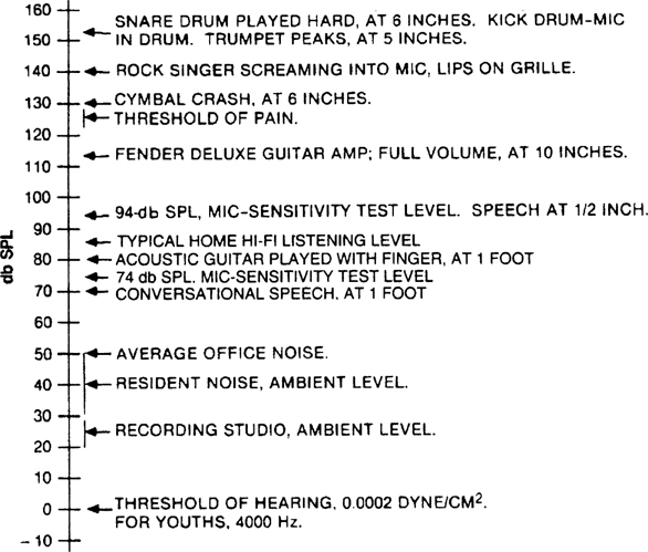
Sound pressure level (SPL) is the pressure of sound vibration measured at a point. It’s usually measured with a sound level meter in dBSPL (decibels of sound pressure level).
The higher the sound pressure level, the louder the sound (Figure A.1). The quietest sound you can hear, the threshold of hearing, is 0 dBSPL. Average conversation at 1 foot is 70 dB SPL. Average home-stereo listening level is around 85 dBSPL. The threshold of pain—so loud that the ears hurt and can be damaged—is 125 to 130 dBSPL.
FIGURE A.1 A chart of sound pressure levels.
Sound pressure level in decibels is 20 times the logarithm of the ratio of two sound pressures:
where P is the measured sound pressure in dynes/cm2, and Pref is a reference sound pressure: 0.0002 dyne/cm2 (the threshold of hearing).
SIGNAL LEVEL
Signal level also is measured in dB. The level in decibels is 10 times the logarithm of the ratio of two power levels:
where P is the measured power in watts, and Pref is a reference power in watts.
Recently it’s become common to use the decibel to refer to voltage ratios as well:
where V is the measured voltage, and Vref is a reference voltage.
This expression is mathematically equivalent to the previous one, because power equals the square of the voltage divided by the circuit resistance:
The resistance R (or impedance) in this equation is assumed to be the same for both measurements, and thus divides out.
Signal level in decibels can be expressed in various ways, using various units of measurement:
• dBm: decibels referenced to 1 milliwatt, with no defined load impedance
• dBu: decibels referenced to 0.775 volt
• dBv: decibels referenced to 0.7746 volt
• dBV: decibels referenced to 1 volt
dBm
If you’re measuring signal power, the decibel unit to use is dBm, expressed in the equation
where P is the measured power, and Pref is the reference power (1 milliwatt).
For an example of signal power, use the following equation to convert 0.01 watt to
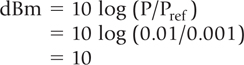
So, 0.01 watt is 10 dBm (10 decibels above 1 milliwatt).
Now convert 0.001 watt (1 milliwatt) into dBm:
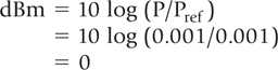
So, 0 dBm = 1 milliwatt. This has a bearing on voltage measurement as well. Any voltage across any resistance that results in 1 milliwatt is 0 dBm. This relationship can be expressed in the equation
where V is the voltage in volts, and R is the circuit resistance in ohms.
For example, 0.7746 volt across 600 ohms is 0 dBm. One volt across 1000 ohms is 0 dBm. Each results in 1 milliwatt.
Some voltmeters are calibrated in dBm. The meter reading in dBm is accurate only when you’re measuring across 600 ohms. For an accurate dBm measurement, measure the voltage and circuit resistance, then calculate with the following equation:
dBu
Another unit of measurement expressing the relationship of decibels to voltage is dBu. This means decibels referenced to 0.775 volt:
where Vref is 0.775 volt.
dBv
The unit dBv with a small “v” means decibels referenced to 0.7746 volt. This figure comes from 0 dBm, which equals 0.7746 volt across 600 ohms (600 ohms used to be a standard impedance for audio connections):
where Vref is 0.7746 volt.
dBV
Signal level also is measured in dBV (with a capital V), or decibels referenced to 1 volt:
where Vref is 1 volt. For example, use the following equation to convert 1 millivolt (0.001 volt) to dBV:
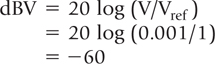
So, 1 millivolt = −60 dBV (60 decibels below 1 volt). Now convert 1 volt to dBV:
So, 1 volt = 0 dBV.
To convert dBV to voltage, use the formula
Change in Signal Level
Decibels also are used to measure the change in power or voltage across a fixed resistance. The formula is
or
where P1 is the new power level, P2 is the old power level, V1 is the new voltage level, and V2 is the old voltage level.
For example, if the voltage across a resistor is 0.01 volt, and it changes to 1 volt, the change in dB is

Doubling the power results in an increase of 3 dB; doubling the voltage results in an increase of 6 dB.
THE VU METER, ZERO VU, AND PEAK INDICATORS
A VU meter is a voltmeter of specified transient response, calibrated in volume units or VU. It shows approximately the relative volume or loudness of the measured audio signal. VU meters are used on analog tape recorders, broadcast consoles, some live-sound mixing consoles, and older recording consoles.
The VU-meter scale is divided into volume units, which are not necessarily the same as dB. The volume unit corresponds to the decibel only when measuring a steady sinewave tone. In other words, a change of 1 VU is the same as a change of 1 dB only when a steady tone is applied.
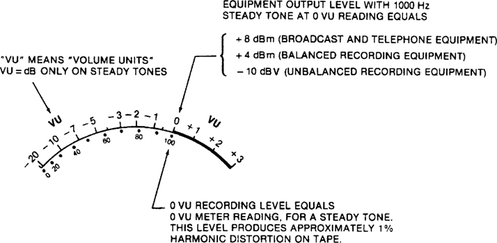
Most recording engineers use 0 VU to define a convenient “zero reference level” on the VU meter. When the meter on your mixer or recorder reads “0” on a steady tone, your equipment is producing a certain level at its output. Different types of equipment produce different levels when the meter reads 0 (Figure A.2). Zero VU corresponds to:
• +8 dBm in older broadcast and telephone equipment
• +4 dBm in balanced recording equipment
• −10 dBV in unbalanced recording equipment
• −20 dBFS on a peak-reading meter in a digital recorder or recording software
FIGURE A.2 VU-meter scale.
A 0 VU recording level (0 on the record level meter) is the normal operating level of an analog tape recorder; it produces the desired recorded flux on tape. A “0 VU recording level” does not mean a “0 VU signal level.”
With a VU meter, 0 VU corresponds to a recording level 8 dB below the level that produces 3% third-harmonic distortion on tape at 400 Hz. Distortion at 0 VU typically is below 1%.
The response of a VU meter is not fast enough to track rapid transients accurately. In addition, when a complex waveform is applied to a VU meter, the meter reads less than the peak voltage of the waveform. (This means you must allow for undisplayed peaks above 0 VU that use up headroom.)
In contrast, a peak indicator responds quickly to peak program levels, making it a more accurate indicator of recording levels. One type of peak indicator is an LED that flashes on peak overloads. Another is the LED bar graph meter commonly seen on digital recorders. Yet another is the PPM (peak program meter). It is calibrated in dB, rather than VU. Unlike the VU meter reading, the PPM reading does not correlate with perceived volume.
In a digital recorder, the meter is an LED or LCD bar graph meter that reads up to 0 dBFS (FS means full scale). In a 16-bit digital recorder, 0 dBFS means all 16 bits are ON (1) at the peak of the waveform. In a 24-bit digital recorder, 0 dBFS means all 24 bits are on. The OVER indication means that the input level exceeded the voltage needed to produce 0 dBFS, and there is some short-duration clipping of the output analog waveform. Some manufacturers calibrate their meters so that 0 dBFS is less than 16 bits or 24 bits ON; this allows a little headroom.
BALANCED VERSUS UNBALANCED EQUIPMENT LEVELS
Generally, audio equipment with balanced (3-pin) connectors works at a higher nominal line level than equipment with unbalanced (phono) connectors. There’s nothing inherent in balanced or unbalanced connections that makes them operate at different levels; they’re just standardized at different levels.
These are the nominal (normal) input and output levels for the two types of equipment:
• Balanced: +4 dBu (1.23 volts)
• Unbalanced: −10 dBV (0.316 volt)
In other words, when a balanced-output recorder reads 0 VU on its meter with a steady tone, it is producing 1.23 volts at its output connector. This voltage is called +4 dBu when referenced to 1 milliwatt. When an unbalanced-output recorder reads 0 on its meter with a steady tone, it is usually producing 0.316 volt at its output connector. This voltage is called −10 dBV when referenced to 1 volt.
INTERFACING BALANCED AND UNBALANCED EQUIPMENT
There’s a difference of 11.8 dB between +4 dBu and −10 dBV. To find this, convert both levels to voltages:
So, +4 dBu is 11.8 dB higher in voltage than −10 dBV (assuming the resistances are the same).
A cable carrying a nominal +4 dBu signal has a signal-to-noise ratio (S/N) 11.8 dB better than the same cable carrying a −10 dBV signal. This is an advantage in environments with strong radio-frequency or hum fields, such as in a computer. But in most studios with short cables, the difference is negligible.
Connecting a +4 dBu output to a −10 dBV input might cause distortion if the signal peaks of the +4 equipment exceed the headroom of the −10 equipment. If this happens, use a pad to attenuate the level 12 dB (Figure A.3, top). The wiring shown converts from balanced to unbalanced as well as reducing the level 12 dB. If you hear hum with this connection, add an isolation transformer as shown in Figure A.3, bottom. All the leads should be twisted.
FIGURE A.3 Top: Wiring balanced out to unbalanced in. The resistors form a 12 dB pad to match the balanced +4 dBu output to the unbalanced −10 dBV input. Bottom: Same, with an isolation transformer added to reduce hum.
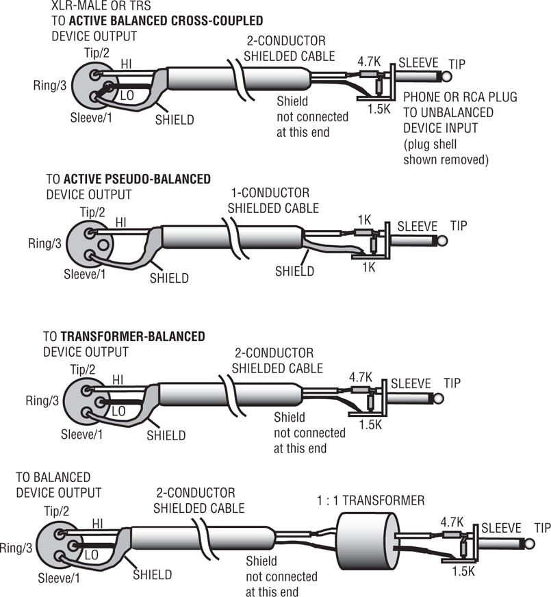
You don’t always need that pad. Many pieces of equipment have a +4/−10 level switch. Set the switch to the nominal level of the connected equipment. If there is no such switch on either device, connect between them a +4/−10 converter box such as the Ebtech Line Level Shifter (www.ebtechaudio.com/llsdes.html) or use the wiring shown here.
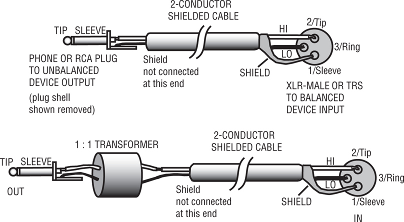
To connect an unbalanced −10 dBV output to a balanced +4 dBu input, use the wiring shown in Figure A.4. All the exposed leads should be twisted.
FIGURE A.4 Top: Wiring unbalanced out to balanced in. Bottom: Same, with an isolation transformer added to reduce hum.
MICROPHONE SENSITIVITY
Decibels are an important concern in another area: microphone sensitivity. A highsensitivity mic puts out a stronger signal (higher voltage) than a low-sensitivity mic when both are exposed to the same sound pressure level.
A microphone-sensitivity specification tells how much output (in volts) a microphone produces for a certain input (in SPL). The standard is millivolts per pascal, where one pascal (Pa) is 94 dBSPL.
A typical “open-circuit sensitivity” spec is 5.5 mV/Pa for a condenser mic and 1.8 mV/Pa for a dynamic mic. “Open-circuit” means that the mic is unloaded (not connected to a load, or connected to a mic preamp with a very high input impedance). If the spec is 5.5 mV/Pa, that means the mic produces 5.5 mV when the SPL at the mic is 94 dBSPL.
If you put a microphone in a 20 dB louder sound field, it produces 20 dB more signal voltage. For example, if 74 dBSPL in gives 0.18 mV out (−75 dBV), then 94 dB SPL in gives 1.8 mV out (−55 dBV); 150 dBSPL in gives 1.1 volt out (+1 dBV), which is approximately line level! That’s why you need so much input padding when you record a kick drum or other loud source.