Rotogravure Printing
This chapter describes the rotogravure printing process. The process involves transferring ink, one color at a time, from a cylinder in which a pattern of cells has been engraved to a substrate. Additional colors, each registered to the locations of those printing previously, are added. This multicolored pattern of inks dots on the substrate takes on photographic quality with the halftone printing effect. Dot patterns can combine to appear to the eye to be colors not present in the applied ink. Ink metering involves a doctor blade assembly that wipes excess ink amounts from the cylinder surface to provide careful control of the volume of ink transferred from each cell.
Keywords
Color register; continuous tone; cycle time; doctor blade; gravure cylinder; gravure ink metering; gravure process; halftone image reproduction; image screening; primary colors; secondary colors
At present, most flexible packaging is printed using either the rotogravure or the flexographic (Chapter 3) printing method. Rotogravure (or simply, gravure) is the more mature package printing process. It enjoys widespread use around the world. Basic gravure process technology is also used for magazines and other publications, catalogs, newspaper supplements, labels, cartons, gift wrap, wall/floor coverings, and a variety of precision coating applications (see Chapter 4).
Gravure printing for packaging provided the ability to reproduce detailed text information in small font sizes as well as excellent photographic-like reproduction of products, serving suggestions. The process gained widespread appeal for opaque flexible packaging (especially materials incorporating paper and aluminum foil). Its durable metal printing media were well suited for large production runs (500,000 impressions and more). The time and expense to produce or modify these media also favored stable package graphics with infrequent changes.
Greater market segmentation (i.e., smaller target market sizes) and changeable product messaging for global consumer product goods have stimulated significant recent innovation in gravure press equipment. The innovation has done much to lower the economic order size for gravure-printed packages.
Gravure Process
Gravure printing requires a cylinder engraved with hollow “cells” (precisely shaped depressions in the cylinder’s surface) on the order of 0.001–0.002 inch (0.025–0.05 mm) in diameter. Cells’ distribution and volume determines the lightness/darkness of particular image area. The printing equipment fills the cylinder’s cells with ink. Ink transfers to the substrate in a pattern matching the cell pattern as the cylinder presses against (i.e., “nips”) the substrate (Figure 2.1).
Gravure Cylinders
Because the cylinder directly contacts both ink supply and printed substrate, storing, handling, and using them require extreme care. Traditional cylinders have a steel core with a layer of copper electroplated on it. The cells for carrying ink are engraved into this relatively soft copper layer and a layer of protective chrome electroplated over the entire surface.
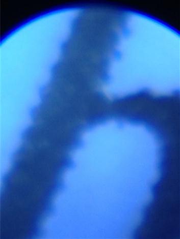
The printed image consists of hexagonal-shaped (or similar) cells that are engraved into the copper cylinder using a computer-driven engraving head with diamond tip (electromechanical method). The former “chemical etching” process is rarely used now. In it, the cylinder is covered with a gelatin photo-resist (a water-sensitive, fibrous paper, coated with a smooth gelatin layer, which has been sensitized to light by submerging it in a bath of potassium bichromate and water). The cylinder is then exposed to UV light to harden the gelatin resist. Finally corrosive ferric chloride solutions of varying strengths etch printing cells into the copper layer of the cylinder where it is not protected by the hardened gelatin. These two traditional engraving methods leave distinct semicircular (scalloped) edges on lines (Figure 2.2). Recently, direct laser engraving into metallic cylinders with high reproducibility and pulse energy stability is possible with high power laser systems. The method can vary the diameter, depth, aspect ratio, and shape of each cell independently using digital image data [1]. Engraving thin-walled metallic sleeves that slide over reusable press cylinders represents the latest cylinder preparation technology.
Halftone Image Reproduction
This discussion on halftone image reproduction applies to all printing processes. Its introduction in this rotogravure chapter reflects the history that the gravure process itself utilized the concept for mass production of “photographic quality” images for packaging and many other products well before other roll-to-roll techniques. The requirements for halftone printing presented here provided an ideal match to gravure’s cell-by-cell application of ink to substrates.
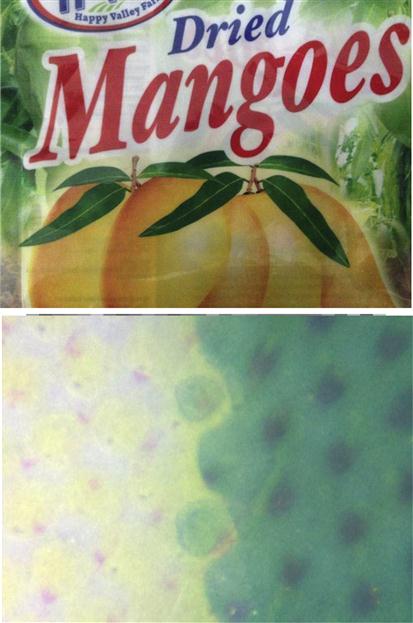
Reproducing photographic-like images presents all printing processes with a crucial test: producing a continuous range of grey tones or color values from a discrete number of printed colors. Printing methods meet the challenge by tricking the eye into perceiving a pattern of discrete dots as a blended range of smooth shade transitions (Figure 2.3). At any given distance, an observer loses the ability to distinguish individual dots from one another as the size of those dots decreases. If arranged properly, the dots appear in the aggravate as a shaded continuum. Black dots on white backgrounds appear as shades of grey (Figure 2.4). Colored dots on white backgrounds appear as lighter or darker shades of that color. Printing different colored dots in close proximity appears to the eye as a wholly differently color depending on the effects of light filtering by the ink. “Properly arranging” in this sense implies dependably printing the planar location and thickness of those dots. A rigorous prepress analysis of an image by a “screening” process determines this arrangement, given the colors of ink available and the required range of tonal variation. The term reflects its historical development involving literal use of cross-line screens to subdivide the image into a regular grid of dots varying in size. In this sense, the dots are analogous to the concept of the film grain resulting from the small particles of metallic silver, or colored dye clouds, in emulsion-coated photographic film. The printed images are generically called “halftone images.”

The additive system of color involves mixing light of the three primary colors (red, green, and blue—“RGB”) in various proportions to obtain specific color values. The combination of two of the standard three additive primary colors in equal proportions produces an additive secondary color—cyan (green+blue), magenta (blue+red), or yellow (red+green) (Table 2.1). This second group of three colors (abbreviated “CMY”) comprises the standard primary colors of the subtractive color system. Only one of the primary colors (red, green, or blue) remains when one of the subtractive primary colors (cyan, magenta, or yellow) has been removed from an image (Table 2.2). Simply inserting a filter of the subtractive color to be removed between the source of light and its receptor accomplishes this. A printed layer of transparent ink serves as such a filter for halftone images.
Table 2.1
Secondary Additive Colors (=Primary Subtractive Colors)
| Additive Color | Plus Additive Color Appears | ||
| Red | – | Yellow | Magenta |
| Green | Yellow | – | Cyan |
| Blue | Magenta | Cyan | – |

Table 2.2
Primary Additive Colors from Subtractive Colors
| Subtractive Color | Minus Subtractive Color Appears |
| Cyan | Red |
| Magenta | Green |
| Yellow | Blue |
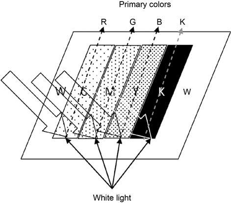
Combining halftone printing with subtractive color theory provides the ability to print “continuous-tone” images with almost photographic quality. Ambient (white) light from the environment passes through the layers of C, M, and Y colored inks, reflects from a white (e.g., paper) surface though the ink layers again giving the intended effect of the additive RGB colors and tones in between. In practice, a black (K) ink provides the image’s zero-light reflecting regions because the subtractive ability of the other three is less than complete (Figure 2.5).
The optics of Figure 2.3 demand careful control over three dimensions of the printed ink: (1) machine direction and (2) cross-direction of ink on the substrate, which define its contribution to the halftone effect, while the (3) depth of the ink layer itself (along with the ink’s “color value”—discussed in Chapter 3) determines the quality and quantity of white light filtering occurring while light travels into and back out of the ink layer. Reducing variability of these three dimensions serves as a major objective for increasing the productivity, quality, and output of rotogravure presses. Ink layer depth of course depends on the volume of liquid ink deposited from cells onto the substrate. Depending on ink and substrate, “electrostatic” pinning may be employed to create an electric potential between engraved cylinder and substrate to assure complete release of the cell’s ink volume onto the substrate. While quality of both ink and substrate affects print results, a gravure press itself has only minimal ability to adjust for variability in these raw materials.
Ink Metering
The term “meter” in printing industries generically refers to the controlled application of fluid ink to the print media that is to eventually transfers the ink to a substrate. In this sense, a fluid is a substance that continually flows under an applied “shear” stress (i.e., at least partially lateral, as distinct from compressive or tensile stresses, which act perpendicularly to a surface). An ink’s tendency to flow (from high, e.g., a “liquid” ink, to low, e.g., a “paste” ink) depends on its composition. Components include three categories:
1. Pigment1: the color itself.
2. Binder: a chemical matrix capable of adhering the ink to a substrate and holding the pigment in a three-dimensional matrix.
3. Diluent: a chemical capable of (i) causing the complete ink mixture to be sufficiently fluid during the printing process and then (ii) changing physically (e.g., evaporating) or chemically (e.g., cross-linking) so as to render the printed image a solid layer (“ink film”) on the substrate.
Additional modifiers may be added to the ink formulation to give desired functionality to either the fluid or the dried ink. Each combination of printing process, substrate, and print durability presents its own challenge in formulating an ink from components optimal for that use. The industry uses a trial and error process, guided by chemical and physical theory as well as experience to match an ink formulation to any given application. The industry has advanced to a point allowing quantitation of critical fluid ink characteristics in order to predict consistent print quality results from the printed ink.
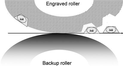
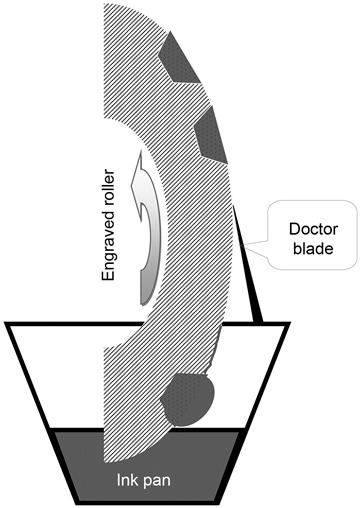
Metering ink into the cells of a gravure cylinder requires that it flows into the cells, filling them completely. Gravure inks are liquids that will flow readily in response to gravity, electrostatic forces, or capillarity. Figure 2.6 indicates how a gravure press controls the amount of ink in each engraved cell:
• The engraved roller rotates though an “ink pan” filled with one ink color.
• Liquid ink flows into each cell. A convex meniscus results over the top edges of cells because the particles in the ink have a stronger attraction to each other (cohesion) than to the material of the cell (adhesion). Ink may also adhere to un-engraved portions of the cylinder.
• Excess ink over the top edges of cells and on the un-engraved cylinder surfaces is “wiped” from the cylinder by a “doctor blade” (“doctor” here is a corruption of the German “ductor”).
• Ink wiped by the doctor blade falls back into the ink pan.
A “chambered doctor blade” assembly provides a more refined and controllable configuration of the basic ink metering as shown in Figure 2.6. The assembly isolates the ink and doctor blade from the environment, reducing the amount of ink solvent that can evaporate into the atmosphere. In a chambered doctor blade system, coating is pumped into the chamber and disbursed to the engraved roll with the help of a pair of doctor blades: the metering blade and the containment blade. The metering blade wipes the excess coating from the roll while the containment blade keeps the coating from leaking out of the chamber (Figure 2.7). End seals keep the coating from leaking out the ends of the chamber.

Gravure Process Innovation
Markets for packaged consumer goods and improved competing printing technology have taken market share from gravure in recent years. The industry has responded with major redesigns of equipment and work practices to increase affordability of the process. Gravure’s inefficiencies principally result from cylinder costs and job changeover times (see Chapters 8 and 9). Both add to the fixed costs of any given job. By decreasing either or both, the productivity and yield of gravure’s variable costs can keep the process competitive.
Cylinder Cost and Cycle Time
The cross-section of a gravure cylinder. In Figure 2.8 provides a reference for innovation efforts to lower gravure costs:

The reusable steel base has remained relatively constant in the industry.2 Traditionally, copper and chrome layers from a used set of cylinders must be removed before engraving a new set of images. However, the new direct laser engraving process is designed to image a zinc layer on the copper plating. This process allows reuse of the expensive copper plating with only zinc and chrome removed for each new job. The metal plating processes have been automated with robots and electronic controls, allowing essentially 24/7 production of cylinders with no labor costs. Electromechanical engraving, itself faster than the previous photo-resist/chemical etching sequence, is now subject to challenge to direct laser etching because of engraving speed and control of cell geometry and size. The laser technology is analogous to laser imaging technology used for photocopiers and digital “laser-jet” printing. The compatibility aids in reducing the time needed for “prepress” design, review, revision, and approval.
New thin-walled metallic sleeve engraving processes offer both cost and time advantages. Sets of base cylinders of given diameter can be in use in press while engraving sleeves for a new job requiring that diameter. This lessens the inventory cost of cylinder bases. The ability to proceed to engrave sleeves while base cylinders are in use shortens turnaround time between artwork approval and actual production.
Work Practices
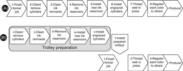
The flexible packaging converter’s “uptime” for any given value-adding line is a critical measure of productivity (Chapter 9). Historical equipment design required an essentially sequential approach to the job of changing from one print job to the next:
• Clean and remove print cylinders
• Clean press parts of previous job’s ink remnants
• Remove and/or reposition reservoirs of various ink colors.
• Install ink reservoirs and related hardware for new inks
• “Thread” new job’s substrate though press (each print station)
Figure 2.9 suggests how modern gravure press design allows converters to perform the demanding cleanup and setup of each ink station for a press. In parallel while the current job is still in press. Specialized “setup crews” work on interchangeable trolley assemblies while the press itself continues to print. A given trolley holds a print cylinder and its corresponding ink reservoir, ready to be rolled into place, as soon as the current job finishes. With trolleys in place only threading the web through the press and registering colors to one another remain before new production begins. Such arrangements reduce down-time between jobs from as much as 90 min per color station (12 h for an 8-color press) to 90 min between final good print from the previous job and initial good print on the next job.