
Chapter three
Alternative layouts
3.1
Options using existing topsoil
3.1.1
Assessment of priorities
When assessing a new site for sports turf development, or an existing facility for improvement, the designer at some point will require to know the finance available. In practice it frequently happens that the client turns the question back to the designer, requesting some idea of the costs to be associated with all the possible options. This is the point at which real discussion begins on priorities.
The first priority is to isolate the site from extraneous surface and ground-water influences by the installation of peripheral, interception drainage. Thereafter, the least sophisticated option would be:
- grade the surface to an even slope of at least 1:60 so as to allow for substantial run-off at times of intense rainfall;
- lime and encourage what drainage and structural improvements can be achieved by promoting earthworm activity;
- control use to ensure that no play is allowed when the surface is soft.
This represents the minimum likely to be reasonably effective for general use on a natural site with a satisfactory soil profile. Unfortunately, in the majority of situations in Britain the natural soil is unlikely to provide drainage to a standard sufficient to sustain a full programme of winter use, unaided.
If it is the intention to provide facilities for a high standard of play, then early consideration may have to be given to the desirability of modifying the existing slope, recognizing that the soil disturbance involved will make sophisticated supplementary drainage inevitable. If the area is large enough for several pitches, major grading into terraces may be necessary and this will in turn affect the layout of any general system of drainage installed.
3.1.2
Technical considerations
Herringbone and grid systems of pipe underdrains
A herringbone system of pipe drainage involves a series of laterals linking into a main drain, alternately from either side. The main in the middle runs directly down slope; the laterals cross the slope diagonally.
A grid system consists of laterals, arranged in parallel succession, generally crossing the slope diagonally (Figure 3.1), discharging into a main drain on one side only, usually off the pitch or along the site boundary.
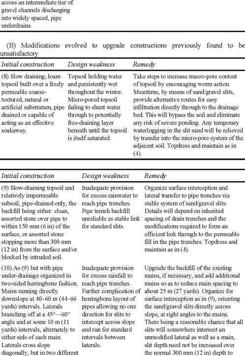
A grid system of drainage can be upgraded without difficulty by the addition of slit or mole drainage, either system being uniformly oriented at right angles to the laterals. In a herringbone system, because laterals come in from opposing
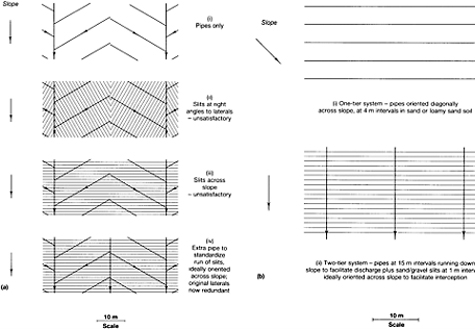
FIGURE 3.1 (a) The problem of superimposing a slit system on a herringbone layout of pipe underdrains. (b) Pipe layouts generally more suitable for sport.
diagonals, this makes it impossible for slits or moles to be effectively orientated across the laterals without the direction having to be changed whenever a main is crossed. Orientation at right angles to the mains leads to the problem of variable slit length. This dilemma is illustrated in Figure 3.1.
Situations where a standard or slightly modified herringbone system is likely to be preferred are as follows.
- Situations where the sand content of the soil is sufficient to provide a degree of natural drainage through the bulk of the soil, obviating any need for augmentation by slits.
- A site where opposing slopes meet, to form a shallow valley, leaving the main to follow the lowest contour.
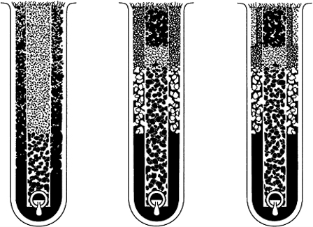
Soil depth
In all cases the minimum depth of easily trenchable soil for the installation of pipe-drain laterals should not be less than 450 mm (18 in) and, ideally, should be at least 600 mm (24 in).
If deep trenching is likely to be difficult, the problem may be overcome in one of two ways:
- inserting an intermediate system of transverse gravel channels between the surface slits and pipe underdrains to allow a marked reduction in the pipe required within the inhospitable sub-stratum—a three-tier system;
- employing perforated plastic mini-pipes at the bottom of the surface slits—a one-tier system (Chapter 2, page 42).
3.1.3
Theoretical considerations affecting the design of grid systems
Pipe and slit efficiency
- Pipes are generally laid on a gradient to direct discharge one way. Rather than attempting to impose an even gradient on the trench base, which implies an ever deepening trench with increasing cost both for excavation and backfill, it is usually best to give the pipes the benefit of any general, site slope. This allows the trench to be maintained throughout at a constant depth from the surface.
- On sports fields, slits and gravel channels are most efficient for surface interception when laid flat across slope and, as such, are free to discharge equally at either end.
- As indicated by the relationships in equations (4.4) and (4.6), pp 67–68, halving the length of run between outlets, S, or doubling the depth of the slit, H, will result in a four-fold (22) benefit to the discharge rate, i.e. the overall design rate V. Similarly, as the data in Table 7.2, page 119 indicate that hydraulic conductivity K is improved roughly three-fold for a doubling of D K (the effective particle size of the permeable fill), this is the order of benefit that will accrue to the overall design rate, V. However, a doubling of the slit width, or a halving of the interval between slits, will only increase the overall design rate two-fold.
- If slits or gravel channels are oriented downslope and flow is redirected all one way, this will have two effects.
(a) Efficiency will be reduced, by the path length to discharge point having been extended.
(b) Though the extra push given by the gradient will tend to increase the rate of flow, this effect will not produce a net benefit until the slope exceeds a gradient that would be unacceptable on most playing surfaces (see also section 4.1.2, page 66).
Which tier system of layout?
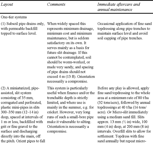
Depending on circumstances there are, broadly speaking, three grid systems of artificial drainage to choose from. These may be thought of as consisting of one, two or three tiers of artificially organized, horizontal flow and are summarized in Table 3.1.
One-tier systems
In a one-tier system the dual functions of surface interception and pipe discharge are carried out within one set of trenches, all of uniform depth, oriented in parallel succession, diagonally across the slope. The permeable backfill over the pipe, if brought through to the surface, will intercept free water moving downhill, either over the surface or through the topsoil, letting this down to the pipe for discharge. The ideal orientation for interception would be for the trench system to run directly across slope, but then the pipe would have no gradient to assist its discharge unless the expensive and cumbersome expedient were adopted of imposing a gradient on the base of each trench.
Running the trench system directly downhill, to give priority to discharge, would obviate the need for a graded fall to be artificially imposed on the trench but would adversely affect the efficiency of free water interception. The diagonal orientation is thus a logical compromise. It gives half the benefit of the slope to each of the two separate functions which, in a one-tier system, have both to be accomplished in a single trench.
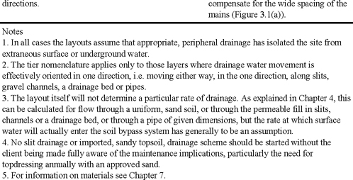
TABLE 3.1 Drainage options
(A) Summary of options for new constructions
Another system of one-tier drainage has been made possible by successful miniaturization of the much more massive, trenchless drainage equipment used by agricultural drainage contractors. It is now possible to insert continuous, corrugated, 35 mm, perforated plastic pipe, spaced at 1 m (1 yard) intervals or less, in slits 300–350 mm (12–14 in) deep. The slits should be just wide enough-40 mm (l1/2 in)—to take the pipe and should be simultaneously backfilled to the surface with a free-flowing, fine grade of trench gravel, or a grit such as SN8 in Table 7.1 However, such a narrow slit and coarse backfill is very vulnerable to capping. Measures to counteract will inevitably involve the further expense of either an efficient and continuous programme of sand topdressing, or periodic recovery by cross-hatching with a system of micro-slits.
The main advantage of the main-pipe approach is that it allows for the whole process of interception and discharge off pitch to be achieved within a total depth of 350 mm (14 in). It has the built-in disadvantages of having to intercept and discharge while oriented diagonally across the slope and requires a budget that will stretch to allow the mini-pipe trenches to be close-spaced and maintained in freely permeable contact with the surface. The long runs of small-bore pipe, the coarse backfill and the narrowness of the slits, render the system particularly vulnerable to deterioration by silting (Chapter 4, page 69).
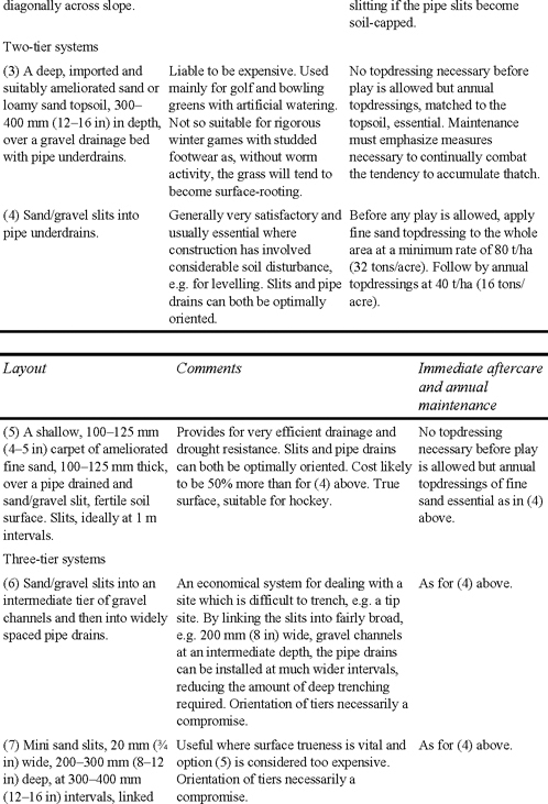
Two-tier systems
Only in a two-tier, grid system, where the two tiers cross at right-angles can we hope to achieve maximum efficiency. If the top tier consists of slit trenches, these can be oriented in parallel succession, directly across the slope, so as to intercept with maximum efficiency. The pipes, running directly down the slope, are at their best orientation for discharge and the trenches can all be installed at a uniform fixed depth from the surface. Slit length between the pipes will then be the shortest possible.
In a trenched two-tier system the relatively wide pipe trenches are not required for surface interception and so can be finished off at the surface by replacing the original turf. This eases the task of re-establishing the grass and maintaining a uniform appearance.
Because of budget constraints, or reluctance to risk prolonged loss of use, it may be necessary to phase the work, first installing the pipe drains, then following with the installation of slits sometime later. Installation of the pipe system need not be an unduly expensive operation and need not involve any loss of use if backfilling with gravel, sand and turf goes simultaneously with trench excavation and pipe laying. However, as the pipes run directly downslope this first phase will not confer much benefit on its own but, when funds and time are available to complete the job another year, the sand/gravel slits can then be rapidly installed on a stable surface, starting early in the spring. This early start will allow ample time to reestablish the sward and apply a protective topdressing of fine sand before winter use resumes.
Three-tier systems
Generally, three-tier systems arise when there are special conditions to cope with, either at the surface, or at the depth of the pipe drains. For example, when trenching and artificial grading of the pipe system is likely to be particularly difficult because of the intractable nature of the substratum, a second tier of gravel channels is introduced between the pipe underdrains and the surface slits. This allows the number of pipe underdrains required to be kept to a minimum.
In such a three-tier, intersecting, grid system it is inevitable that there will have to be compromises in efficiency unless the top tier is not a system of trenches but a substantial sand carpet. A top tier of slit trenches, oriented across the slope, would require the middle tier of intersecting gravel channels to run down the slope, and they, therefore, would discharge mainly one way. As explained later (page 66), providing the gravel channels are free to discharge either way, a slight slope on the trench will confer a small benefit on the rate of water clearance to the underdrains. The orientation with slope, however, will adversely affect their interception efficiency, except where drainage water is delivered directly to them by the top tier of sand/gravel slits. Also, as the third tier of pipe trenches would require to run across slope, any grading required for discharge would have to be achieved artificially. Alternatively, if priority is given to the third tier of pipe trenches, giving them the benefit of any natural slope, this would enable the second tier, represented here by the gravel channels, a chance to achieve their maximum efficiency for interception by being oriented directly across slope. However, the top tier of sand/gravel slits would then be at a disadvantage for their main function of free water interception, because they would have to run in parallel succession down slope. The compromise of skewing all tiers to run alternately on one-or-other diagonal would incorporate some element of inefficiency in each tier. Inherited elements of the drainage system, or constraints imposed by the site will normally dictate which alternative to choose.
Example 3.1
On many tip sites the assortment of rubble, domestic debris and blinding material forming the substratum is not only difficult to trench and of uncertain permeability, it is often covered by less than the minimum 450 mm (18 in) of easily trenchable soil normally required for pipe drain installation. It may then be advisable to plan from the start for minimum deep trenching. Thus, though we install from the bottom up, it is often useful to plan from the top down; in this case planning first for surface interception into sand/gravel slits. These can run at 1 m intervals in parallel succession across the slope, and beneath these an intermediate tier of gravel channels, 200 mm (8 in) wide, 350 mm (14 in) deep, at 4 m (13 ft) intervals, running downslope. The gravel channels will then be able to leak away into the tip blinding layer wherever they can, allowing a minimal pipe system to be installed within the rubble, at right-angles beneath the gravel channels, intrenches artificially graded to ensure discharge.
Example 3.2
Where surface trueness is vital, as for hockey, but there is insufficient money available to plan for a slit system covered by a 100–125 mm (4–5 in) deep, ameliorated sand carpet, a reasonable alternative is to plan for surface interception into a mini-slit system. For this, thin slits, 20 mm (3/4 in) wide, 200 mm (8 in) deep, filled with a medium sand (e.g. SN12 in Table 7.1) and spaced 300 mm (12 in) apart, should run in parallel succession, at right-angles across the slope. Beneath these there can be an intermediate tier of grit or fine gravel channels, and at right-angles, beneath the gravel channels, an artificially graded final tier of pipes, or a stone soakaway.
In three-tier schemes neither the trenches forming the gravel channels nor the pipe trenches need be backfilled with freely permeable material right through to the surface. They can be finished off with a soil-based turf that will rapidly marry in with the rest of the sward. This leaves only the two-part, sand/ gravel slit system, or the mini-slit system to be directly re-seeded, or to grass itself over by reinvasion from the side.
Example 3.3
A temporary, three-tier system may arise by accident when a two-tier slit system is allowed to become soil-capped through maintenance neglect. Shallow micro-slits, aligned at right angles to the original slits, are used to reestablish surface interception.
Practical considerations arising on site
- Whichever system is used, the layout should be so arranged that, as far as possible, main drains avoid the actual pitch areas. In particular, they should not pass under cricket tables.
- It is desirable that space should be available for the side-or-end-shifting of winter games pitches so that worn areas can be given a chance to recover between seasons. About 10 m (11 yards) is normally allowed for movement either way and it is essential that, where these areas are provided, they should be fully covered by the drainage system.
- To prevent displacement or penetration of pipe drains by roots, drain lines should be kept well away from trees and bushes. Where such contact is unavoidable, special precautions should be taken to prevent blockage of pipes, e.g. by using, for mains, glazed pipes with sealed joints.
3.2
Options where there is also a need for the importation of new topsoil
If the soil is very shallow, or thoroughly degraded and subsoil in character, it may be necessary to consider creating a new topsoil by importing appropriate soil-forming materials. This is a procedure that will inevitably lead to a major escalation in cost unless the materials to be imported are available at artificially low prices.
The only other alternative is to allow time for the degraded soil to be reconditioned biologically before further developing the site for sports use. This does not mean merely abandoning it to nature for a number of years as nature, unassisted, may take 50 years or more to achieve what well directed, purposeful management can achieve in 5–10 years (Stewart and Scullion, 1989).
Essentially, the aim must be to rapidly introduce an adequate and appropriate earthworm population to a mechanically opened surface, encouraging the earthworms to thrive and remain active by the prior installation of an underdrainage scheme that will allow for full drainage benefit from regular subsoiling. Maintain under grass with soil pH above 6. Avoid high concentrations of freely soluble fertilizer, and steer clear of pesticides, many of which are harmful to earthworms though not specifically targeted against them. Return all organic residues by allowing clippings to fly, or carefully grazing with sheep. An inoculum of earthworms, simply scattered onto the surface, will merely feed the birds.
A new semi-artificial surface can be formed of topsoil sand plus appropriate ameliorants. This should be laid over one of two very different systems of underdrainage:
- a slit system, bypassing excess, infiltered, surface water directly through the buried, problem layer;
- a drained gravel bed protected from infiltration of fine sand from above and soil from below by shallow layers of a blinding sand or by sheets of a synthetic fabric filter.
Choice will involve considerations of cost and the type of playing surface required.
3.2.1
Cost
The gravel-bed approach involves two or three times the amount of imported material compared with that required for the slit-based alternative. On the other hand, although slit systems require much less imported material, they require special equipment to cut and backfill the extensive system of narrow drain trenches.
3.2.2
Character
For winter games, a sward established on an ameliorated sand topsoil, and shallow enough at 100–125 mm (4–5 in) depth to ensure that the roots reach through to the water and nutrient reserves retained by the slit-drained soil beneath, will be well buffered against waterlogging, drought and hunger. Under these conditions a strong-growing grass, such as ryegrass, can dominate and form an excellent, wear-tolerant sward for rigorous games such as soccer, rugby and hockey.
However, a sward established in a deeper layer 300–400 mm (12–16 in) of topsoil sand perched over a blinded and drained gravel bed will have to be well adapted to cope with the dual threats of periodic waterlogging and periodic drought. The drought risk is an inevitable consequence of the severely limited depth of the soil layer. The waterlogging, which particularly affects the lower half of the soil, arises from the break in capillary continuity caused by the air that is locked within the gravel. In such a construction, water can be rapidly shunted through the sandy topsoil to clear the surface, but even sand cannot then complete the job of drainage through to emptying enough of the pore space to allow for satisfactory aeration. Ryegrass yellows badly under these conditions and also, being illadapted to cope with drought, gives way to the finer grasses which, though better adapted to cope with drought, are ill-adapted to cope with wear. The result is a construction that is only appropriate for the smooth, worm-free, close-cropped surfaces required for golf and bowling greens. They look well if protected from wear but they are the most demanding and expensive of all swards to construct and maintain.
Thus, to plan construction we need to know the type of use and the standard of maintenance that can be anticipated, and then, taking the character of the site into consideration, progress stepwise through the possibilities until the client finds the best match between the budget available and the standard of performance considered acceptable.