
Chapter two
Components of a drainage scheme function and installation
2.1 Field drainage
2.1.1
Peripheral, cut-off or interception drainage
It is important to ensure that the field to be drained is protected against the influx of water from surrounding land. Within-field drainage then needs to be designed to cope only with the excess rain falling onto the field itself. In some cases it may be found that a good system of perimeter drainage will obviate the need for anything more.
If there is the slightest risk of extraneous water reaching the area to be drained, either on the surface or below ground, its interception must be assured by the installation of appropriately sited drains before work on the within-field drainage system is allowed to proceed. Without this protection the drainage designer cannot specify accurately a drainage system to a given design rate.
Interceptor drains may be in the form of ‘French’ or catchment drains, or open ditches leading to outfalls capable of taking the full amount of water likely to be collected under peak conditions. Ideally, any peripheral interceptor drain should be monitored as an open trench for a year to assess the efficiency of interception and the amount of flow, before piping and backfilling.
‘French’ or catchment drains
These are often fairly wide, tapering trenches, perhaps 300–450 mm (12–18 in) at the top, filled with clean, 12–38 mm 1/2-11/2 in) stone, or 6–10 mm (1/4–3/8 in) gravel, to within 25–50 mm (1–2 in) of the ground surface. The depth is usually between 600–900 mm (2–3 ft) but may be more where there are deep underground flows requiring interception. There should be a good fall towards the outfall. If the accumulation of water at peak periods of rainfall is likely to be high, the rate of flow will be greatly improved if drain pipes of adequate capacity are laid along the bottom of the trench for at least the lower part of its length. This type of drain is widely used for interception along boundaries and at the foot of banks; also as a main where it can be sited clear of the playing and spectator areas.
In certain situations, for example, as a catchment drain around a football pitch, or within banks where a continuous grass surface is required, a narrower trench, some 250 mm (10 in) wide, may suffice. This should be piped if necessary and backfilled with trench gravel to within 100 mm (4 in) of the surface, then topped with blinding sand to ground level without a fine soil capping.
Open ditches
Ditches that are regularly cleaned out and maintained are the most effective water carriers as they are generally of large capacity with little or no impediment to the flow of water. On play areas, where they are in the way but have a drainage use, they must be piped before filling in. Elsewhere, such as along side boundaries, it is usually advantageous to keep them open but they will then require proper maintenance. Open ditches are the best solution for the interception of surface run-off but, for the interception of underground water only, they need not be kept open. Whether open or piped, however, they should be made deep enough to ensure that all potentially troublesome flows are properly intercepted.
2.1.2
Within-field, pipe underdrainage
Mains and laterals
The function of a lateral is to intercept water moving towards it through the soil or over the surface. It should be looked upon as the combined system of perforated pipe and permeable backfill, all contained within the same trench. The purpose of the permeable fill is to improve the efficiency of interception and direct the captured water down to a pipe, perforated to accept it throughout its length, then convey it onwards to a main.
The function of a main is to collect drainage water gathered by the laterals and convey it without loss to the intended outfall. In a grid system, where slit drainage is proposed, the mains pipe should not normally be perforated and there is no need for the trench backfill to be other than soil. From the cost point of view this is an advantage, as to backfill with gravel what is often a wide and progressively deepening trench, could be very expensive.
Where a lateral pipe is perforated and surrounded by gravel, there is every chance that water will enter and flow laterally through the gravel as well as the pipe. At the junction with the main, therefore, there could be a problem because of water from the gravel accumulating in the soil above and around the closed main. For this reason some large pipes are made to the design illustrated in Figure 2.1. The bottom half is unperforated and intended to be bedded within a purpose-made trough in the soil so that it can act as the main channel for water flow. The top half is perforated and intended to be enveloped in a shallow depth of gravel, linked to the gravel at the base of the laterals. Thus the main need no longer lie in a water-logged trench, acting as a sump for water not confined to the pipe system. But such a pipe is relatively expensive and may not be locally available.
Banks
Where natural banks exist, or major grading is proposed, it will almost certainly be necessary to install interceptor drains to prevent water flowing down banks onto the playing areas. If only one is to be installed it is best placed along the foot of the bank but, if the bank itself is to be kept dry and stable, an interceptor drain may also be necessary at the top of the bank, or within the slope. For example, in the course of excavations during grading operations water-bearing strata may be exposed or old land drains disturbed. Special attention will then have to be given to intercepting any outflow, diverting it to a safe outfall before further work proceeds
Outfalls
No drainage system can function unless there is an adequate escape route for the water. This is the first thing to check when planning a
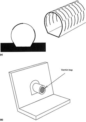
FIGURE 2.1 (a) Plastic pipe, well designed and properly laid so as to achieve both interception and discharge. (b) Headwall and splash surface.
drainage scheme. Usually there is an existing ditch, stream or even a nearby storm-water drain that is suitable, although use may have to be negotiated with the rightful authority. Failing any of these the use of boreholes, soakaways or even a pump may have to be considered. Boreholes and soakaways, however, seldom provide a satisfactory solution unless somewhere below they can be positively linked through to a permeable stratum with a consistently low watertable.
Pumps, either electric or diesel, are used mostly for the drainage of agricultural land but are also available for use on small areas such as sports grounds. They are generally capable of operating automatically when water in a sump reaches a given height. A solution on these lines, however, is not recommended, except in very special circumstances, as such equipment, with its ancillary housing, is expensive to install and requires periodic attention to ensure that it is always in satisfactory working order. Useful information on pumping systems is given in the MAFF leaflet, No. 14 Pumped Field Drainage.
All outfalls into ditches should be above peak high water wherever possible and at least 150 mm (6 in) above normal water level. The outfall pipe should discharge through a properly built headwall and be fitted with a flap valve or vermin trap (Figure 2.1(b)). At least the last 1.5 m (5 ft) of buried pipe should be of a rigid type, held firm by being closely packed around with soil.
Differential settlement of the pipe and the headwall can lead to pipe displacement or fracture where the two meet. It would be wise, therefore, to check on the continuing efficiency of these junctions a year or so after construction.
As a general principle, to avoid a situation where intercepted water cannot easily be cleared, work on drain installations should proceed backwards from outlet to inlet.
Drain falls
Pipe drains should not be laid to a fall of less than 1:200 as it is difficult to lay a drain to such a small fall uniformly; steeper falls are preferred. Mains should generally be laid to a slightly steeper gradient than laterals. This will ensure that there is no check to flow water at the junction.
Drain falls should be kept as uniform as possible. Any reduction in fall along a drain run may slow down the rate of flow to the extent that silt disposition will occur and the pipe eventually becomes blocked. Sharp bends should also be avoided unless an inspection chamber with silt trap can be provided at the change of direction.
Distance between laterals
The spacing between laterals depends on:
- climate, pattern of use and budgetary constraint;
- the expected efficiency of other parts of the system—the slope andtrueness of the surface, the nature of the soil, and the capacity of any auxiliary system installed to intercept surface water and pass it on.
In practice the rate of drainage that is adequate for most clubs is likely to be between 25 mm and 50 mm (1 and 2 in) per day depending on geographical location and nature of use. To achieve this most soils in Britain require a two-tier system of artificial drainage consisting of a lower tier of pipe drain laterals crossed at right angles by an upper tier of closely spaced sand/ gravel slits (Chapter 3, page 49 et seq provides a full discussion of ‘tier systems’). Details of spacings, depths, etc. are worked out on the basis of a simplified version of Hooghoudt's drain spacing equation (Chapter 4, page 57 et seq),much depending on the characteristics of the backfill materials used in the slits. For this type of design the spacing of the laterals commonly works out at around 10–20 m (11–22 yards).
Schemes aiming to avoid the need for some form of artificial, auxiliary system to intensify surface interception cannot expect to approach a satisfactory design for winter use, even under favourable conditions of slope, soil and discriminate use, without laterals spaced less than a maximum of 4 m (41/2 yards) apart. However, reducing pipe spacing below 4 m (41/2 yards) is unlikely to be economical compared to the cost of a two-tier system, unless the pipes and trenches are miniaturized.
Depths of drains and width of trenches
Extreme depth can add greatly to the cost, generally for no useful purpose. Extreme shallowness, on the other hand, may considerably reduce the efficiency of interception and court damage when the trenches are crossed by heavy equipment. For laterals the depth to the surface of the pipe should exceed the depth of the freely permeable topsoil and should exceed, by a margin of at least 150 mm (6 in), the depth to which equipment will later be operating to install ancillary drainage such as sand/gravel slits or mole channels. Even then it is always worth checking, by means of an initial demonstration on site, that the technique which the contractor proposes to use for the installation of ancillary drainage will not risk indirect pressure on the pipe system. The gravel backfill used in pipe trenches is loose, uniform in size and somewhat rounded, and will readily transfer pressure downwards. This may lead to pipe damage when the rotating tines on the excavating arm of a mechanical trencher exert downward pressure as they circle round the far end of the boom (section 11.4, pages 177–179). Where heavy, wheeled equipment is used, it may be necessary to adopt the precaution of using temporary bridging planks over each pipe trench to take the weight of the installation machinery as it crosses.
In practice laterals generally should be laid in trenches not less than 450 mm (18 in) nor more than 750 mm (2 ft 6 in) deep, although as much as 900 mm (3 ft) or more, may be necessary where the drain has to be deepened along its run to obtain the necessary fall. Where there is to be mole drainage or subsoiling the depth should not normally be less than 650 mm (2 ft 2 in) nor more than 750 mm (2 ft 6 in), the distance between the top of the pipe and invert of the mole channel being not less than 100 mm (4 in), preferably 200 mm (8 in).
It must be remembered that the deeper the trench, the greater will be the cost of excavating and carting away soil and then replacing it with permeable fill. For this reason also it is important to ensure that the width of trenches is kept as narrow as possible, consistent with ease of pipe installation; generally around twice the pipe diameter.
The difference in the outside diameter of perforated plastic piping and the clay tile equivalent should always be borne in mind when specifying depths and widths of excavations.
The depths of main drains must depend upon the layout and design of the system as a whole—for example, the depths of the laterals or the level of the outfall. For this reason, when designing, it is always wiser to work back from the final outlet so that any limitations on depth and fall are immediately apparent.
In tight situations it is the depths of the peripheral, interceptor drains and ditches that can be a problem. To be effective along the downhill margin of a site they have to be deep enough to help control any ground watertable and deep enough to allow for unrestricted discharge from any field drains.
Pipe junctions
To avoid any obstructions to the flow of water from branch drains, purpose-made angle junctions should always be used. Manufacturers offer a range of such junctions but all too frequently they are not available on site. The flash discharge, characteristic of modern sports field drainage, will not benefit from a sudden check to flow in a lateral main through an indirect gravel bridge; and neither will a flow in a main benefit from being checked by the end of a lateral protruding into it. Such checks will encourage silting and a progressive deterioration in efficiency.
Pipe size, flow rates and overall design
Choice of pipe
There are a large number of pipes on the market that can be used for land drainage purposes but, for the majority of sports ground schemes, the types most generally favoured are the clay tile pipe and the flexible plastic pipe.
Sports fields are fairly restricted in their pipe drainage requirements:
- they seldom exceed 6 ha (15 acres);
- gradients normally lie between 1:200 and 1:40;
- design rates are generally adequate at a maximum of 50 mm (2 in) per day.
For an overall design rate of 50 mm per day and a gradient of 1:100, maximum pipe sizes normally do not have to exceed 150 mm (6 in) internal diameter, and this maximum size is required only for the main running to the final outfall of a 2 ha (5 acre) field. For an area the size of a football pitch the maximum requirement for the pipe at the outfall may well not need to exceed 100 mm (4 in).
Table 2.1 has been prepared to provide guidance on a selected range of pipe sizes currently in use for sports field drainage projects. Rates of flow and areas served are also given but, because type of pipe and availability are bound to vary with time, these are offered merely as general guidance.
Flow rates are of value for indicating the capacity required in the final outfall. A speed of flow in excess of 30 cm (1 ft) per second is likely to be adequate to carry fine sediment out of a pipe drain line and this should be exceeded for all the examples listed, but only when the drain is running full. Hence there is some virtue in not being over generous in pipe size provision. Joints on mains need to be sealed where there is a risk of speeds of flow in excess of 150 cm (5 ft) per second but this applies only to those examples bracketed.
To calculate speeds of flow, measured in centimetres per second, from information on flow rates, in litres per minute, and internal pipe diameter, in millimetres, use the formula
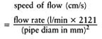
The recommendations in Table 2.1 include an allowance to limit the risk of surcharging in the mains but no allowance for silt deposition limiting effective pipe diameter in either main or laterals. In addition they assume an overall drainage rate of 50 mm (2 in) per day to be cleared through the installed drainage system. The reasons behind these choices need to be discussed as there are circumstances in which some further modifications may be justified.
Surcharging and silt deposition
The absence of any safety margin built in to avoid surcharging in laterals is acceptable, particularly under sports field conditions, because of the freedom for water to escape as well as enter throughout their length. The runs are relatively short (less than 100 m) and gradients generally low (less than 1% when installed diagonally across slope) so that water can readily back up along the length of the pipe without developing sufficient head to raise it onto the surface. Also, in a modern sports field drainage installation, there is an abundance of easily accessible and stable storage space for excess water in the gravel fill around and above the pipes, and in the base of the slit systems to which they are linked. Occasional surcharging under these conditions need not be a problem and may be an advantage. The enhanced scouring effect when pipes are running full will help to clear small accumulations of sediment along to the silt traps.
By contrast, though mains may be open (perforated) throughout their length as when acting also as part of a peripheral catchment system, many are closed (unperforated) with access only where they link to laterals. In either case, however, they tend to run fuller than laterals throughout their length and, in sports fields, run for longer distances and at steeper
TABLE 2.1 Pipe performancea. Area served at overall design rate of 50mm/dayb
gradients than the laterals feeding to them. They must be protected, therefore, from surcharging or they will transfer their problem back along the laterals, particularly those entering lowest down slope. It is for this reason that the recommendations quoted for mains in Table 2.1 include a safety margin to protect against surcharging. This is particularly important with the ‘flash discharge’ potential of modern slit systems. It also justifies the further precaution of always erring on the generous side when faced with a choice between two reasonably close, pipe size options.
Mole drainage systems work best in cohesive soils, e.g. soils such as clays. In such cases mole drainage is unlikely to increase the risk of siltation in the laterals, because moles should never be installed in other than cohesive soils. However, any risk of surcharging within the laterals into which they empty should be avoided. The unstabilized mole drainage crack and tunnel system is very liable to collapse if allowed to remain full of water. In an effort to extend the effective life of such systems care should be taken to keep the top of the pipe at least 20 cm (8 in) below the normal 450–525 mm (18–24 in) moling depth and an additional 10% margin of safety should be included in the carrying capacity of the pipe system throughout.
When corrugated pipes are used, either for mains or laterals, the recommendations in Table 2.1 may have to be modified to take account of extremes in the pitch of the pipe corrugation. The value shown will underestimate by 10% the carrying capacity of a corrugated pipe where the pitch of the corrugation is less than Wh of the diameter of the pipe, or over-estimate by 10% where it begins to exceed 1/7th
Because sports fields generally are fairly flat, small irregularities in the surface can make it difficult to install pipes to an even gradient and deposition of silt in the low spots may ensue. In addition, the supply of silt may be enhanced by the open nature of the permeable fill, the narrowness of the trenches and the weak structural state of the soil. As no allowance is made for effects of siltation in the recommendations listed in Table 2.1 the recommendations given are most appropriate for cohesive soils, over 35% clay.
For very unstable soils, mostly very fine sand and silt with less than 15% clay, it would be advisable to design the pipe layout with numerous silt traps allowing easy access to pipes for clearance. Alternatively, trenches may be lined and pipes wrapped in appropriate synthetic filter fabrics. A small increase in pipe size alone will not be sufficient.
For all other soils (i.e. soils 15–35% clay) it would be advisable to make a standard allowance of an additional 10% in pipe capacity as a safety margin against the consequences of a small amount of siltation restricting flow. This applies particularly to open mains where there is unlikely to be free access to an under-bedding of gravel into which any initial flush of silt in a new construction might otherwise escape.
Significance of overall design rate
The advice on safety margins so far given is aimed primarily at ensuring the internal integrity of the drainage system, avoiding troublesome bottlenecks so that once free water has been intercepted it can flow smoothly right through to the final outfall. However, the scale of the whole operation is conditioned from the start by the efficiency with which the overall design rate meets the problems posed by the incident rainfall. In Table 2.1 the assumption is made that the objective is to be able to clear up to 50 mm (2 in) per day through the installed drainage system. In effect this could amount to at least 60 mm cleared in total if a pessimistic view is taken of the contribution likely to be added by natural seepage which bypasses the installed system. The significance of the 50 mm per day target is that it comes very close to the maximum which agro-meterologists assume to be appropriate, in England and Wales, for mole-drainage assisted schemes, designed to meet the needs of all-the-year-round productive horticulture, the nearest equivalent we have to the demanding requirements of sports turf (last column, Table 1.2). This target is reduced in the drier south-east of England to something close to 30 mm (l1/2 in) and rises to over 60 mm (21/2 in) in hilly districts in the west.
However, the importance of this range of variation for sports turf should not be exaggerated as it need amount to no more than selecting the less generous or more generous option, according to circumstances. The cost difference will be a relatively small item in the overall cost of the drainage installation.
Short periods of intense rainfall may occur at anytime, but amounts of the order of 5mm (1/5 in) can usually be accommodated within the temporary storage space immediately available in the topsoil, the pipes, and the abundance of gravel fill in a modern slit drainage system. Storm conditions are probably best provided for by grading the surface so as to clear surface water off the playing area, to storm channels around the periphery.
Filling material over pipe drains
All lateral pipe drains should be covered with permeable fill to help achieve their function of interception. The grade, nature and depth of the fill layers will be dependent upon the type of drainage system to be installed. Where clay pipes are used the fill immediately over and around them must be large enough to ensure that it cannot enter the pipes at joints where gaps may occur as a result of differential settlement. A suitable specification for use with clay pipes might be
Backfill to 100 mm (4 in) over the pipe with 20–30 mm 3/4 –1 1/4 in) ‘beach’ or clean stone, followed by a layer of 5–10 mm in) clean trench gravel (e.g. SN7 in Table 7.1) up to within 150 mm (6 in) of the surface.…
Where plastic pipes are used the ‘beach’ or stone should be omitted and the trench gravel layer taken right down to the pipe. This reduces the number of backfilling operations and allows a small saving in cost. In addition, the tradition of using 95 mm (33/4 in) clay tiles as laterals where the smaller 60 mm (23/8 in) plastic pipes would do should be discouraged as the wider trench required must necessarily involve an additional cost for extra excavation and backfill.
Unless serving also as a peripheral catchment drain, the main need function only as a collector for the laterals to which it is linked. As such, it need not be perforated or the trench backfilled with gravel. However, as some mains may also act as peripheral interceptors of extraneous site water, the pipe used in these instances will have to be perforated and the backfill organized as for pipe laterals.
With laterals it is necessary to determine whether the gravel backfill should be topped to the surface with topsoil or with sand. If the laterals are to be fed by a closely spaced system of slits, topping the laterals with sand becomes superfluous. Putting back neatly cut, carefully preserved, 50 mm (2 in) thick turfs on 50 mm (2 in) of good topsoil, supplemented with a phosphate-rich fertilizer, should not noticeably affect the efficiency of the system and will make sward restoration easier. However, to avoid any risk of the soil weeping down into the gravel, a 50 mm (2 in) layer of blinding sand (SN10 in Table 7.1) should be inserted between the soil and the gravel (Figures 4.2 and 11.1). This is particularly so where lateral trenches are excessively wide, as may well be the case when dug by a hydraulic excavator in stony ground.
On the other hand, laterals in narrow trenches at fairly close spacing and not augmented with any slit drainage, should always be topped with sand in order to retain the capability of infiltering surface water. The sand used should be a coarse-to-medium blinding sand (SN10 in Table 7.1), extended to 50 mm (2 in) above surface level with a topsoil sand compost (SN16 in Table 7.1) to allow for initial settlement and provide a reasonable seed bed. For further information and more detailed advice on establishing grass on sand-filled trenches, see Chapter 2, page 41.
On new grounds, the need to preserve the sand topping of the laterals uncontaminated by soil presents difficulties when there is a need for a measure of surface cultivation prior to seeding. The only way to avoid this completely is to defer the installation of pipe drains until after the new sward has been established and the soil firmed into place. This is not always practical, however, and the establishment of the initial sward, with no drains in place, may be adversely affected by surface waterlogging. The aim, therefore, must be to prevent too intimate a mix of soil and sand by cultivating parallel to the laterals rather than across them.
If sand, or sand/gravel, slit drainage is intended, or is a future possibility, it is essential that the backfill of the pipe drain is not so coarse that the sand or gravel within the slit will run into the backfill of the drain, impeding flow and causing the level of the fill in the slit to drop.
Due priority must be given from the start to ensuring the compatibility of all the materials likely to be used to achieve a fully integrated construction that will drain efficiently, whether or not all stages of the construction are to be implemented immediately. The task of upgrading an existing construction is all too often hampered by lack of forethought on the part of those responsible for the initial design. Because of this, special consideration is given in Chapter 7 to the specification of appropriate materials, in particular, soils, sands and gravels.
Installing pipe drains
Normal trenching
As explained in the section on filling material over pipe drains, the details of this operation vary according to whether the gravel backfill is extended to the surface with topsoil or sand.
The initial procedure for trenching in laterals normally involves excavating and carting away the soil as work proceeds. If the gravel backfill is to be covered by topsoil and turf, these should be excavated separately and placed beside the trench, ready for replacement. Excavating machinery which transfers the soil directly onto a trailer by appropriately screened conveyer belting should leave a clear surface free of loose soil and stones.
Every effort should be made to ensure that subsoil from the trenches does not become mixed into topsoil. If this occurs it may have harmful effects on permeability and nutrition.
The trenching procedure for a main will be similar to that for a lateral if its function is not only to collect water from laterals but also to act as a catchment drain in its own right, e.g. along the perimeter of a site. Because in this case the pipe will have to be perforated, soil from the trench will have to be removed off-site and replaced with permeable fill. However, a main whose purpose is solely to collect water from laterals and convey this onward to an appropriate outfall will not be perforated, entry being restricted to the purpose-made junctions with laterals. In this case, the need for permeable fill does not arise and subsoil as well as topsoil should each be preserved separately for replacement to appropriate levels after the pipes have been laid.
It is most important that all piping is laid accurately to correct lines and falls. Clayware drains should be closely butted together and the top end of each run sealed by a broken tile. Plastic drain runs should be sealed by plugging with the appropriate end-stop accessory. All drain runs should be checked for accuracy of line and gradient before being buried under backfill.
The order of installation is: the outfall, followed by inspection chamber and silt pit; then the main, complete with purpose-made pipe junctions for linking up with the laterals; the laterals; finally, the sand or sand/gravel slits. Following this sequence ensures that any water invading the workings during construction can be cleared without difficulty.
Sophisticated techniques such as laser beam projection are increasingly employed to ensure that levels and falls are consistently true and uniform.
As PVC pipes are liable to become brittle at low temperatures, they should not be installed, nor permeable fill placed over them, when the air temperature is less than 0°C.
Trenchless drainage
On sites where good lengths of drain run are possible and the work is reasonably straight-forward, the ‘trenchless’ system, as commonly used for agricultural drainage, is sometimes a more economical system to employ. This type of drainer lays flexible plastic piping with a mole plough pattern slitter, and back-fills the slit with small stone or gravel in one operation, without the need for excavating and removing any soil. The employment of the trenchless drainer is generally confined to the installation of drains prior to the preparation of a seed bed. This requirement is dictated by the fact that the machine causes a considerable amount of unwanted surface heave that may have to be trimmed off level.
On grounds where major regrading is necessary, trenchless drainage should be installed before the topsoil is replaced and the gravel backfill brought right up to the exposed subsoil surface. Slit drainage can be organized through the topsoil later.
A trenchless drainer can be tractor drawn or winch operated, the latter method reducing the risk of wheel rutting. Either way, it is necessary to dig a hole or enlarge the mains trench at the beginning of each drain run so that the plough can be eased down to begin its run at the correct depth.
Silt pits and inspection chambers
Silt pits (sometimes known as silt traps or settling chambers) are required wherever there is a marked change in the direction of a main drain, or a reduction in fall: that is, where a slowing down of flow may lead to an accumulation of silt and perhaps the eventual blockage of the drain run. They are required particularly at mains junctions and at the final junction to the outfall. Where water from an open ditch enters into a pipe drain there should be a silt trap as well as a grating.
Internal dimensions of silt pits should be not less than 900 mm×600 mm (3 ft×2 ft) and the floor should be at least 300 mm (1 ft) below the outlet pipe (Figure 2.2).
Inspection chambers (without silt pits), are smaller and less expensive than silt pits. They are useful for augmenting silt pit provisions where there are minor changes in direction or fall in long mains which might otherwise be difficult to inspect.
Internal dimensions for inspection chambers should be not less than 600×600 mm (2 ft× 2 ft) and the floor should be at the same depth as the invert of the outlet pipe, i.e. where the base of the pipe turns inwards.
It must be emphasized that silt pits and inspection chambers are an essential provision for the proper maintenance of a drainage system. In addition to routine work, such as periodic removal of silt and the rodding of mains, flow at the vital points can be regularly monitored and unusual changes investigated. Because of their cost, however, they are not always provided on sports grounds to the extent they should be. There is no doubt that without at least a minimal provision, the task of checking the efficiency of the various sections of the system and of locating and repairing defective lengths of drain, is likely to be much more difficult and time consuming.
For ease of access, manholes should be sited outside the main playing areas. If this is not
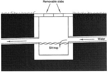
FIGURE 2.2 Silt trap.
practicable, or there is likely to be unauthorized interference, the covers should be sunk 150 mm (6 in) below the level of the finished surface and covered with soil and turf. Sunken manhole covers should be of thick reinforced concrete, sufficiently strong to withstand the passage of tractors, rollers, mowers, etc. but capable of being manhandled. The thickness of the covers should be 75–100 mm (3–4 in) according to span, and countersunk lifting rings should be fitted. If exposed at surface level, heavy duty covers can be used and should be sited slightly below the surrounding turf so as not to interfere with mowing operations. Their positions, particularly if below ground, should be carefully measured and recorded. Inlet and outlet pipes should be salt-glazed or unperforated plastic.
Ancillary items
Important features of a drainage scheme such as purpose-made junctions, silt pits, inspection chambers, end-stops, headwalls, flap valves and vermin traps are often either inadequately provided or omitted altogether. They have their purpose and should always be included in a quality construction.
2.1.3
Iron ochre—a special problem
Silt pits and inspection chambers assume particular importance in areas where the environment is conducive to the formation of iron ochre (hydrated ferric oxide). It is not a common problem, but tends to occur in proximity to waterlogged places where iron in the soil forms iron sulphides (pyrites). Under certain conditions, such as when air is admitted to the system, the sulphides are oxidized to ferrous sulphate by sulphur bacteria. This ferrous iron may then be further oxidized, either chemically or by iron bacteria such as Thiobacillus ferroxidans, to a soft, often gelatinous orange/yellow material which, on drying, becomes powdery, fibroid or a solid deposit of iron oxide (rust). Such deposits are often found in the vicinity of shale rock and coal seams where there has been disturbance for mining but are generally far more associated with peaty soils, or very acid soils close to peat deposits. Ochre deposition, often accompanied by an oily film, may show up along the banks of ditches, in isolated pools of water or where spring water emerges.
By introducing oxygen into the soil, a drainage system may set in motion a chain of events which might not otherwise have occurred. Iron ochre deposits, in manholes or at the outfall, may be the first indication of the presence of an ochre problem which, on further investigation, may be seen to affect the pipes, the permeable fill in the trenches and the adjacent soil. Hitherto, the measures most likely to be employed to dislodge ochre deposits have been mainly pressure jetting and/or rodding of the pipes. Recently experiments with weathered conifer bark in field trials at the Macauley Institute of Soil Research (Vaughan et al, 1984) have shown encouraging initial results in absorbing ferrous iron from solution before it is oxidized to the ochre form. These investigations are still continuing.
Where the problem of iron ochre contamination is occurring, or is anticipated, it is suggested that, as a first step, water reaching the site from springs or underground seepage should be intercepted before it reaches the pitch areas, diverting it into a ditch system. The layout for the drains should then be designed to ensure that water from the open ditch or trench system discharges into an inspection chamber before passing on into a pipe drain. In severe ochre cases, chambers should be positioned at 30–35 m (33–40 yards) intervals along the main until the outfall is reached. In each chamber (1 m diameter) four or five loose-weave polypropylene sacks containing a total of approximately 80 kg (dry weight) of weathered conifer bark should be placed, the sacks being arranged in the chamber sump in such a way that inlet water passes through them before reaching the outlet. The bark should last at least six months before requiring replacement. In less severe ochre cases, the drainage pipes should be surrounded by a 1:1 mixture of conifer bark and gravel during installation.
2.2
Auxiliary soil drainage—assisting water movement through the soil
2.2.1
Soil by-pass systems (slit drainage)
Slitting can be looked upon as the sports field equivalent of agricultural mole drainage. Both procedures aim to improve surface infiltration and, by a direct continuous route, move the excess water rapidly sideways into the backfill over pipe under-drains. It is the continuity of the route for free water flow, right through from the surface to the assured outfall, that is so important and must be maintained. With mole drainage the route is simply the crack and tunnel system formed by the special plough drawn through the soil. With slits, the route, once excavated, is stabilized against collapse by freely permeable backfill. Unlike surface spiking, these systems are intended to aid infiltration and discharge without relying on much help from the fine pore system in the soil itself.
Mole drainage
Moling and subsoiling
Mole ploughing and subsoiling are similar procedures involving a robust, sharp-edged blade being sliced vertically through the soil, drawn downwards to its working depth by the action of a chisel toe protruding forwards from the base of the blade (Figure 2.3).
Subsoiling is primarily aimed at breaking up soil compaction and improving surface infiltration by the creation of a series of cracks spreading obliquely upwards from either side of the chisel end of the plough blade. To encourage extensive cracking this procedure is best
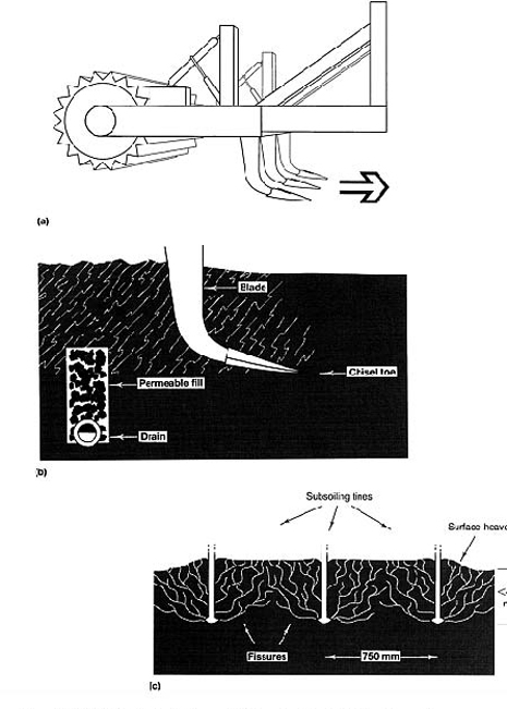
Figure 2.3 (a) Multi-tined, vibrating subboiler and roller. (b) Subboiling action viewed from one side. Used to lift the topsoil and create cracks, allowing surface water to enter and excess to clear slowly in the general direction of the underdrains. Rooting should benefit, at least temporarily, from the improved air/water balance. (c) Subsoiling action viewed from behind.
carried out when the full depth of the soil being treated is dry.
Various modifications have been developed to improve upon the basic subsoiling equipment. Wings have been added to the subsoiler shoe increasing the area of soil disturbance by as much as two to three times. Miniaturizing the equipment, linking several subsoiling tines together on a rigid or vibrating frame, sloping the tine legs back at an angle of 45°: all these are approaches aimed at improving the effect or minimizing surface disruption when working at shallow depths.
Moling aims to provide both for infiltration and discharge and involves pulling through a bullet-shaped expander behind the toe of the subsoiling plough so as to squeeze out a continuous, well-formed tunnel along the line of origin of each set of outwardly diverging subsoiling cracks. Moling, therefore, is best carried out in the spring or early summer when the topsoil has dried out enough to crack, but the subsoil at moling depth is still moist enough to shape into a well-formed tunnel (Figure 2.4).
Moling and subsoiling are both used in agriculture but even on favourable soils and after satisfactory installation, their efficiency can be limited by the panning effects of subsequent cultivation and wet-weather poaching by animals. Their passage through established grass can lead to a degree of surface disturbance requiring special attention if the means of restoration is not to hazard the long-term objectives of the initial moling operation. For example, ploughing, harrowing and seeding may immediately restore a flat surface but the shearing effect of a plough share as it is drawn horizontally through the soil, aggravated further by tractor wheel compression, can interrupt the continuity of the vertical cracking system installed by the initial mole-draining procedure. Where possible, therefore, it is more effective to mole after ploughing, thereafter merely harrowing to true.
Depths
The preferred depth for moles is 600 mm (2 ft); they should never be less than 450 mm (18 in), commonly 525 mm (21 in). The pipe drains into which they discharge should be at a sufficient depth to ensure that when the moles are drawn through the backfill their invert is at least 150–200 mm (6–8 in) above the top of the pipe. There should be enough distance between the pipe drain and the boundary of the field, usually between 10 and 15 m (11–17 yards) to allow the mole plough to reach working depth before crossing the first of the pipe trenches.
Mole size and spacing
The standard mole is 75 mm (3 in) in diameter but can be fitted with an expander to increase the diameter of the channel to 90 mm (31/2 in) or 100 mm (4 in). When conditions are sufficiently dry, fissures caused by the action of the mole extend upwards at an angle of about 45°. The spacing of the moles depends on the depth of the mole invert and should normally equal four to five times this figure. Thus, at a minimum depth to invert of 450 mm (18 in) the spacing ideally should be 2 m (61/2 ft) and certainly should not exceed 2.7 m (9 ft).
Gradients
A gradient of 1:200, or less, may result in a flow that is so sluggish that the mole channel fills with water, causing the roof to collapse. On the other hand, with too fast a flow, excessive scouring takes place and again blockage may occur. These extremes should be avoided, either by keeping the runs as short as possible or, in the case of a steep slope of 1:40 or more, by drawing the moles diagonally across it.
As mole ploughs are not normally equipped with a grading device for ensuring an even fall on the mole drain they cannot be operated successfully on undulating land. Generally the most that manufacturers provide is a long and heavy beam that slides along the ground to
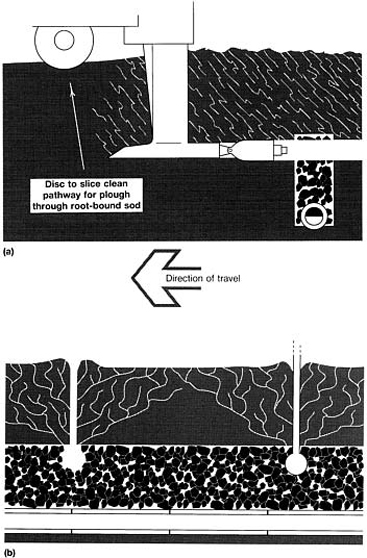
FIGURE 2.4 (a) Mole ploughing across piped system of underdrainage. Blade, toe, mole and expander of chisel plough producing subterranean tunnel, at approximately 500 mm (20 in) depth. (b) Mechanically induced crack system improves interception and links mole tunnel through to the surface. Intercepted drainage water cleared through mole tunnel to permeable fill over pipe in drain trenches. Ideally tunnel system formed in moist soil; cracks induced by mechanical disruption of dry soil, therefore timing critical. Use tractor wheel or roller along line of disturbance to re-true the surface. Worm action will then be required to keep the surface open.
prevent minor irregularities from affecting the general grade of the mole. However, laser control is now available as a more efficient alternative.
Practical constrains liable to limit the effectiveness of mole drainage
To maintain a beneficial effect it must be possible to repeat the moling operation at regular intervals, something to which a farmer can adjust, but much less so a groundsman.
Factors tending to promote crack and mole channel collapse are as follows.
- Soil inadequately clay-rich—less than 35% clay and especially soils less than 15% clay.
- Poor installation because of inappropriate soil moisture state at the time of installation.
- Wet rather than dry weather immediately following installation, preventing maturation of the newly exposed soil surfaces.
- Inadequate slope and imperfect grading of the mole channel leading to water ponding within the channel and increasing the risk that the adjacent, saturated soil will slump.
- Excessive slope or excessive length of run increasing the risk of disruption by scour.
- Boulders and other obstacles in the soil repeatedly impeding progress.
Mole drainage and subsoiling in sports fields
Though, at first thought, moling would appear to be an ideal method of improving soil drainage it is generally much less useful in sports fields than in agriculture. When dealing with a compact soil it is impossible to introduce extra pore space without displacing the soil upwards. The consequent surface disruption may well require so much renovation that such an operation could not be contemplated annually. It is only when the soil is already maintained open by earthworm activity that moling can complete the task of realigning some of the available space to effect rapid lateral discharge without undue surface disruption. This is likely to be the case only on a new site taken over in good condition from agriculture and maintained biologically active thereafter.
With discretion in use, however, mole drainage is a relatively cheap operation and can be made to work on a suitable site with a suitable soil texture and an adequate level of earthworm activity. For example, on a clay-rich, worm-worked soil, sloping uniformly at a gradient of 1:60, moles should be drawn diagonally down slope to cross pipe laterals running in parallel succession at 30 m intervals down the other diagonal. To help leave a level surface, spacing of the mole runs should be reduced to approximately twice working depth, e.g. 1 m (1 yard), so that the whole surface is loosened and lifted uniformly. To avoid tearing the grass sward unevenly, a disc should be run ahead of the blade of the mole plough, ensuring that the sward will be neatly slit apart and as neatly restored by immediate rolling. There is much to be said for working at half the spacing of the tractor wheels. This will allow one tractor wheel to roll back any surface disruption along the previous run as the next run is installed.
Subsoiling, which is essentially a soil-cracking operation, is useful as part of a soil-deepening procedure at the cut end of a cut-and-fill operation, or for the relief of compaction caused by heavy machinery during construction. Like moling, it may also be used to good effect on a potentially good soil to co-operate with earthworms in the relief of surface compaction prior to sward restoration in spring. However, such a soil-opening operation will not necessarily benefit grass growth unless the soil structure restored is adequately water-stable and the extra water infiltered can be cleared before it adversely affects soil aeration.
Both moling and subsoiling will tend to bring obstacles impeding progress up onto the surface. On bouldery soils and tip sites this can be disastrous and may require the abandonment of the whole operation. Prior to starting on any such operation, therefore, examine the soil to the full working depth of your equipment. Water is more acceptable on the surface than stones, glass or scrap-iron!
Where a system of sand-and-gravel stabilized slits has been introduced soil drainage may have been greatly improved without necessarily improving the soil's structural state between the slits. This may lead to a sward very sensitive to drought because its roots cannot fully exploit the soil in depth. Subsoiling to relieve compaction at this stage, however, will hazard the stability of the slit drainage system by creating horizontal cracks into which sand fill may weep away sideways. Only subsoil through a slit system where, prior to subsoiling, the whole surface has been carpeted with a thick covering of sand to preserve sand continuity from the slit through to the surface. When time and resources allow, it is better, on a bad site, to first install the pipe underdrains, then improve the physical condition of the soil by subsoiling before going on to install slit drainage.
In the hands of a conscientious, skilled groundsman, suitably equipped and familiar with both the technical procedure and the need for correct timing according to soil condition, moling and subsoiling can be used effectively on sports fields to aid soil drainage. These are not techniques that lend themselves to effective use by a busy contractor, however, as correct timing is of the essence.
Sand and sand/gravel slits
The basic requirement for ensuring satisfactory drainage for winter games on a non-sandy soil is a sand or sand/gravel slit system linked below to pipe underdrains. The actual efficiency of such a system depends on the type of slits installed, their spacing, length of run and the continued effectiveness of their permeable link through to the surface.
All the main design features of a slit system, except slit spacing, can be resolved by calculation. Once surface run-off has entered a slit system much can be done to design and choose suitable materials that will ensure that a certain design discharge rate can be maintained through the slits to the pipe underdrains and final outfall. Slit spacing was initially determined by reference to the spacing used in agricultural mole drainage and by practical experience of the extent to which a benefit could be felt underfoot immediately after rain, either side of a lateral pipe drain. Both of these pointed to spacings of no more than one pace. Subsequent unhappy experiences with schemes utilizing wider spacing have tended to confirm the practical value of a 1 m (1 yard) limit. However, this feature of design will continue to be a subject for debate as so much depends in practice on the smoothness and slope of the surface, the extent to which access to the slit is preserved and protected by a surface covering of sand, and the standard of efficiency demanded. A typical scheme, evolved and tested by trial and error over the past 20 years, is illustrated in Figure 11.1.
The slits are normally formed by machine and vary in width from 25 to 75 mm (1 to 3 in). Often the width is determined by the type of trench excavator employed. Slits greater than 38 mm (l1/2 in) are usually formed by excavation, therefore it is necessary to remove and cart away the surplus soil. In this operation great care must be taken to ensure that the excavated soil is not accidentally scattered and left lying on the grass surface for any length of time before being cleared away. With slits less than 38 mm (l1/2 in) in width the cut is usually formed by pressure from the blade of a subsoiling plough leaving no soil to be removed. Ground heave from this operation may be unavoidable, however, and any attempt to retrue the surface by rolling afterwards requires care to avoid capping the slit surface with soil.
Where slits are formed by excavation it may be found that the actual width of the slit dug out is greater than the rating for the machine. For example, a slit taken out by a trencher with a 50 mm (2 in) cutter may be found to measure as much as 75 mm (3 in) across in places, particularly on difficult, stony ground. If this is likely to happen, special care must be taken when calculating and costing the amount of backfill required.
The depth of slits will depend upon the drainage rate, the nature of the backfill materials, and the length of run between the relieving underdrains. Normally, depths range between 250 and 360 mm (10 and 14 in). However, soil impediments to trenching, or features of an existing pipe system may impose constraints necessitating a measure of compromise. There will then be a need for a compensating adjustment in some other feature of the scheme, such as slit width, slit spacing or the nature of the permeable fill.
Ideally, slits should run across the slope and be as near as possible to an angle of 90° to the pipe drain laterals into which they discharge. This will ensure maximum efficiency in surface water interception and minimum slit length before discharge.
Backfill for slits can be sand only or sand over gravel. If sand only is used the lateral discharge along which water will flow to satisfy sports ground drainage requirements is limited to less than 5 m (51/2 yards). In practice, therefore, the use of sand-only slits tends to be restricted to the improvement of existing schemes where there are already closely spaced pipe drains with backfill suitable for satisfactory sand slit linkage.
Where drainage schemes are designed from the start with slit drainage discharging into pipe laterals, it is desirable for reasons of economy to space the pipe drains as widely apart as possible. To achieve this the slits are backfilled first with clean 6–8 mm 1/4–3/8 in) trench gravel to at least half slit depth, followed by 5 mm (1/14 in) concreting sand (typically a blinding sand) to just above surface level. In this way the surface water infiltrates vertically through the sand and then flows laterally along the gravel layer to discharge into the gravel fill in the pipe-drain laterals. The spacings of the laterals are normally anywhere between 10 and 20 m (11 and 22 yards) according to the width, depth and spacing of the slits and the nature of their backfill materials.
There are calculations involved in all these design features which are described in Chapter 4. Schemes utilizing standard Stewart zone materials can make use of the simple relationship between the depth of the gravel layer in the sand/gravel slit and the acceptable length of run between laterals (Chapter 7, page 117).
For slits less than 50 mm (2 in) in width, a satisfactory grass cover can usually be established in a fairly short time by over-seeding with ryegrass and relying also on grass growth spreading in from the adjacent sward. The strong growth required can be encouraged by periodic, light applications of a nitrogenous fertilizer, plus irrigation if conditions threaten to become dry enough to halt growth. Where slit width is 50 mm (2 in) or wider, special surface preparation and seeding will probably be necessary to compete with the desiccating influence of the adjacent soil, weeds often succeeding where grass fails. The challenge is to achieve germination and establishment of grass on a sandy surface that is very liable to dry out and become impoverished of nutrients. Weather conditions are crucial, spring and autumn being the most favourable seasons.
The following type of procedure is required.
- Apply a pre-seeding fertilizer.
- Sow a ryegrass/fescue seeds mixture and bury by rolling or treading and covering with a topdressing of damp, amorphous, sedge peat or grass clippings.
- After germination apply small doses of general-purpose fertilizer, in liquid form, at fortnightly intervals, until the new grass has rooted sideways and become fully established. Irrigate if seedlings are caught by a period of drought.
Under no circumstances should play be permitted until grass cover over the slits has been fully re-established and the whole surface topdressed with a fine topsoil sand at a minimum rate of 80 tonne/hectare (30 tons/acre), i.e. a covering of 5 mm in) overall. For general advice on sward establishment and immediate aftercare see Chapter 6.
Transverse and longitudinal sub-surface gravel channels
Gravel channels, without pipes, are sometimes employed as one element of a drainage scheme where soil conditions are difficult for slit trenching below 200 mm (8 in) or thereabouts. As they are likely to have to be dug by the narrow bucket of a hydraulic excavator the width will be around 150–200 mm (6–8 in). The backfill should be gravel (e.g. trench gravel) from a depth of around 400 mm (16 in) to within 150 mm (6 in) of the surface and, thereafter, a blinding layer of sand (e.g. blinding sand) followed by replaced topsoil and turf.
A system of gravel channels will normally be best aligned so as to intersect both the gravel layer in the sand/gravel slits and the gravel fill in the pipe trenches at right angles. Ideally, pipes and slits should be aligned parallel to each other, on one diagonal across slope, and the gravel channels, intercepting the slits and delivering to the pipe underdrains, along the opposite diagonal.
Spacings will depend on the circumstances that condition the type and capacity of the slits but will normally be less than 5 m (51/2 yards). At these relatively narrow intervals the gravel channels could be designed to run for distances of the order of 20–25 m (22–27 yards) before themselves discharging into pipe underdrains.
A gravel channel link in a tiered system of drainage may be useful when a stony subsurface layer makes narrow trenching difficult for the full depth of a normal sand/gravel slit. It can also form the basis of a scheme designed to work on a soakaway principle. This may be necessary where there are difficulties over organizing an acceptable, final outfall for discharge off site. Such a construction has to be designed flat so as to stop drainage water surging about. The aim should be to hold any temporary excess in the slits and gravel channels below ground until it can leak away by natural seepage.
Mini-slitting
This is sometimes a preferred alternative to ordinary slitting where surface trueness is of particular importance, e.g. for hockey or a cricket outfield (see also section 11.2).
Mini-slits are formed by blade pressure, not excavation, and any slight heave can be settled by rolling along the line of the slits. The slitting machine is usually equipped with a sand hopper.
Mini-slit widths can vary from 15 to 30 mm (3/8 to 11/4 in) and depths from 200 to 300 mm (8 to 12 in) according to the type of machine used. Spacing ranges from 200 to 400 mm (8 to 16 in). The backfill should be 5 mm (1/14 in) concreting sand (i.e. a blinding sand).
As for the system involving gravel channels in the previous section, the mini-slits are probably best aligned diagonally across the slope, parallel to the pipe underdrains. They can then discharge into sand/gravel channels, running at 4 m (4/2 yards) intervals across the slope on the other diagonal, and the gravel layer in the sand/ gravel channels can discharge into the gravel in the pipe trenches.
Piped mini-slits
Pipe-based, mini-slits, spaced about 1 m (1 yard) apart, are a recent development. They are liable to be more expensive and less efficient than a slit/pipe drain combination where each separate tier of drainage can be oriented to perform at maximum efficiency according to function. However, they represent a useful compromise where the nature of the topsoil favours narrow trenching but the subsoil below 300 mm (12 in) would make deep trenching for pipe underdrains very difficult. As the orientation of the one trench determines both the angle of interception and the gradient for flow, the piped mini-slits should compromise on an oblique orientation across the slope. The precise angle chosen should give precedence to the need to assist discharge through the long runs of very narrow, 35 mm, corrugated pipe used to convey water all the way to the peripheral outfall. These very long runs of narrow pipe are not in themselves a specially commendable feature of the system, but they have to be made to function efficiently if the introduction of a pipe into each slit is to be justified.
This system certainly has merit where the subsoil does not favour deep trenching but elsewhere, though it may work, threatens to be expensive because it requires specialist machinery to install and is unnecessarily extravagant in the use of pipe.
Micro-slitting
Micro-slitting is an ancillary or remedial procedure involving the cutting of continuous, thin slits along the surface. The aim is either to enhance the directional flow of surface water towards a previously installed, standard, slit-drainage system, or to improve the vertical infiltration of surface water to a sand drainage layer immediately beneath an impeding soil cap. To extend their effectiveness they can be sand-filled, and where expense is no problem, can be used overall to replace or supplement a topdressing of sand.
On a small area the job can be done manually with a spade but there are now machines available that cut and fill several slits in one pass. The slits are of the order of 13 mm 1/2 in) wide, 100 mm (4 in) deep and spaced about 200 mm (8 in) apart. They may be sand-packed simultaneously, or topdressed with a dry, free-pouring, medium topsoil sand (e.g. SN12, Table 7.1), well brushed in. At the end of the operation, sand should be left, piled along each slit to compensate for any subsequent settlement, then rolled and maintained moist to encourage the grass to grow through. Interruption to play need be minimal.
2.2.2
Whole soil constructions
A shallow, ameliorated sand top, over a slit system and pipe underdrains
This is probably the most efficient system of drainage for winter games pitches but, being a two-tier system plus a 100–125 mm (4–5 in) thick ameliorated sand carpet, is significantly more expensive. If designed as such from the start, a slightly wider spacing of the slits than 1 m (1 yard) is permissible but should certainly not exceed 1200 mm (4 ft). The surface carpet can either be an imported and suitably ameliorated sand, or a loamy sand topsoil. Because the slits are well covered, this type of construction can provide the sort of true surface that is desirable for hockey.
Restricting the depth of the ameliorated sand carpet to around 100 mm (4 in) allows the grass to root down to the moisture and nutrient reserves in the soil below. Thus the sward will be protected from drought as well as waterlogging so long as the roots achieve and maintain contact with the soil below. Critical to success is the quick establishment of the sward (Chapter 11, page 168), the quality of the original buried topsoil (Chapter 11, page 167), and the appropriateness of the maintenance programme (section 11.3).
Irrigation should be available to assist during the initial stages of sand placement and during sward establishment. It may be required to help stabilize the loose sand surface against wind-blow or to safeguard the seedling sward against desiccation prior to roots reaching through to the buried soil beneath the sand carpet.
A deep, ameliorated sand top, over a gravel drainage bed
The deeper sand carpet supporting the sward in this system is mainly required for the finest turf surfaces used for golf and bowls. Because of the high cost of construction and maintenance this approach can seldom be justified for the construction of large areas of playing surface. The depth of imported and suitably ameliorated sand topsoil required is between 300 and 400 mm (12 and 16 in). This is laid over a blinded gravel bed with pipe underdrainage. Because the resistance of the sward to wear is minimal, great care and expertise is required in its establishment and maintenance (Chapter 10).
The gravel bed provides for the clearance of excess water filtering through from above but, when clear of water, it acts like an air lock to create a perched watertable in the overlying soil. Contradictory though this may seem, a gravel bed assists both drainage and water retention in the topsoil. However, the water reserve available to the sward is strictly limited to that in the topsoil and, as this could be exhausted in two to three weeks of dry summer weather, irrigation must always be on hand to avoid desiccation.
To provide the desired rate of drainage the ameliorated topsoil must contain at least 75% of the right kind of sand, e.g. a topsoil sand (Table 7.1, SN12–15). This in turn determines its depth and is critical for aeration, tractive efficiency, drought risk, seed germination, rooting and choice of grass species (section 4.2).
The bed should be 5–10 mm (1/14–3/8 in) gravel (e.g. trench gravel SN7, Table 7.1) topped by 50 mm (2 in) of concreting sand (e.g. blinding sand SN10, Table 7.1). The rate of drainage through the sandy topsoil layer should be taken into account when deciding on the thickness and the composition of the bed, and hence also, the spacing of the underlying pipe drains. Using 125 mm (5 in) of trench gravel to form the gravel raft under a bowling green will allow the pipe underdrainage system to be reduced to a single ring system under the peripheral ditch.
Full details of such a construction are given in section 10.3.
2.3
Timing of drainage work on established grounds
Drainage work on existing sports grounds often has to be carried out at a time most convenient to the users. However, in a country such as Britain, where weather conditions are so inherently variable, day to day, and only very approximately predictable according to season, the benefits to be derived from soil operations can depend very much on timing. For example, pipe drainage should be installed, ideally, in late spring or early autumn. Working in dry summer conditions is hard on trenching equipment and can also result in loss of turf, desiccated after disruption of the root system. Working in wet conditions creates unacceptable damage to the soil structure and to the grass. As has already been said, mole drainage is best carried out in the spring when the topsoil is dry enough to crack but the subsoil is still sufficiently moist to mould, and when there is every chance that the newly exposed soil faces will have a chance to be stabilized by summer desiccation. Sand slitting for winter games pitches should preferably be undertaken during the spring or summer months so that sward recovery can be achieved before winter sets in.
2.4
Sequence and timing of drainage operations on new grounds
On a site requiring major regrading, prior to the installation of pipe underdrains, there is no doubt that the topsoil will have to be removed to allow for redistribution of subsoil. However, there is then a choice to be made between installing the underdrainage prior to replacing the topsoil, or vice versa. The same choice arises when a new playing field surface is to be formed by spreading a shallow sand carpet.
There are two good reasons against laying pipe drains prior to topsoil placement:
- machinery may smear subsoil into the gravel or sand backfill, topping the drain trenches, thus hazarding the freely permeable link through into the topsoil;
- if, after using earthmoving equipment to regrade the subsoil, this equipment has to be retained to replace the topsoil after other equipment has been used to install the drains, on-site costs may increase enormously. The temporary removal of plant and equipment involves the doubling of haulage charges and possible delays in getting the machinery back again. Allowing the machinery to lie idle on site may incur the normal two-thirds standing hire rate.
Good reasons for installing drainage prior to topsoil placement are:
- elimination of any risk of subsoil contaminating the topsoil during the trenching operation;
- pipe drains can more satisfactorily be installed by the trenchless method. The subsoil presents a firmer surface than newly placed topsoil to work over and the ridges, heaved up either side of the trench, can be satisfactorily trued off prior to topsoil replacement.
When topsoil is replaced, unless it consists of sand, it should never by worked wet or its structure will suffer to the detriment of efficient drainage and vigorous grass growth.
In our climate, where heavy rain may occur at any time of the year, it is wise always to work uphill from an established outfall, avoiding any risk of the open trenches becoming flooded. Correct timing of operations during major construction work is very much a matter of judgement, often involving a measure of calculated risk.
2.5
Recording the position of pipe drains and slits
A record plan of a drainage scheme is a valuable document which should be carefully preserved for future reference. Not only is this information important for ensuring that the system is properly maintained but, without it, any extension in the future is difficult to plan and may lead to unnecessary duplication of drains, manholes, etc. Unfortunately, the detailed recording of drainage layouts in the past seems to have been badly neglected or, if it has been done, the plans seem generally to have been mislaid.
It is worth noting that where a scheme was grant-aided by the Ministry of Agriculture, Fisheries and Food, details of the work carried out will have been recorded and should be available from the Ministry's Divisional Office for a period of at least 20 years from when the grant was paid.
As soon as the installation of a drainage system is complete, the position of all branch, main and slit drains, silt pits, inspection chambers, outfalls, etc. should be accurately checked against the prepared plan and any alterations carefully recorded. Details as to depths, sizes and types should also be noted. The practice of marking important features, e.g. outfalls and hidden manholes, on nearby permanent surfaces, such as walls, can help with subsequent location.