Autodesk has a sunset policy for lower-cost upgrades from one release to a newer release—you must upgrade within a couple of releases to get the lower price. Otherwise, you must pay full price. As a result, most companies don't wait more than two or three releases to upgrade. However, I still find people using releases as early as R14, and many people I work with aren't using the current release.
This section is for those of you who have skipped releases and overlooked certain enhancements as a result. Even if you've been using a newer release for some time, you may have missed something useful. The following is a release-by-release list of selected new features that you should know about. New features are almost always carried over into subsequent releases.
AutoCAD 2000 was introduced in March 1999. It was the biggest thing to happen to AutoCAD since R12. Although I do industry training occasionally, I don't often do update training for a new release. For release 2000, though, I got so many requests that I developed an eight-hour update training session in response. Four new features in this release prompted me to say in the training, "This feature alone is worth the cost of the upgrade."
When the AutoSnap and AutoTrack features were introduced in AutoCAD 2000, they immediately became essential for quick and accurate drafting. I'd hate to use AutoCAD without them. If you made the mistake of turning these off, go back and look again.
AutoSnap allows you to acquire an object snap by hovering the cursor over a location until a small glyph (Autodesk lingo for small symbol) appears. Once it appears, you can use it as a tracking point. Some clarifications:
The object snap you're trying to acquire must be set as a running osnap, and the running osnaps must be on.
For a tracking line that extends an existing line on which you've acquired an end-point, you must have the extension osnap set as a running osnap.
For polar tracking lines to work with object tracking, Polar must be on, and Track Using All Polar Angle Settings must be selected in the Polar Tracking tab of the Drafting Settings dialog box.
Polar and object tracking are used to create objects at specific polar angles or at angles relative to object-snap points. You can set an incremental angle to which your cursor will snap. This allows you to enter distances using direct distance entry at any angle—no need for ORTHO. Object-snap tracking lets you see alignment paths from specific points as you draw. You can type in any increment, by the way, even if it isn't listed. I've found it helpful to use increments as small as one degree.
You can often reduce the amount of math you have to do in your head by changing the polar-tracking mode from absolute to relative in the Polar Tracking tab of the Drafting Settings dialog box. You can also type any value as the incremental value in Polar Tracking, although anything less than one degree is hard to control.
You can add hyperlink attachments to AutoCAD objects using the Insert Hyperlink dialog box. The links can be to any file, website, or layout, which can help you quickly go between Model Space and layouts in large drawings. Hyperlinking to files is often overlooked, but it may make more sense to link to files than to websites. Like websites, file locations and names can change. You must be careful to maintain the linked file. Because linked files are often on a network drive, selecting Use Relative Path can help maintain the link.
A drawback of hyperlinks is that they can't be seen on an object until you hover the cursor over that object. This makes them difficult to find.
To insert a hyperlink, select one or more objects, and then select the HYPERLINK tool button or run the command from the Insert pull-down menu. You can attach more than one hyperlink to an object, and one hyperlink can be attached to more than one object. When you hover over the object, you see a tool tip with the link you specified. To follow the link, either hold down the Ctrl key and select the object, or right-click and select Hyperlink.
DesignCenter appeared in AutoCAD 2000 for the first time and became another instant necessity. It allows a user to reuse anything defined in one drawing in any other drawing. The applications of ADC have only increased since its introduction, particularly with regard to Tool Palettes (AutoCAD 2004). There are several things to keep in mind when using ADC:
DesignCenter can only use data from a file that has been saved, including DWG, DXF, DWS, and DWT files.
You can explore any saved drawing file in ADC, including the drawing that is currently active. This allows you to see an image of each block definition before you insert it.
Layouts can be copied from one drawing to another using ADC. This means you copy the Page Setup, objects, and floating viewports at the correct scale. You can't copy the objects within those floating viewports using ADC.
ADC is the best way to bring dimension styles, text styles, and block definitions from one drawing into another.
ADC formats can include folders (all drives and folders are listed in a tree); history (showing places you've gotten data from in the past); and open drawings (which is useful when you want to copy data within a specific group of drawings). DC Online wasn't added until AutoCAD 2004. You can also do a search, specifying search criteria for the drawings you want to get data from.
If you aren't using ADC, you're overlooking a huge timesaver.
Another big hit in AutoCAD 2000, this palette lists the properties of individual objects or groups of objects, giving users much more control than earlier commands (CHPROP, CHANGE, and DDMODIFY). Some interesting uses of this palette that you may have overlooked include the following:
You can change the height of all multiple-text objects in a drawing simultaneously without moving them from their insertion point.
Individual dimensions can be modified when they need to vary from the parent or child settings in the dimension style. This is particularly helpful with tolerance dimensions. Note that some dimension properties are inexplicably grayed out; workarounds are available, but I'd like to be able to change any property of an object with this palette.
QSELECT has a button in the Properties Manager to filter objects by their properties. You can select all text in a drawing that contains a specific character combination (all times, for example). The text in the Value window show an asterisk (the wildcard for "all"), a colon, and then another asterisk: *:*. This lets you select all text that contains a colon, no matter what comes before it or after it.
The Revision Cloud tool has been available for years as a bonus or Express Tool. Other Express Tools have also been so useful that they've been incorporated into AutoCAD, including the Layer Manager, extending lines to blocks, and other tools. At some point, I'd like to see all of them incorporated, but the most indispensable, CHSPACE, is finally a real command in AutoCAD 2007.
Electronic transmission of a drawing bundled together with all the files needed to support that drawing—XRefs, images, font maps, shape files, and text files—added a kind of "pack and go" functionality to the core AutoCAD. This made it much less likely that you'd send someone a drawing and forget to include those files. It includes the option of compressing the files and attaching the whole thing to an email.
Paper Space was introduced in Release 13. Paper Space became easier to use in AutoCAD 2000 because of the addition of layouts. Before AutoCAD 2000, I had a handout for users titled "Paper Space in 60 Easy Steps." Although that was a joke, it really did take 60 steps to use Paper Space correctly, which is why so many people didn't. Now I can explain Paper Space in far fewer steps (see chapter 6, "Plotting).
In addition to layouts, it was first possible to create nonrectangular viewports in Paper Space in AutoCAD 2000 and to have lineweights assigned to objects or layers directly. Lineweights can also be displayed on the screen. A nonrectangular viewport is a composite rectangular viewport with either a polyline or a circle. It literally consists of two objects when you select them, forming a masked or clipped rectangular viewport.
AutoCAD 2000i was a mini-release of AutoCAD in July 2000. The i stands for Internet Enabled. Although it was an interim update, several useful features were added to the core AutoCAD 2000 product (despite the fact that many users saw it as a fix for the problems that appeared in AutoCAD 2000).
Note
Don't complain too much about glitches in new AutoCAD releases. This is a complex program, and the growing pains have been worth the trouble—at least since Release 13.
This is the technology that first allowed content found at a website to be dropped directly into a drawing. This is usually done through AutoCAD DesignCenter.
This useful dialog box was introduced in 2000i, but it was broken—selecting a center location with a running osnap often returned the wrong coordinate when using the dialog box. It wasn't fixed until a service pack was released for AutoCAD 2002.
This is yet another example of a useful Express Tool becoming part of the core product. Layer states are one of the underutilized features of the Layer Properties Manger dialog box. Use them to save the visibility states of layers and restore those states whenever you want. Once you begin using layer states, you'll find that you use them all the time.
There have been some problems with this feature over the years. In some releases, too many layer states can slow down AutoCAD, inflate file size, and become difficult to remove. Most of these issues have been fixed now.
The PUBLISH command creates DWF files (design web format) from existing layouts in drawings, using the saved Page Setup for the layout used to create a sheet. A DWF file is in a vector-based format that was developed by Autodesk to exchange drawing data with others who don't have AutoCAD, or to whom you don't want to entrust actual DWG files.
AutoCAD continues to improve the DWF format (known within the company as DWIFF files), making them more usable as a means of sharing information, including layers, objects, plotting information, images, XRefs, and so on. You can also create DWF files by using the Plot dialog box.
In order for someone else without AutoCAD to view a DWF file, that person must have a viewer or other software capable of reading and plotting the file. Most people don't have such software, so they must obtain it from Autodesk—either by downloading a free version or by purchasing a version now known as Autodesk Design Review (once known as DWF Composer), which has markup, measurement, and other functions that go beyond simple viewing and plotting.
Autodesk intends this format to become the default vector-based format for viewing CAD files. It hasn't happened yet, but the company is putting a lot of emphasis on DWF in an effort to counter the efforts of Adobe to get people to use the PDF format for viewing drawings. At this point, DWF is clearly a better format, but unlike Adobe Acrobat Reader, most non-AutoCAD users don't have a means of working with DWF files.
Here's a summary of the viewers available from http://www.Autodesk.com as of January, 2007:
Autodesk Design Review—Free trial available
Autodesk DWF Viewer—Free
DWG TrueView(tm)—Free DWG viewer
Autodesk Inventor View—Free
Although Autodesk hadn't quite gotten up to one full release per year, in July 2001 (a mere 12 months after the mini-release of 2000i), Release 2002 showed up. That was a little startling at the time, but now it's the norm. This release included some great stuff, including BATTMAN, the Standards manager, and associative dimensions.
These two tools, BATTMAN and EATTEXT, were added to assist users in managing attribute data attached to blocks, and to extract that data from the blocks into a text or database file. The tools had problems early on, but they've gotten much better over the years and are worth using. But don't forget about ATTEXT—sometimes it works when EATTEXT doesn't, and you can use it from an AutoLISP program.
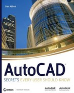
BATTMAN has a feature that people sometimes overlook. The Sync button allows you to apply changes to attributes contained within existing block definitions to all current insertions of those blocks. It also displays conflicting attribute names in red, lets you remove attributes from a block, and allows you to change the order in which attributes are displayed and prompted for. See Figure A.1.
This release introduced the variable DIMASSOC and made it possible to place dimensions in Paper Space and have them connect to (sort of) and reflect the actual size of (sort of) objects in Model Space. As a result, some people now routinely place dimensions in Paper Space. The existence of the CHSPACE Express Tool makes it easy to move objects from one space to the other while maintaining their relative sizes. So, where you place dimensions isn't as important as where they end up.
Because the link between Paper Space dimensions and Model Space entities is sometimes tenuous, two new commands were also added: DIMREGEN and DIMREASSOCIATE. Panning with a wheel mouse in a floating viewport leaves the dimensions behind. Typing DIMREGEN usually reconnects them. To force a dimension in Paper Space to be associated with geometry in Model Space, use the DIMREASSOCIATE command, and follow the prompts. This is not the same command as DIMREASSOC, which is a useful Express Tool that has nothing to do with Paper Space.
I mentioned the DIMASSOC variable earlier. Pre-AutoCAD 2002 drawings used the variable DIMASO to control dimension associativity, which meant something different than it does now. DIMASO has two settings: 0 and 1 (on or off). If it's set to 1, dimensions are blocks associated with definition points (points placed on the DEFPOINTS layer). If DIMASO is set to 0, dimensions are inserted as exploded blocks.
The variable DIMASSOC has three settings: 0, 1, and 2. The 0 and 1 settings behave the same way they do for DIMASO. Only a setting of 2 lets you place a dimension in Paper Space and have it automatically give you the correct distance in Model Space. And, only a value of 2 connects the dimensions with the objects so that moving an object causes the dimension to move with it.
When you open an older drawing, its DIMASO value is used as the setting for DIMASSOC. A pre-2002 drawing therefore won't have the new kind of associative dimensions.
The Standards Manager allows a CAD manager, or any user, to create a template drawing with standard layer names, dimensions styles, linetypes, and text styles. This is easily done by setting up a drawing that meets office standards in those areas and saving it with a .dws extension using the AutoCAD Save Drawing As dialog box, or by renaming an existing DWG file. Once a standards file has been created, it can be used to check how well any drawing adheres to that standard.
Digital signatures are verified with a digital ID that you install on a specific workstation after registering with (and paying) an online verification service like Verisign. This allows you to "sign" a drawing file as assurance to someone who gets it that it's authentic, and makes you responsible for the contents of that file. A seal and signature would be used for that purpose on a paper drawing. Digital signatures aren't widely used, in my experience—many CAD managers turn them off. But this feature is useful to some people.
Password protection is another security feature. If I were a CAD manager, I'd disable this feature when I installed AutoCAD on workstations. It allows a user to add a password to a specific drawing file so that it can't be opened by anyone who doesn't know the password. This is effective and difficult to defeat. The problem from a CAD manager's point of view is the possibility that someone will encrypt a drawing in this way, either accidentally or maliciously, and then no longer remember, or be willing to give you, the password.
As an IT manager, either CAD or otherwise, you want to maintain your systems in a "hit-by-a-bus" manner. If a key person is unavailable for any unforeseen reason, you want to be able to continue to get work done. So be warned: I recommend automatic backups of all drawings to a secure network location and the use of password protection only when necessary. I usually recommend against all password-protection of drawings.
Markups can be added to DWF files with Autodesk Design Review. As of AutoCAD 2002, AutoCAD can work with markup data from those programs.
AutoCAD 2002 included tools for aiding in the upgrade process by automatically converting menus, aliases, and certain software settings. Some of those tools are still included with new AutoCAD releases, but others (including ScriptPro) must now be downloaded from the Autodesk website.
Nearly two years after Release 2002, Release 2004 arrived in March 2003. There was some speculation that Autodesk was avoiding the curse of the odd-numbered release by giving this release a name that was a good eight months early. This was the first of the new releases with a new file format. Tool palettes and license borrowing were my personal favorite features in this release, but it included a few other things as well.
Once again, the file format changed, and it remained the same through AutoCAD 2006. It changed again in AutoCAD 2007; reportedly that format will stay the same through the next two releases. One complaint about AutoCAD 2004 was the elimination of the ability to save a file in R14 format. For those working with many other offices, that became a major problem; it was often solved by retaining a license for AutoCAD 2002 or purchasing IntelliCAD, which can save to all earlier releases. As of AutoCAD 2007, you can save a file back to R14.
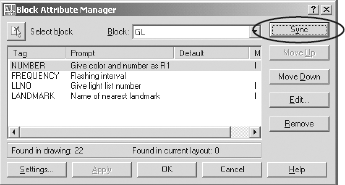
This command lets you edit external references directly within a host drawing without opening them. It allows you to edit both XRefs and blocks, creating problems for people who double-click them by mistake—to exit the REFEDIT command, you must click the Close button in the REFEDIT tool bar, which is not the same as the Cancel button. It's a quick way to edit a block, but you can't change the insertion point this way. If you get the message that objects are "not in the working set," you're stuck in REFEDIT mode and need to use REFCLOSE to cancel it or open the REFEDIT toolbar and click the button shown. See Figure A.2.
Note
To prevent people from editing a drawing file when it's used as an external reference, set the variable XEDIT to 0 in that drawing before saving it.
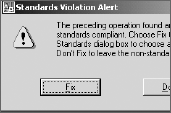
Tool palettes were one of the most useful enhancements to AutoCAD 2004, and they have gotten better since. Tool palettes have windows that contain images of block definitions, which may be saved either in the current drawing or in a different drawing, like a symbol library. (See Figure A.3).
Tool palettes offer three main advantages over using an image pull-down menu to manage block libraries:
It's easy to set up a tool palette, in contrast to the task of editing a long, complex
ACAD.mnsfile, which requires the creation of a slide for each block definition. With tool palettes, you can place a definition on the palette, and it automatically creates an image.Block definitions don't need to be in the current drawing or saved as separate files to be inserted from outside the drawing, because individual block definitions within a saved drawing can be referenced on the palette. In later releases, ADC can be used to place all block definitions contained in a drawing directly onto their own palette.
You can set the properties of each item on the palette to use a specific layer, scale, or rotation, which is helpful in encouraging users to maintain office standards. Block definitions on the tool palette don't take up any space in the current drawing until a block is inserted. Otherwise the definitions sit inside an existing saved drawing on a drive or website.
Note
See Chapter 3, "Customizing AutoCAD's Interface," for information on creating and controlling tool palettes.
A DC Online tab was added to AutoCAD DesignCenter to allow content to be inserted from a website directly into a drawing. Autodesk now has a large symbol library available through this tab, although it's a bit cumbersome to use.
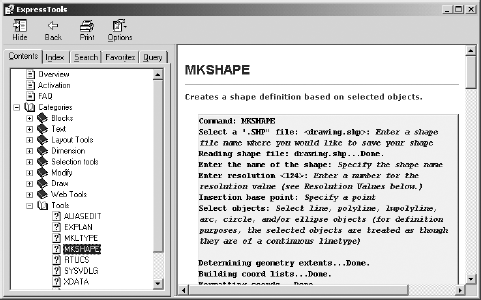
What were called Bonus Tools in R14 became Express Tools in AutoCAD 2000 and had to be downloaded from Autodesk. Unfortunately, Autodesk decided to charge $120 for them in AutoCAD 2002 (except for VIP subscribers), which caused a very strong reaction. AutoCAD 2004 marked their return as part of the $3,700 price of AutoCAD. They haven't been entirely updated since, but they're still available and much loved by users. You should review each tool so you know what it does. That may prevent you from wasting time searching for a solution to a problem can be solved with one of these great tools. I've been asked by users how to place text along an arc, explode text, flatten a 3D drawing, and perform many other tasks that can be done using an Express Tool.
The Express Tools appear in the Express pull-down menu or on their own toolbars, and have a good Help system of their own. (See Figure A.4.) If they don't appear on your computer, type EXPRESSTOOLS or EXPRESSMENU and see if a menu appears. If it doesn't, the Express Tools weren't installed when AutoCAD was installed. If you're the person who loaded the software, get out the CDs, and install them now. If someone else is that person, beg to have the Express Tools installed (actually, make a case for efficiency, because it's an easy case to make). I expect future releases to include even more Express Tools as native commands.
Because I don't use gradient effects, I didn't see this feature as a big deal. However, a lot of people use gradient effects as a shading technique (particularly architects showing elevations). They're a form of a hatch pattern that varies in color shading over its area.
This is another feature that didn't seem important until I heard from people who use it. Those who use AutoCAD for interior design and other color-dependent disciplines can match colors to an industry standard using color books. This means that color-selection dialog boxes now have three options:
Index—The standard 256 colors that AutoCAD has always had
True Color—A mixing area where a user can define colors by mixing red, blue, and green
Color Books—Lets you select from predefined colors published in the U.S., Germany, and Japan as DIC, Pantone, and RAL color books.
Open the Communication Center dialog box by selecting the small dish icon in the lower-right corner of the screen. You can use it to check for updates to AutoCAD. If you have a live web link, you can set this feature to check daily for new updates, and then you'll be notified of service packs (all current releases have at least one) and other updates. Content is also available for disciplines you can specify.
To change settings, right-click the icon, and make the selections you want. You must select the country you're in for any settings to take effect.
Note
I set the Communication Center to notify me about updates only when I ask it to (On Demand). This service can cause problems when it's set to automatically check for existing updates, particularly in a network environment. I often have to shut down the service manually in order to get AutoCAD to close, and having it open can sometimes interfere with the license-acquisition process required for AutoCAD 2006.
The PUBLISH command was enhanced in this release to allow the creation of a multisheet DWF file. Layouts from different drawings are selected and added to a list, plotter information is added, and a single file can then be transmitted to others who have software that can view DWF file, even if they don't have AutoCAD.
In AutoCAD 2004, it was finally possible to plot a rendered or shaded 3D image to a raster plotter.
This new kind of help screen was designed to assist users who were upgrading by identifying the new features in the software and providing some instruction on how to use those features. This tool continues to appear in newer releases and makes it easier to get a quick sense of what has been added. You can use it to help you decide whether to upgrade. To do so, download the 30-day trial version of AutoCAD from the Autodesk website, run the New Features Workshop (accessible through the Help pull-down menu), and decide if it's worth the cost of an upgrade.
AutoCAD 2004 introduced a number of changes to the manner in which the software can be installed, the licensing process, and the operating systems supported, some of which you may have overlooked and which may be significant.
Many of us got burned while installing AutoCAD 2002 when we discovered that the person logging in to the workstation must be a Power User in Windows in order to use AutoCAD. This limitation has been removed. The software can now be installed in such a way that anyone can use it. I have no idea what the intent of that limitation was, but getting rid of it was welcome.
This release won't run on Windows 98 or Windows 95. It's optimized for Windows XP, although it also works just as well in Windows 2000.
The most interesting and useful licensing feature is the appearance of a network license-borrowing option. If your office is using a network license that is limited to a specified number of users at one time, it's possible to borrow a license and use that license on a workstation that isn't even connected to the network. Now designers can work all the time by taking their work home with them! That may be good or bad, but it eliminated a frustrating problem in some offices. To borrow the license, use the Help pull-down menu in this release.
Autodesk finally hit a 12-month release cycle when AutoCAD 2005 showed up exactly 12 months after the last release in March 2004. The TABLE command was one of the three most significant improvements in Release 2005, in my opinion. The others are fields and sheet sets. To the relief of users everywhere, the file format stayed the same.
Organizing text into a table format has never been easy in AutoCAD, although it's been possible to import Access and Excel files as OLE objects since R14. Now, however, AutoCAD includes table objects that can be edited while retaining their format, and that contain data—either text data or fields. Fields are the most interesting of the data types, particular as of AutoCAD 2006, which allows equations to be entered into cells in the table. A table can also be exported to a comma-delimited text file (a CVS file), which can be read by database and spreadsheet software.
Here are a few recommendations about tables:
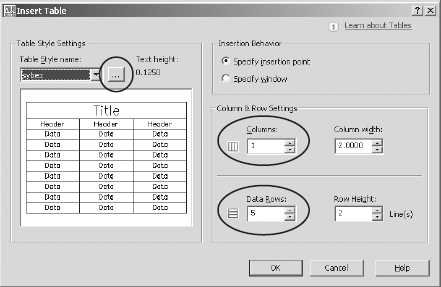
Create a new table style (click the ellipses button) that uses a proper font for all three table items: Data, Column Heads, and Title.
Use text heights that meet your office standards.
Assign a name other than Standard. (See Figure A.5.)
To enter a field into a table cell, double-click in the cell to open the MTEXT editor. Now, right-click to bring up the MTEXT menu, and select Insert Field. To edit a table cell, double-click its contents. To edit a table itself (column sizes, and so on), select the table, right-click to bring up the context-sensitive menu for tables, and select Properties. You can use the Properties palette to change the structure of the table. To delete a row or column, right-click in a cell, and select Delete Row or Delete Column.
Fields are potentially useful and powerful tools. They can be variable, in the sense that values in fields can be made to change automatically. A date field, for example, always contains the current date (although a REGEN may be necessary to match the display to the value). A system variable field always contains the current setting of that variable. Fields are also customizable using the following drawing properties and Diesel expressions:
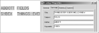
You can create drawing properties (title, author, comments, keywords or custom) from the File pull-down menu. Once you've defined custom properties, they're listed by the names you gave them in the list of possible fields. Change the properties, and they change in the field location (either in a table or anywhere else). (See Figure A.6.)
You can also use Diesel expressions in fields. This opens up many possibilities, because Diesel is a restricted programming language. Although it's used primarily for menus, you can use it to create equations. AutoCAD 2006 added spreadsheet-like equations to tables, and so many existing fields are identified that it's unlikely you'll need to use Diesel. But now you know it's there.
Many of the fields are obvious: date of creation, which doesn't change; date, which does change; time; and so on; but some aren't so obvious. The listed fields when you right-click in MTEXT and select Insert Field include the following, plus any custom drawing properties you create. The asterisk is used here as a wildcard:
Author (dwg property) | |
Comments (dwg property) | Login |
CreateDate | NamedObject |
CurrentSheet* | Object |
Date | PageSetupName |
DeviceName | PaperSize |
Diesel Expression | Plot* |
Filename | SaveDate |
Filesize | Sheet* |
Hyperlink* | Subject |
Keywords (dwg property) | SystemVariable |
LastSavedBy | Title (dwg property) |
Note
Don't overlook the SystemVariable field, which gives you access to 500 or so variables. The Filename field gives both the default path and the name of the current drawing. For just the filename without the path, place the variable DWGNAME as a SystemVariable field. For a list of all system variables, type SETVAR
A new layer-management feature was added in AutoCAD 2005. In addition to being able to save layer states and create filters for listing layers based on common properties, you can group layers. This caused some confusion, because layer filters create groups. However, there's a difference that makes this feature extremely valuable.
A layer filter lists layers based on properties that are common to those layers. They're all turned off, for example, or they all contain some of the same characters in their name. Layer grouping, on the other hand, allows you to create a layer group that contains layers with no common characteristics—you just want to control them all at the same time.
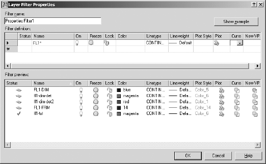
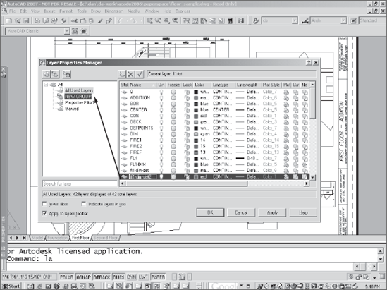
To create a layer filter, open the Layer Manager, place the cursor in the left window, right-click, and select New Properties Filter. In the window that opens, you can identify the common characteristics you want to use to filter a layer list.
Figure A.7 shows the use of the asterisk wildcard to filter all layers beginning with the characters FL1 and ending in anything. The Freeze column filters out frozen layers. The resulting list is shown at the bottom. When you select this filter, the layer list window shows only the layers that meet these two criteria.
To create a layer group, open the Layer Manager, place the cursor in the left window, right-click, and select New Group. Now, select All at the top of the tree in the left pane. You can drag-and-drop any layer onto the new group, as shown in Figure A.8.
Several new productivity tools appeared in AutoCAD 2005. Whether you think they increase your productivity may depend on how you intend to use them.
When you double-click the edge of a floating viewport in a layout, the viewport is maximized, and you can work in a facsimile of the Model Space tab. When you click the Maximize Viewport button at the bottom of the screen, it takes you back to the layout in the same state you left it in. I liked this idea when I first read about it, but it has one huge limitation: The maximized viewport doesn't honor the zoom magnification of the viewport when you place dimensions. That makes it unusable, to me.
Note
Use VPMAX only for editing geometry, not for adding or updating dimensions. If your dimension style is designed to scale dimensions to the layout, the size of dimensions will vary with the zoom you're using while in the maximized viewport. Too bad.
This feature is a most welcome new osnap. It allows you to snap halfway between any two points. You can do that and much more with the transparent calculator command ['CAL –> (end + end)/2], but having a dedicated object snap is very nice.
Sheet sets are composed of layouts from a variety of saved drawings. The set can have an index and can be used to open, organize, and plot the set of sheets you select. This is a useful tool for project management and is another under-utilized feature of AutoCAD. Like many AutoCAD features, sheet sets gain more functions with each release. They're complex, but their creation is aided by a wizard-type interface.
Sheet sets can be organized as projects and given tracking numbers, project names, phase-completion data, cross-sheet call-outs, and additional custom properties. As with other file-management tools, you must take care not to change drawing names or locations within projects once layouts are identified as part of a sheet set.
Once you create a sheet set, you can manage it with the Sheet Set Manager palette. You can also use it as the basis for the PUBLISH command to create a DWF file consisting of the entire sheet set, with an index and table of contents. This can be helpful in plotting groups of drawing for transmittal to a client.
Note
Sheet sets haven't caught on as quickly as I expected, probably because they have so many options. Don't be intimidated by sheet sets. Despite the large number of new commands associated with this feature, and the potential complexity, the Sheet Set Wizard makes it easy to get started.
Release 2006 came out in March 2005, right on schedule. One fundamental AutoCAD feature was dramatically enhanced in this release: Blocks became dynamic. At least, they can become dynamic. This is also the release when Autodesk finally bowed to the building pressure to modernize the AutoCAD interface by eliminating the command line. That's what a lot of people wanted, anyway, and Autodesk did it right by making the command line, like other interface tools, optional.
People often want to change a block after it's inserted. They'd like to move an element within the block, stretch the block, rotate something within the block, and so on. In the past, doing so required redefining the block or having multiple definitions of the same block. Now, with dynamic blocks, you can make those kinds of changes without redefining a block definition. But—the changes have to be anticipated when the block is defined. That's the hard part.
The block definitions in AutoCAD 2006 aren't an alternative to the block definitions we all know and love. They're enhancements of standard blocks. They allow a block to be defined in more than one state, so that as it's inserted, the appropriate variation can be used for each instance. The most common example for explaining dynamic blocks is a door symbol. It can be defined as a single block definition with different states for size, right or left swing, how many degrees it can open, different insertion points, or anything else. It's possible to define block states for a single definition that have no logical relationship to each other. You could have a definition that in one state represents a car and in another state represents a banana. You wouldn't, but you could.
Because the new dynamic characteristics are more difficult to define, AutoCAD 2006 includes a new block definition space. We can almost say that there are three spaces: Model Space, Paper Space, and block-editing space.
Note
I don't recommend spending time creating dynamic replacements for all your current symbols. If your current system for managing symbols works well, continue to use it. When you find that a dynamic version of a symbol would offer advantages, add those parameters and actions to existing block definitions.
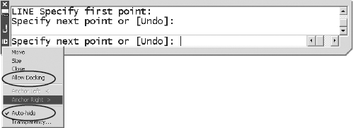
A button on the bottom on the status bar turns dynamic input on or off. If it's on, you see command-line information at the cursor as you work. If you like this kind of control for some situations but not for others, you can toggle the command line with the Ctrl-9 combination or use COMMANDLINEHIDE for off and COMMANDLINE for on. You can also auto-hide the command line the same way you can auto-hide a tool palette. (See Figure A.9.)
With all the options for controlling dynamic input, what should you do? Experiment a little. I like setting dynamic input so that Pointer Input is on but Dimension Input is off. That reduces the clutter around the cursor. Then, I set the command line to auto-hide so it's out of the way. If I want it, I hover over the title bar. When I'm programming, I always turn DYN off so I can use the command line to test code.
Note
By default, any coordinates entered in AutoCAD's new Dynamic Input window are relative, not absolute. This makes sense for most people, because relative coordinates are used far more often than absolute. If you want to enter absolute coordinates, precede them with the pound sign (#4,3). If you want to go back to the behavior of earlier releases, change the value of DYNPICOORDS to 1.
Several dimension enhancements appeared in AutoCAD 2006:
Arrowhead flipping—You can select a dimension, right-click, and select Flip Arrow to get it inside or outside when you don't like its location.
Jogged radiuses—If you have a long radius and want to create a traditional jog in the dimension line to reduce its length, you can now do so. You can even control where the jog occurs, using grips. I wish ordinate dimension doglegs could be edited the same way. Maybe next time.
Arc length—An arc length symbol is now available for arc length dimensions. The default location isn't standard. Change it to Above in the Dimension Style dialog box.
Fixed-length extension lines—If you want to force all dimension lines to be a fixed length, you can now do that.
The hatch command got a much-needed update in this release. It's finally possible to get a hatch pattern to start at a particular location without changing the UCS, for one thing, but my favorite change is the ability to create separate hatches at one time:
Hatch origin A Hatch Origin button in the Hatch dialog box lets you pick a starting point for a hatch pattern. It's helpful in placing user-defined hatches for clapboard siding (line it up with the top of the windows) or brick patterns.
Note
If you have an earlier release, it's still possible to change the hatch origin, because it's based on the 0,0,0 location of the current coordinate system. Before placing a hatch pattern, relocate the UCS origin to the coordinates you want as the hatch origin. After placing the hatch, change them back.
Hatch area You can select a hatch pattern as an object in the AREA command.
Hatch boundary re-creation If you happen to erase a boundary used to create a hatch pattern and want it back, you can re-create the boundary using the Hatch Edit dialog box.
Separate hatches If you want to create separate hatches in one operation by selecting several points, you can specify that in the Hatch dialog box.
This is a welcome and valuable enhancement to the CAL command. Many people overlooked the CAL command because it was a little tricky to use and had no graphic interface. CAL is a geometric calculator that allows you to do transparent calculations (by typing 'CAL at the command line) using real numbers or geometric values, via osnaps. The result can be used within the current AutoCAD command. Before M2P was added as an osnap, it was common to use the 'CAL command function MEE (midway between two endpoints) or (qua+qua)/2 (midway between two quadrants). Any object snap could be used.
Note
The CAL command can be used to convert between units using the following syntax: cvunit(25.4,mm,inch) or cvunit(10,gal,liter). This is similar to the AutoLISP CVUNIT function, but the Lisp syntax is as follows:(cvunit 1 "mm" "in").
QuickCalc can be executed in one of two ways: You can open it before you start a command, or you can use ′QuickCalc to open it transparently.
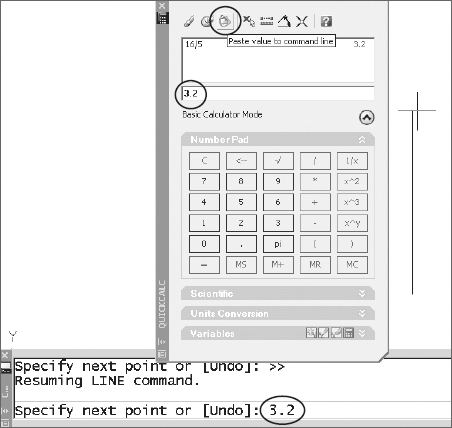
To use it before you start a command, follow these steps (see Figure A.10):
Type
QCto open the QuickCalc palette.Start a line with a polar track set to a logical value.
Click the QuickCalc tool palette, and enter the expression you want (you can use the keypad).
Click the Paste Value To Command Line button.
Select a point in the command line to return to the drawing editor.
Move the cursor to a desired polar-tracking angle.
Press

When you open QuickCalc transparently, it's in Active Command mode and has no Paste Value To Command Line button. Instead, it has an Apply button at the bottom that does the same thing. You don't have to switch from the active palette back to the drawing editor when you use the Apply button.
Converting units is much easier with QuickCalc than with CAL or the AutoLISP CVUNIT function, if your conversion happens to be listed. Open the Units Conversion pane in the QuickCalc palette, and you can see a list of various units grouped by type. If you're converting from feet to miles, for example, find the units under Length, make the conversion, and then use the result as input for further calculations. (See Figure A.11.)
There are some surprising omissions. Gallons aren't listed under volume, so calculations that allow tank sizing can't be done directly. For that, use the CVUNIT function.
To see the list of conversion units available for use with the CVUNIT function for either AutoLISP or the CAL command (but not for QUICKCALC), open the ACAD.unt file. Type (startapp "notepad" (findfile "acad.unt")) to open it directly from the AutoCAD command prompt. If you change this file and want to save it, you must first close AutoCAD—the file is loaded when AutoCAD starts, and there is no way to reload it. ACAD.unt is located in the following folder (replace %username% with the logon name of the current user in the following path):
C:Documents and Settings%username%Application
DataAutodeskAutoCAD 2006R16.2enusupportacad.unt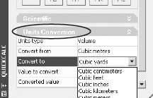
This file contains a stunning number of conversions, but you can add any that are missing by following the format used by all the others. This is an interesting file, defining units as either fundamental (based on several constants) or derived (based on a defined unit).
The following examples of unit definitions from the ACAD.UNT file show
A fundamental definition for one meter, with alternate spellings
An existing derived unit (feet from meters)
A user-defined unit (paces, which is my own admittedly nonprecise addition) based on 2.3 feet
Here's the code:
; Basic SI units
*meter(s),metre(s),m
−1,0,1,0,−1,4.1214856408e11,0
*f(oot.eet),ft,'
=meter 0.3048
*Pace(s),pc(s)
=foot 2.3
If you add Pace(s) as shown and save the file, you can now use the CVUNIT function of either the CAL command or AutoLISP to convert from any linear distance to paces. Convert one mile into paces by typing (cvunit 1 "mile" "paces") at the command line. The resulting conversion is 2295.65 paces per statute mile, just so you know what you're getting into the next time you decide to walk a mile.
Tables in AutoCAD 2006 got a big boost with the ability to place formulas in individual cells that can reference other cells, much like a spreadsheet can. The columns in a table are identified alphabetically, the rows numerically. However, unlike in an actual spreadsheet, the letters and numbers used to identify each cell aren't shown—they're implied.
Note
See Chapter 5 for a more complete discussion of tables.
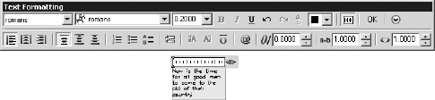
The MTEXT editor keeps getting enhanced. In this release, the kind of numbering and bulleting functions that word processors have were added to the greater justification control and symbol library introduced in earlier releases. This in-place editor always displays text at its actual size and in its actual location. This means you often get effects like those shown, where the small size of the text makes editing difficult. (See Figure A.12.)
The good news is that your wheel mouse lets you zoom the text while you're editing it. Because the toolbar isn't connected to the editor directly, you can float it to any useful location.
Note
The WYSIWYG behavior of the MTEXT editor is a problem if you're adding text at any angle other than zero. It shows up in true position in the editor, forcing you to twist your head. So, it's possible that you won't like the new editor. If not, the old editor is still available by setting the MTEXTED variable to "oldeditor" instead of "internal" If you want to, you can use both and go back and forth. You may want the old behavior for adding information to vertical title blocks but the new behavior for adding notes.
This is now an in-place editor, which has the same problem with angled text that the MTEXT editor does. It also eliminates the option of selecting new starting points for additional single lines of text while still in the command. Some people don't like that, so they change the value of DTEXTED from 0 to 1 to get the old version. I don't think the new version adds enough to overcome its deficits in AutoCAD 2006; but in AutoCAD 2007, a third setting was added to DTEXTED that lets you have both in-place editing and the ability to select multiple starting points.
Note
I was presenting to a group of users recently and found that most of them didn't realize you ever could place single lines of text in multiple locations by selecting new points. It's nice for filling in title blocks and forms, but running osnaps work only for the first selection.
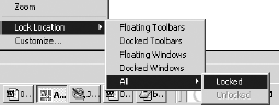
I sometimes move a window, palette, or toolbar by accident as I'm drawing. I get going a little too fast, and suddenly I've ripped a toolbar away from the location where I'd like it to stay. As of AutoCAD 2006, you can lock the locations of toolbars and windows (including palettes and the command window). I love this feature, minor though it may be. Just right-click any open toolbar (but not palette), and select Lock Location (the next-to-last item in the list). In Figure A.13, all four types of items are locked. To move them, you must first unlock them.
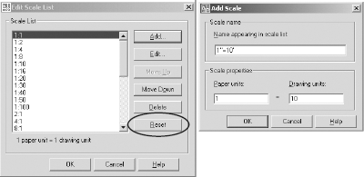
You can finally use SCALELISTEDIT if a scale you use is missing from the standard list. You can also delete the scales you don't use at all. If you delete them and later regret it, you can get them back using the Reset button.
In Figure A.14, I've added an engineering scale by giving it the name that would appear in a title block and assigning the scale factor to be used for drawings where decimal feet is the base unit (common for civil engineering).
There have been a number of command enhancements, including adding an Undo option to several commands that didn't have it previously. You may want to be aware of two new options in the RECTANG command: area and rotation. Area is interesting and probably responds to the wishes of a small number of users. If you select this option, you're prompted for an area and then either a length or width, after which the other dimension is calculated.
A brand-new command appeared in AutoCAD 2006. It allows you to join multiple line segments, arcs, elliptical arcs, splines, and polylines to themselves (as in closing an elliptical fragment) or to each other. The segments can be separated, can touch, or can overlap.
Note
One drawback to JOIN is that many users have defined a command with the name Join, using AutoLISP, for joining lines into plines using the PEDIT command. If you have a custom Join command, it won't work until you rename it. You can UNDEFINE the AutoCAD JOIN command so you can use yours, but I'm reluctant to undefine native commands.
Finally, someone noticed that the most common use of the FILLET command is to close up lines with sharp corners and that it's common to do this multiple times. I love these new functions:
Shift for 0 radius The best minor enhancement to AutoCAD 2006 may be the use of the Shift key to create a fillet or chamfer with a radius or distance of 0 for use when cleaning up corners. This is my most common use of the FILLET command, so it's nice that an override of 0 can be applied this way.
MULTIPLE Once you select the Multiple option, you can make both of these commands persistent. You could do that in the past by typing MULTIPLE before starting the FILLET or CHAMFER command, but now you get this option while in the command, even if you forgot.
These commands now have a Copy option. You can still use grips, as always, to copy/rotate or scale/rotate at the same time, but this is a logical improvement.
At long last, you can use a crossing window to select multiple objects to extend or trim. This could only be done with a fence selection in the past.
You can now build a selection set for STRETCH with multiple selections without having to use the MSTRETCH Express Tool.
The AutoCAD menu structure has been completely overhauled to provide a more intuitive means of customizing the interface. The CUI command loads an environment in which HTML files with a .cui extension can be edited. This replaces the menu files of the past. Some things still can't be customized with the CUI, but I think it will eventually become the means of doing all interface customization.
Note
See Chapter 3 for a more complete discussion of customizing using the CUI.
The workspace concept is new as of AutoCAD 2006. At first, workspaces may seem similar to profiles, but they're different and generally unrelated. Workspaces don't control profiles, even though the Help system implies that they do, and profiles don't control workspaces. See chapter 2, "Managing Your System," for more information about workspaces.
Once again, the next release came 12 months later, in March 2006. I'm guessing we'll see something new in March 2007, too. The big news from AutoCAD 2007 is a new 3D engine that has some similarities with VIZ, with vastly improved rendering capabilities and some new 3D functions, including lofting, helixes, and an automatically changing UCS. Those features are dealt with in chapter 7, "AutoCAD Scripts."
In all, AutoCAD 2007 provides nearly 80 new commands, more than 65 changed commands, and nearly 100 new or changed system variables. There are a few new things you should be particularly aware of.
External reference management has a new tool palette similar to ADC, the External Refernces palette. It includes images as well as DWG files. When you use it and can't find the functions you need, just right-click, and they will be listed.
A handful of dimensioning enhancements allow you to fine-tune your dimension styles. They aren't necessary for most users, but there are now dimension style variables that control the linetypes used for extension lines and dimension lines, so it's easier to create proper dimensions to centerlines, for instance. You can also add a background mask to dimension text to make the text more readable when applied to areas with a lot of detail.
CHSPACE, the indispensable tool for moving entities between Paper Space and Model Space, has been integrated into AutoCAD as a command, along with many of the wonderful layer-management tools.
A series of new workspaces and visual styles are now controlled by a Dashboard palette and used for different kinds of modeling:
Classic AutoCAD 2D
3D conceptual, which is similar to Inventor in appearance
3D rendering
Model viewing
Note
An unofficial history of AutoCAD is available at http://betaprograms.autodesk.com/history/autocad_release_history.htm if you're interested in such things. You'll be stunned by how many changes have been made in each release.
Autodesk has made one thing clear about future releases of AutoCAD: Despite the large number of changes that are coming, the current user interface will remain accessible, and nothing will be done that might discourage long-time users from continuing to use AutoCAD. The command line will be optional, but it will remain.
At the same time, AutoCAD will probably get more and more like Inventor, VIZ, and Revit in some ways. Because the upgrade cycle is now firmly entrenched at 12 months, those changes are likely to appear quickly over the next few years.
Commit yourself to life-long learning if you want to work in any design field that employs CAD software—even if that seems sometimes like a blessing and sometimes like a curse.