
6.3 MPEG Surround encoder
6.3.1 Structure
The structure of the MPEG Surround encoder is shown in Figure 6.4. A multi-channel input signal is first processed by a channel-dependent pre-gain. These gains enable adjustment of the level of certain channels (for example LFE and surround) within the transmitted down mix. Subsequently, the input signals are decomposed into time/frequency tiles using an analysis filter bank. A spatial encoder generates a down-mix signal and (encoded) spatial parameters for each time/frequency tile. These parameters are quantized and encoded into a parameter bitstream by a parameter encoder (Q). The down-mix is converted to the time domain using a synthesis filterbank. Finally, a post-gain is applied to control the overall signal level of the down-mix.
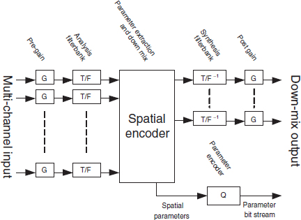
Figure 6.4 Structure of the MPEG Surround encoder. Reproduced by permission of the Audio Engineering Society, Inc, New York, USA.
6.3.2 Pre- and post-gains
In the process of down-mixing a multi-channel signal to a stereo signal, it is often desirable to have unequal weights for the different input channels. For example, the surround channels are often attenuated by 3 dB prior to the actual down-mix process. MPEG Surround supports user-controllable pre-gains between 0 and −6 dB, in steps of 1.5 dB. For the LFE, these weights are adjustable between 0 and −20 dB in steps of 5 dB.
The level of the generated down-mix can also be controlled using (post-encoder) gains to prevent clipping in the digital signal domain. The down-mix can be attenuated between 0 and −12 dB in steps of 1.5 dB.
The applied pre- and post-gain factors are signaled in the MPEG Surround bitstream to enable their inverse scaling at the decoder side.
6.3.3 Time–frequency decomposition
Filterbank
The applied filter bank is a hybrid complex-modulated quadrature mirror filterbank (QMF) that has the same structure as the filterbank applied in Parametric Stereo (see Chapter 5). Table 6.1 gives the number of sub-sub-bands M1(m0) as a function of the QMF band m0 that are used for MPEG Surround.
Table 6.1 Specification of M1 and the resulting number of output channels for the first 3 QMF sub-bands.
| QMF sub-band (m0) | M1(m0) |
| 0 | 8 |
| 1 | 4 |
| 2 | 4 |
The resulting sub-sub-band signals are grouped into so-called parameter bands which share common spatial parameters. Each parameter band comprises one or a set of adjacent sub-sub-bands to form the corresponding time/frequency tiles for which spatial parameters are estimated. For the highest frequency resolution supported by MPEG Surround, the number of parameter bands amounts to 28. Bitrate/quality trade-offs are supported by coarser frequency resolutions, resulting in different combinations of sub-sub-band signals into respective parameter bands. The following alternative number of parameter bands are supported: 4, 5, 7, 10, 14, and 20.
The sub-band signals are split into (time) segments in a similar way as described for Parametric Stereo (cf. Chapter 5) using dynamic segmentation that is adapted to the input signals.
6.3.4 Spatial encoder
Tree structures
The elementary building blocks (as described in Section 6.2.2) are combined to form a spatial coding tree. Depending on the number of (desired) input and output channels, and additional features that are employed, different tree structures may be constructed. The most common tree structures for 5.1-channel input will be outlined below. First, two tree structures for a mono down mix will be described, followed by the preferred tree structure for a stereo down-mix.
The first tree structure supports a mono down-mix and is outlined in the left panel of Figure 6.5. The six input channels, left front, right front, left surround, right surround, center and low-frequency enhancement, labeled lf, rf, ls, rs, c and LFE, respectively, are combined pairwise using encoding blocks (TTO type) until a mono down-mix is obtained. Each TTO block produces a set of parameters P. As a first step, the two front channels (lf, rf) are combined into an TTO encoding block E3, resulting in parameters P3. Similarly, the pairs c, LFE and ls, rs are combined by TTO encoding block E4 and E2, respectively. Subsequently, the combination of lf, rf on the one hand, and c, LFE on the other hand are combined using TTO encoding block E1 to form a ‘front’ channel f. Finally, this front channel is merged with the common surround channel in encoding block E0 to result in a mono output s.
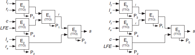
Figure 6.5 Tree configurations for a mono down-mix. Reproduced by permission of the Audio Engineering Society, Inc, New York, USA.
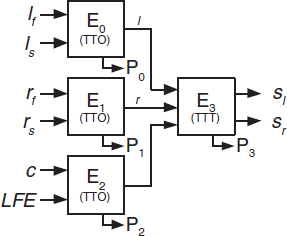
Figure 6.6 Preferred tree configuration for a stereo down-mix. Reproduced by permission of the Audio Engineering Society, Inc, New York, USA.
One of the advantages of this structure is its support for configurations with only one surround channel. In that case, ls and rs are identical and hence the corresponding TTO block can be omitted (i.e., the tree can be pruned).
The second tree structure for 5.1 input combined with a mono down mix is shown in the right panel of Figure 6.5. In this configuration, the lf and the ls channel are first combined into a common left channel (l) using an TTO encoding block E3. The same process is repeated for the rf and the rs channel (E4). The resulting common left and the common right channels are then combined in E1, and finally merged (E0) with the combination of the center and LFE channel (E2). The advantage of this scheme is that a front-only channel configuration (i.e., only comprising l, r and c) is simply obtained by pruning the tree.
For a stereo down-mix, the preferred tree configuration is given in Figure 6.6. As for the second mono-based tree, this tree also starts by generation of common left and right channels, and a combined center/LFE channel. These three signals are combined into a stereo output signal sl,sr using a TTT encoding block (E3).
TTO encoding block
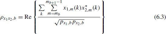
The TTO encoding block transforms two input channels x1,m,x2,m into one mono output channel s1,m plus spatial parameters. Its concept is identical to a parametric stereo encoder (see [47, 79, 214, 217, 234, 235]). For each parameter band, two spatial parameters are extracted. The first comprises the ICLD (ΔLx1x2,b) between the two input channels for each parameter band b:
![]()
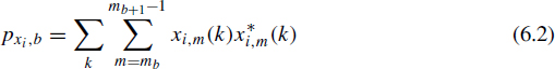
with pxi,b the power of signal xi in parameter band b:
where mb represents the hybrid start band of parameter band b (sub-sub-band sample index) and k the time slot of the windowed segment. The second parameter is the interchannel correlation (ρx1x2,b):
The mono down-mix s1,m comprises a linear combination of the two input signals. The associated down-mix weights for each input channel are determined based on the following decomposition of the two input signals:
![]()
![]()
Hence, the two input signals are described by a common component s1,m which may have a different contribution to x1,m and x2,m (represented by the coefficients ψi,b), and an out-of-phase component d1,m which is, except for the sign, identical in both channels. Furthermore, energy preservation is imposed by demanding the signal s1,m to have an energy that is equal to the sum of the energies of both input signals. The signal s1,m, the desired mono down-mix signal, is given by:
![]()
The energy preservation constraint results in:

The signal d1,m is the residual signal. This signal is either discarded at the encoder side (in the case of a fully parametric description of the input signals, where synthetic residual signals are used at the decoder side) or can be transmitted to enable full waveform reconstruction at the decoder side. A hybrid approach is also facilitated: a specified low-frequency part of the residual signals can be selected for transmission, while for the remaining signal bandwidth, the residual signals are substituted by synthetic signals at the decoder. This option makes the system very flexible in terms of quality/bitrate trade-offs.
TTT encoding block using prediction mode
The TTT encoding block has three inputs (xl,xr,xc), two down-mix outputs (sl,sr) and an auxiliary signal (sc). The two outputs and the auxiliary signal form a linear combination of the input signals according to:
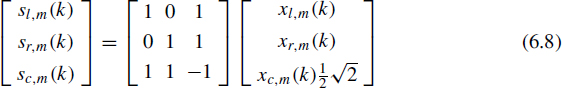
The center signal xc is attenuated by 3 dB to ensure preservation of the center-channel power in the down-mix. The auxiliary output signal, sc, which has orthogonal down-mix weights, would in principle allow full reconstruction of the three input signals by applying the inverse of the down-mix matrix as up-mix matrix. This would result in:
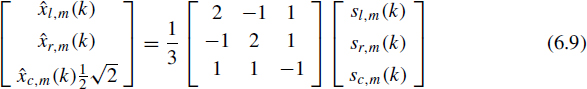
However, this third signal sc is discarded at the encoder side and replaced by two prediction coefficients that enable an estimation ŝc from the two down-mix channels sl,sr:
![]()
with γ1,b,γ2,b two channel prediction coefficients (CPCs) for each parameter band b. The prediction error d1,m
![]()
may be either transmitted or discarded, depending on the desired quality/bitrate trade-off. If the residual signal d1,m is discarded, the corresponding energy loss is described by an ICC parameter ρb:

This ICC parameter ρ describes the ratio between the sum of the energies of the reconstructed ![]() l,
l,![]() r and
r and ![]() c signals using the prediction ŝc and the sum of the energies of the original input signals:
c signals using the prediction ŝc and the sum of the energies of the original input signals:
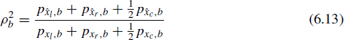
If the prediction error d1,m is zero, the ICC parameter will be exactly +1. Lower values indicate a prediction error (i.e., a prediction loss).
TTT encoding block using energy mode
The predictive mode for the TTT encoding block requires a reliable estimate of the signal sc at the decoder side. If waveform accuracy cannot be guaranteed (for example in the high-frequency range of an audio coder employing SBR), a different TTT encoding mode is supplied which does not rely on specific waveforms, but only describes the relative energy distribution of the three input signals using two ICLD parameters:
![]()
The prediction and energy mode can be used independently in different bands. In that case, parameter bands of a specified (lower) frequency range applies prediction parameters, while the remaining (upper) parameter bands apply the energy mode.
MTX conversion block
Matrixed surround (MTX) refers to a method to create a pseudo surround experience based on a stereo down-mix with specific down-mix properties. In conventional matrixed surround systems, the down-mix (slMTX,srMTX) is created such that signals of the surround channels are down-mixed in anti-phase. The anti-phase relationship of the surround channels in the down-mix enables a matrixed surround decoder to control its front/surround panning. The drawback of this static down-mix matrix is that it is impossible to retrieve the original input channels, nor is it possible to reconstruct a conventional stereo downmix from the matrixed surround compatible down-mix. In MPEG Surround, however, a matrixed surround mode is supplied for compatibility with legacy matrixed surround devices and hence this option must not have any negative impact on any MPEG Surround operation. Therefore, the approach of MPEG Surround to create a matrixed surround compatible down-mix is different from the static down-mix approach of conventional matrixed surround encoders. A conversion from a conventional down-mix to a matrixed surround compatible down-mix is facilitated by a MTX conversion block applied as post-processing stage of the encoding tree.
The MTX conversion block has two inputs and two outputs. The two output signals are linear combinations of the two input signals. The resulting 2 × 2 processing matrix is dynamically varying and depends on the spatial parameters resulting from the spatial encoding process. If the surround channels contain relatively little energy, the two output signals of the MTX processing stage are (almost) identical to the two input signals. If, on the other hand, there is a significant surround activity, the 2 × 2 matrix creates negative crosstalk to signal surround activity to a matrixed surround decoder. The advantage of employing this process on a stereo down mix rather than on the multi-channel input, is that the 2 × 2 processing matrix is invertible. In other words, the MPEG Surround decoder can ‘undo’ the processing by employing the inverse of the encoder matrix. As a result, the matrixed surround compatibility has no negative effect on the 5.1-channel reconstruction of an MPEG Surround decoder.
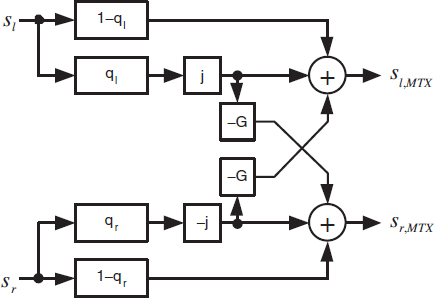
Figure 6.7 Matrixed surround conversion block. Reproduced by permission of the Audio Engineering Society, Inc, New York, USA.
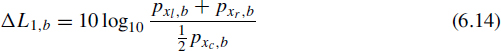
The matrixed surround conversion block is outlined in Figure 6.7. Both the down-mix signals, sl and sr, are split in two parts using parameters qL and qR. These parameters represent the relative amount of surround energy in each parameter band of sl and sr, respectively and are derived from the encoded spatial parameters. For nonzero q, part of the input signal is processed by a 90° phase shifter (indicated by the ‘j’ block). The phaseshifted signal is subsequently mixed out-of-phase to both output channels slMTX,srMTX, including a (fixed) weight G = ![]() for the cross-term.
for the cross-term.
The scheme depicted in Figure 6.7 can be described in matrix notation employing a conversion matrix Vb:

with
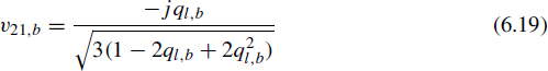
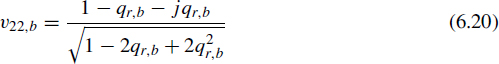
The elements of the conversion matrix V are determined for each parameter band and are dependent on the spatial parameters resulting from the preceding tree:
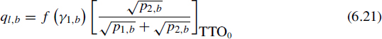
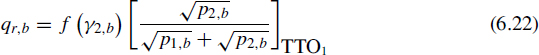
where XTTOi denotes the fraction X of TTO block Ei of Figure 6.6.
External down-mix analysis block
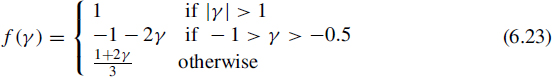
In some cases, the use of an externally provided down-mix may be preferred over an automated down-mix. For example, a studio engineer might produce separate stereo and multi-channel mixes from the same (multi-track) recording. MPEG Surround provides the possibility to transmit such an externally provided down-mix instead of the automated down-mix. In order to minimize potential differences in the resulting multi-channel reconstruction, the external down-mix analysis block parameterizes the differences between the automated and externally provided down-mixes. The external down-mix analysis block is used as a post-processor of the full spatial encoder tree. For each internal, automated down-mix channel si,m and the corresponding externally provided down-mix channel ei,m, the energy ratio within each parameter band is extracted according to:
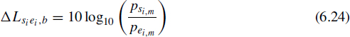
This down-mix gain parameter describes the level adjustment in each parameter band that should be applied to the externally provided down-mix to result in a down-mix that is equal to the automated down-mix from a (statistical) energy point of view. On top of this ICLD parameter, residual signals ei,m can be transmitted for a user-selectable bandwidth to obtain waveform reconstruction of the automated down-mix from the (transmitted) external down-mix:
The parameter η controls the method of coding of the residual signal; η = 0 results in absolute coding of the automated down mix si,m, while for η = 1, the difference between the automated down-mix si,m and the gain-adjusted externally provided down-mix ei,m is used as residual signal. The latter method is especially beneficial if there exists a high correlation between the externally provided down mix and the automated down-mix.
6.3.5 Parameter quantization and coding
Parameter quantization
For ICLD and ICC parameters, the same quantizer is used as applied in parametric stereo coders. The CPC coefficients are quantized linearly with a step size of 0.1 and a range between −2.0 and +3.0.
Further bitrate reduction techniques
The quantizer described in Section 6.3.5 aims at just-inaudible differences in spatial properties. An additional quantization strategy is also supplied based on a reduced number of quantizer steps to reduce the entropy per transmitted spatial parameter. This ‘coarse’ quantization comprises only every even quantizer index of the quantizer described in Section 6.3.5.
If such coarse quantization steps are applied, there is a risk that the relatively large discrete steps in changes in spatial properties give rise to audible artifacts. For example, if a certain sound object in the multi-channel content is slowly moving from one speaker location to another, the smooth movement in the original content may be reproduced at the decoder side as a sequence of discrete positions, each perceived position corresponding to a quantizer value. To resolve such artifacts, the encoder may signal a ‘smoothing flag’ in the bitstream, which signals the decoder to apply a low-pass filter on the discrete parameter values to result in a smooth transition between different quantizer values.
A related technique for further bitrate reduction is referred to as ‘energy-dependent quantization’. This method allows for combinations of fine and coarse parameter quantization, depending on the amount of signal energy within the tree structure. If the amount of signal energy in a certain part of the parameter tree is significantly lower than the overall signal energy, large quantization errors in that specific part are in most cases inaudible, since they will be masked by signal components from other channels. In such cases, a very coarse parameter quantization can be applied for relatively weak channel pairs, while a fine quantization may be applied for strong (loud) channel pairs.
Besides changes in quantizer granularity, MPEG Surround also features the possibility to transmit only a selected number of parameters. More specifically, only a single ICC parameter may be transmitted instead of a separate ICC value for each TTO block. If this single ICC mode is enabled, the same transmitted ICC value is used in each OTT decoding block.
Finally, the resulting quantizer indexes are differentially encoded over time and frequency. Entropy coding is employed on the differential quantizer indexes to exploit further redundancies.
6.3.6 Coding of residual signals
As described in Section 6.3.4, TTO and TTT encoding blocks can generate residual signals. These residual signals can be encoded in a bit-efficient manner and transmitted along with the corresponding down-mix and spatial parameters.
Residual data do not necessarily need to be transmitted since MPEG Surround decoders are capable of reconstructing decorrelated signals with similar properties to those of the residual signals without requiring any additional information (see Section 6.4.2). However, if full waveform reconstruction at the decoder side is desired, residual signals can be transmitted. The bandwidth of the residual signals can be set at the encoder side, so that a trade-off can be made between bitrate consumption and reconstruction quality. The residual signals are transformed from the hybrid QMF to an MDCT representation and subsequently encoded into an AAC bitstream element. The residual part can be stripped from existing bitstreams to allow for bitstream scalability (without the need for re-encoding).