
Chapter 19. Policy-Based Routing
19.0. Introduction
The primary goal of a network device is to provide a network path for traffic from one host to another. This goal can be achieved in many different ways, including via static routing, or via dynamic routing protocols such as Open Shortest Path First (OSPF) or the Border Gateway Protocol (BGP). The ability to control the network path using these methods is limited, however, because the path is usually based on the packet’s destination IP address. Another option is to use source-based routing. Although with source-based routing you can base the decisions on the packet’s source IP address, the network device still sends all traffic from that source address. Furthermore, using these conventional routing methods, you cannot control the traffic based on the packet’s deeper headers, such as the Transmission Control Protocol/ User Datagram Protocol (TCP/UDP) header. As an alternative, you can use policy-based routing (PBR), which enables you to control the network path based on the five tuples: source IP, source port, destination IP, destination port, and protocol. PBR also enables you to route traffic based on the Type of Service (ToS) bits on the IP packet.
This ability to control the network path based on the IP header and the TCP/UDP header gives you the flexibility to route traffic differently for each application. A user’s experience could depend on the application he is using and how the traffic is forwarded (e.g., using high-speed links for telephony and low-speed links for file transfer). It is often necessary to route traffic by matching criteria to different paths, such as prioritizing voice traffic over Internet browsing traffic.
The building blocks of PBR are extended access lists, match groups, and action groups, and you configure them in the context of the Virtual Router (VR). If you have multiple VRs, you can configure different PBR policies. Extended access lists define the match criteria for the five tuples and the ToS bits; you can define multiple match criteria for an extended access list. Match groups collect multiple extended access lists to provide you with the flexibility to reuse the access lists for different policies.
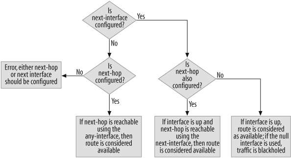
Action groups determine the network path for traffic by defining the next action. Each action group can have multiple entries with a configurable entry ID that determines the order in which they would be applied. An action entry contains the next interface or next hop, which determines the packet’s network path. The next action is monitored for availability; it is considered available only when the next interface is up or the next hop is reachable via an active outgoing route, if only one of them is configured in an entry. If both the next interface and the next hop are configured, the next hop should be reachable using the next interface configured in the action entry. Figure 19-1 shows the algorithm used for determining the network path.
19.1. Traffic Load Balancing
Problem
You have links to two Internet Service Providers (ISPs), and you want to balance the traffic between those two ISP links.
Solution
Configure PBR to load-balance the traffic between the two ISP links. Create an extended access list for the IP addresses, create a match group, and assign the extended access list to the group. Then, create action groups to identify the next-hop router for each ISP:
	set access-list extended 15 src-ip 192.168.100.0/25 entry 1
	set access-list extended 16 src-ip 192.168.100.128/25 entry 1
	set match-group name ISP2
	set match-group ISP2 ext-acl 15 match-entry 10
	set match-group name ISP1
	set match-group ISP1 ext-acl 16 match-entry 10
	set action-group name ISP2
	set action-group ISP2 next-hop 1.1.1.2 action-entry 1
	set action-group name ISP1
	set action-group ISP1 next-hop 3.3.3.2 action-entry 1
Next, create the PBR policy using the match group and action group. Enable PBR on the ingress interface, and apply the PBR policy to the zone:
	set pbr policy name load-balance
	set pbr policy load-balance match-group ISP1 action-group ISP1 1
	set pbr policy load-balance match-group ISP2 action-group ISP2 2
	exit
	set interface ethernet0/0 pbr
	set zone Trust pbr load-balance
You will also need to create the firewall policy to allow this traffic to pass across the device:
	set policy id 1 from "Trust" to "Untrust"  "Any" "Any" "ANY" nat
	    src permit
	set policy id 1
	exit
Discussion
One of the common uses of routing policies is to load-balance traffic between two different ISP connections. Although there are multiple ways to load-balance, the PBR on ScreenOS provides flexibility regarding which hosts or type of traffic you want to send, using different links. For example, you could use an Equal Cost Multipath (ECMP) method to load-balance traffic. However, ECMP will load-balance on a persession basis, which means you have no control over which host behind the firewall will use which link—it will be random. With PBR you’ll get granular control based on the packet’s header, such as the source IP, source port, destination IP, destination port, protocol, and ToS bits. This type of granular control could allow you to send low-priority traffic, such as file-sharing applications or instant messages, using low-speed links, and send corporate traffic using high-speed links.
In this recipe’s solution, the two ISP links are connected to the firewall and have a single IP subnet behind the firewall; therefore, you want to load-balance the traffic based on the source address only. Figure 19-2 shows the topology.
In Figure 19-2, extended access list 15 for source IP subnet 192.168.100.0/25 and extended access list 16 for source IP subnet 192.168.100.128/25were configured. Now, define match groups by identifying which attributes need to be matched (in this example, a match group named ISP1 was created, and you want it to match the IP subnet in extended access list 15). Another match group, ISP2, was created and matched with the IP subnet in extended access list 16. You can define multiple match attributes for the match group—the order of the match attributes is determined by the match-entry option, and it goes in ascending order. In this example, the match entry was defined with a value of 10.
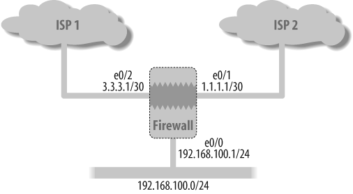
After the match groups are created, create the action groups. Action groups determine what action needs to be performed after the IP packet is matched based on the match group. Action groups named ISP1 and ISP2 were created with an action to route the packets to the next-hop gateway for the respective ISP gateways—that is, 1.1.1.2 and 3.3.3.2. You could also have multiple actions—as with the match groups, the order of the action here is determined by the action-entry option, and it goes in ascending order. In this example, the action entry was defined with a value of 1.
The PBR policy is defined to bring together the match groups and the action groups. Here, the PBR policy named load-balance was created. It defines the IP address to be matched based on match group ISP1, to take action based on action group ISP1, followed by the order sequence. A second policy matches the IP address based on match group ISP2 and action group ISP2. The PBR option is enabled on the incoming interface, ethernet0/0, and the policy was bound to the Trust zone to which the ethernet0/0 interface belongs.
Tip
A common user error in PBR is to misconfigure the PBR policy, or just to forget to bind it, and enable PBR on the interface. For the PBR policy to kick in, the interface and policy binding are important. PBR policy lookup happens only when the first packet is received on the firewall. As such, it is important to know the traffic direction and the incoming interface.
Remember, you still need the firewall policy to allow traffic. Create the firewall policy ID 1 from the Trust zone to the Untrust zone, with any source, any destination, and any service to allow traffic and the Network Address Translation (NAT) source address based on the outgoing interface. See Chapter 7 for more on firewall policy configurations.
19.2. Verify That PBR Is Working for Traffic Load Balancing
Problem
You configured PBR for two ISPs, and you want to verify that the traffic is being load-balanced.
Discussion
To verify that the traffic is being directed as per your PBR configuration, you can review the routing and session state. Use the get route command to see the connected routes; here, the connected routes are ethernet0/1 for the ISP2 link and ethernet0/2 for the ISP1 link, and route IDs 5 and 3, respectively:
SSG->get routeIPv4 Dest-Routes for <untrust-vr> (0 entries) -------------------------------------------------------------------- H: Host C: Connected S: Static A: Auto-Exported I: Imported R: RIP P: Permanent D: Auto-Discovered iB: IBGP eB: EBGP O: OSPF E1: OSPF external type 1 E2: OSPF external type 2 IPv4 Dest-Routes for <trust-vr> (8 entries) -------------------------------------------------------------------- ID IP-Prefix Interface Gateway P Pref Mtr Vsys --------------------------------------------------------------------* 3 3.3.3.0/30 eth0/2 0.0.0.0 C 0 0 Root* 6 1.1.1.1/32 eth0/1 0.0.0.0 H 0 0 Root * 9 2.2.2.0/30 eth0/1 1.1.1.2 S 20 1 Root * 4 3.3.3.1/32 eth0/2 0.0.0.0 H 0 0 Root* 5 1.1.1.0/30 eth0/1 0.0.0.0 C 0 0 Root* 10 4.4.4.0/30 eth0/2 3.3.3.2 S 20 1 Root * 8 192.168.100.1/32 eth0/0 0.0.0.0 H 0 0 Root * 7 192.168.100.0/24 eth0/0 0.0.0.0 C 0 0 Root
Using the get session src-ip command reveals the session from source IP 192.168.100.100, which belongs to match group ISP2 for destination IP 192.168.200.1 using route ID 5, which is the ISP2 link. This shows that the PBR policy was applied and the out-going route was chosen as ISP2. This command also shows that source IP 192.168.100.100 was translated to 1.1.1.1 based on the firewall’s NAT configuration.
SSG->get sess src-ip 192.168.100.100alloc 1/max 48064, alloc failed 0, mcast alloc 0, di alloc failed 0 total reserved 0, free sessions in shared pool 48063 Total 1 sessions according filtering criteria. id 48039/s**,vsys 0,flag 00000010/0000/0001,policy 1,time 1, dip 2 module 0 if 0(nspflag 800801):192.168.100.100/34164->192.168.200.1/768,1,000c29946d55,sess token 4,vlan 0,tun 0,vsd 0,route 7 if 5(nspflag 800800):1.1.1.1/5058<-192.168.200.1/768,1,000585caf0a0, sess token 6,vlan 0,tun 0,vsd 0,route 5Total 1 sessions shown
This example shows that the session from source IP 192.168.100.200, which belongs to match group ISP1 for the same destination IP 192.168.200.1, is using route ID 3, which is the ISP1 link. Also, the source address was translated to 3.3.3.1 based on the firewall policy.
SSG->get sess src-ip 192.168.100.200alloc 1/max 48064, alloc failed 0, mcast alloc 0, di alloc failed 0 total reserved 0, free sessions in shared pool 48063 Total 1 sessions according filtering criteria. id 48019/s**,vsys 0,flag 00000010/0000/0001,policy 1,time 1, dip 2 module 0 if 0(nspflag 800801):192.168.100.200/51060->192.168.200.1/768,1,000c23476a43,sess token 4,vlan 0,tun 0,vsd 0,route 7 if 6(nspflag 800800):3.3.3.1/5127<-192.168.200.1/768,1,0010db3fc210,sess token 6,vlan 0,tun 0,vsd 0,route 3Total 1 sessions shown
See Also
19.3. Prioritize Traffic Between IPSec Tunnels
Problem
You need to prioritize traffic between two IP Security (IPSec) virtual private network (VPN) tunnels based on IP addresses and application to provide redundancy.
Solution
Create two IPSec VPN tunnels for the destination network, and bind to a tunnel interface using Next Hop Tunnel Binding (NHTB) to create two traffic paths:
	set interface "tunnel.1" zone "Trust"
	set interface tunnel.1 ip unnumbered interface ethernet0/0
	set ike gateway "Fast_link_gw1" address 2.2.2.1 Main outgoing-
	    interface "ethernet0/1" preshare xxxxx sec-level standard
	set ike gateway "slow_link_gw2" address 4.4.4.1 Main outgoing-
	    interface "ethernet0/2" preshare xxxxx sec-level standard

	set vpn "Fast_link_gw1" gateway "Fast_link_gw1" no-replay tunnel
	idletime 0 sec-level standard
	set vpn "Fast_link_gw1" monitor rekey
	set vpn "Fast_link_gw1" id 1 bind interface tunnel.1
	set interface tunnel.1 nhtb 2.2.2.1 vpn "Fast_link_gw1"

	set vpn "slow_link_gw2" gateway "slow_link_gw2" no-replay tunnel
	idletime 0 sec-level standard
	set vpn "slow_link_gw2" monitor rekey
	set vpn "slow_link_gw2" id 2 bind interface tunnel.1
	set interface tunnel.1 nhtb 4.4.4.1 vpn "slow_link_gw2"
Use PBR to configure extended access lists based on the high-priority traffic. Then, use the action group to send the high-priority traffic to one of the IPSec VPN tunnels.
Create the second extended access list for all traffic as a catchall from previous access lists. This will also act as a backup tunnel should the primary tunnel fail. Finally, configure the action group to send the low-priority traffic to the second IPSec VPN tunnel.
Tip
If both tunnels are down, the access list will use the default route to forward traffic unencrypted.
	set vrouter "trust-vr"
	set route 2.2.2.0/30 interface ethernet0/1 gateway 1.1.1.2
	set route 4.4.4.0/30 interface ethernet0/2 gateway 3.3.3.2
	set route 192.168.200.0/24 interface tunnel.1 gateway 2.2.2.1
	set route 192.168.200.0/24 interface tunnel.1 gateway 4.4.4.1
	set route 0.0.0.0/0 interface ethernet0/1 gateway 1.1.1.2
	set access-list extended 1 src-ip 192.168.100.0/24 dst-ip
	192.168.200.0/24 dst-port 25-25 protocol tcp entry 1
	set access-list extended 1 src-ip 192.168.100.0/24 dst-ip
	192.168.200.0/24 dst-port 1521-1521 protocol tcp entry 2
	set access-list extended 1 src-ip 192.168.100.0/24 dst-ip
	192.168.200.0/24 dst-port 443-443 protocol tcp entry 3
	set access-list extended 1 src-ip 192.168.100.0/24 dst-ip
	192.168.200.0/24 dst-port 80-80 protocol tcp entry 4
	set access-list extended 1 src-ip 192.168.100.0/24 dst-ip
	192.168.200.0/24 dst-port 9090-9090 protocol tcp entry 5
	set access-list extended 2 src-ip 192.168.100.0/24 dst-ip
	192.168.200.0/24 entry 1
	set match-group name High_Priority_Traffic
	set match-group High_Priority_Traffic ext-acl 1 match-entry 1
	set match-group name Low_Priority_traffic
	set match-group Low_Priority_traffic ext-acl 2 match-entry 1
	set action-group name Send_using_Slow_Link
	set action-group Send_using_Slow_Link next-interface tunnel.1
	next-hop 4.4.4.1 action-entry 1
	set action-group name Send_using_Fast_Link
	set action-group Send_using_Fast_Link next-interface tunnel.1
	next-hop 2.2.2.1 action-entry 1
	set pbr policy name Distribute_Traffic
	set pbr policy Distribute_Traffic match-group High_Priority_Traffic
	action-group Send_using_Fast_Link 1
	set pbr policy Distribute_Traffic match-group Low_Priority_traffic
	action-group Send_using_Slow_Link 2
	exit
	set interface ethernet0/0 pbr Distribute_Traffic
Discussion
We see two redundant IPSec VPN paths for the same destination network, forwarding the high-priority traffic using the fast link, and sending the low-priority traffic using the slow link. The second path acts as a backup to the primary tunnel traffic (failover of low-priority traffic to the fast link was not provided in this example). If both tunnels fail, the traffic is forwarded unencrypted; if you don’t want unencrypted traffic, you can configure null routes for the destination network and blackhole the traffic. Figure 19-3 shows the basic topology.

Configure the tunnel.1 interface in the Trust zone and use an unnumbered IP address for this interface. Then, create an Internet Key Exchange (IKE) gateway named fast_link_gw1 for remote gateway 2.2.2.1, and use the ethernet0/1 interface as the outgoing interface. Create another IKE gateway named slow_link_gw2 for the remote gateway IP address of 4.4.4.1, and use ethernet0/2 as the outgoing interface. Create the VPN for the fast_link_gw1 and bind it to the tunnel.1 interface, and then enable the Monitor and Rekey options for the tunnel. The Monitor and Rekey options will help to ensure that the routes for the remote network are withdrawn from the forwarding table when the tunnel goes down.
Two static routes were created in the device for 192.168.200.0/24 with next-hop gateways of 2.2.2.1 and 4.4.4.1. You have to configure the NHTB entry on the tunnel.1 interface to create two traffic paths, as shown in the following code. The NHTB configuration shows that the routes for the next hop of 2.2.2.1 should use the fast_link_gw1 IPSec VPN, and the routes for the next hop of 4.4.4.1 should use the slow_link_gw2 IPSec VPN. This is required because you are binding both IPSec VPNs to the same tunnel interface.
	set route 192.168.200.0/24 interface tunnel.1 gateway 2.2.2.1
	set route 192.168.200.0/24 interface tunnel.1 gateway 4.4.4.1
	set interface tunnel.1 nhtb 2.2.2.1 vpn "Fast_link_gw1"
	set interface tunnel.1 nhtb 4.4.4.1 vpn "slow_link_gw2"
Now that the IPSec tunnels are set up, all traffic destined for the 192.168.200.0/24 network would be forwarded using the first available route on the lookup. But using this configuration would not provide any traffic engineering, and the goal of this recipe is to distribute traffic between these two IPSec tunnels based on priority, while also providing redundancy for the high-priority traffic. To achieve this, use PBR to identify the high-priority traffic.
The high-priority traffic here is the traffic from source address 192.168.100.0/24 destined to 192.168.200.0/24 for SMTP (25), SQL (1521), HTTPS (443), HTTP (80), and Custom Application Port (9090). All other traffic is low-priority and should use the slow_link_gw2. Create an extended access list ID of 1 for the high-priority traffic, as shown in the following code snippet; the first two lines show extended access list ID 1 created in trust-vr for source IP 192.168.100.0/24, destination IP 192.168.20.0/24, and destination port 25-25 (this is the port range), with the protocol as TCP, and entry 1 showing the sequence order for this access list. Here are the five entries for the different protocols for high-priority traffic:
	Set vr trust-vr
	set access-list extended 1 src-ip 192.168.100.0/24 dst-ip
	192.168.200.0/24 dst-port 25-25 protocol tcp entry 1
	set access-list extended 1 src-ip 192.168.100.0/24 dst-ip
	192.168.200.0/24 dst-port 1521-1521 protocol tcp entry 2
	set access-list extended 1 src-ip 192.168.100.0/24 dst-ip
	192.168.200.0/24 dst-port 443-443 protocol tcp entry 3
	set access-list extended 1 src-ip 192.168.100.0/24 dst-ip
	192.168.200.0/24 dst-port 80-80 protocol tcp entry 4
	set access-list extended 1 src-ip 192.168.100.0/24 dst-ip
	192.168.200.0/24 dst-port 9090-9090 protocol tcp entry 5
Then, configure extended access list ID 2 for all traffic from source IP 192.168.100.0/24 destined to 192.168.200.0/24. There is no mention of the destination ports in this access list, implying that all traffic from source addresses in the range 192.168.100.0/24 to destinations in the range 192.168.200.0/24 will be matched. This way, the configuration will act as a catchall for traffic for access list ID 1, and will match all the protocols in access list ID 1 providing the redundant path.
	Set vr trust-vr
	set access-list extended 2 src-ip 192.168.100.0/24 dst-ip
	192.168.200.0/24 entry 1
Now, define the match group named High_Priority_Traffic and match the extended access list ID 1; then, create the second match group named low_priority_traffic, and match the extended access list ID 2. Define the action group send_using_slow_link with an action set to the next interface of tunnel.1 and the next hop of 4.4.4.1. This action will cause all packets to follow the NHTB entry on tunnel.1 with a next hop of 4.4.4.1, thereby using the slow_Link_gw2 IPSec tunnels. Next, define the action group send_using_fast_link with the action set to the next interface of tunnel.1 and the next hop of 2.2.2.1; this group will cause the packets to follow the NHTB entry on tunnel.1 with the next hop 2.2.2.1, thereby using the fast_link_gw1 IPSec tunnel. Now, define the PBR policy named Distribute_traffic, and as the first entry, define traffic to the High_Priority_traffic match group and action group to use send_using_fast_link, using the sequence order of 1. Then, define traffic to the low_ Priority_traffic match group and action group to use send_using_slow_link, followed by the sequence order of 2.
It is important to note the sequence order for the PBR policy, which is the order for PBR lookup that will be used for matching the traffic. If you configure slow_ priority_traffic out of sequence, the high-priority traffic will never get priority. Therefore, apply the policy to the ethernet0/0 interface, as this is the entry point for the traffic.
	set match-group name High_Priority_Traffic
	set match-group High_Priority_Traffic ext-acl 1 match-entry 1
	set match-group name Low_Priority_traffic
	set match-group Low_Priority_traffic ext-acl 2 match-entry 1
	set action-group name Send_using_Slow_Link
	set action-group Send_using_Slow_Link next-interface tunnel.1
	next-hop 4.4.4.1 action-entry 1
	set action-group name Send_using_Fast_Link
	set action-group Send_using_Fast_Link next-interface tunnel.1
	next-hop 2.2.2.1 action-entry 1
	set pbr policy name Distribute_Traffic
	set pbr policy Distribute_Traffic match-group High_Priority_Traffic
	action-group Send_using_Fast_Link 1
	set pbr policy Distribute_Traffic match-group Low_Priority_traffic
	action-group Send_using_Slow_Link 2
	exit
	set interface ethernet0/0 pbr Distribute_Traffic
Lastly, you need to configure static routes for the tunnel endpoints for the VPN tunnels to establish a default route for all the unencrypted traffic. In this example, the default route will cause all the traffic to go unencrypted when the tunnels are down:
	set route 2.2.2.0/30 interface ethernet0/1 gateway 1.1.1.2
	set route 4.4.4.0/30 interface ethernet0/2 gateway 3.3.3.2
	set route 0.0.0.0/0 interface ethernet0/1 gateway 1.1.1.2
To verify whether the traffic is being forwarded to the expected routes, you can use these commands: get sa, get route, get session, and get int. Based on the preceding configuration, the get sa command shows that the two tunnels are active (A/U means the tunnel is active and up), the tunnel gateway address 2.2.2.1 is the fast_Link_gw1, and the gateway address 4.4.4.1 is the slow_link_gw2, as configured. Please note the Hex ID field for each tunnel; this is used in the session table to forward traffic.
	SSG-> get sa
	total configured sa: 2
	HEX ID    Gateway Port Algorithm    SPI  Life:sec kb    Sta PID vsys
	00000001<  2.2.2.1 500 esp:3des/sha1 e4c116b2  1424 unlim A/U -1  0
	00000001>  2.2.2.1 500 esp:3des/sha1 9bd93a19  1424 unlim A/U -1  0
	00000002<  4.4.4.1 500 esp:3des/sha1 e4c116b3  1514 unlim A/U -1  0
	00000002>  4.4.4.1 500 esp:3des/sha1 9bd93a1a  1514 unlim A/U -1  0
The get route command shows that the routes for destination network 192.168.200.0/24 are active for the two tunnels:
SSG->get routeIPv4 Dest-Routes for <untrust-vr> (0 entries) -------------------------------------------------------------------- H: Host C: Connected S: Static A: Auto-Exported I: Imported R: RIP P: Permanent D: Auto-Discovered iB: IBGP eB: EBGP O: OSPF E1: OSPF external type 1 E2: OSPF external type 2 IPv4 Dest-Routes for <trust-vr> (11 entries) ------------------------------------------------------------------ ID IP-Prefix Interface Gateway P Pref Mtr Vsys ------------------------------------------------------------------ * 3 3.3.3.0/30 eth0/2 0.0.0.0 C 0 0 Root * 6 1.1.1.1/32 eth0/1 0.0.0.0 H 0 0 Root * 19 0.0.0.0/0 eth0/1 1.1.1.2 S 20 1 Root * 9 2.2.2.0/30 eth0/1 1.1.1.2 S 20 1 Root * 4 3.3.3.1/32 eth0/2 0.0.0.0 H 0 0 Root * 5 1.1.1.0/30 eth0/1 0.0.0.0 C 0 0 Root * 10 4.4.4.0/30 eth0/2 3.3.3.2 S 20 1 Root * 8 192.168.100.1/32 eth0/0 0.0.0.0 H 0 0 Root* 17 192.168.200.0/24 tun.1 2.2.2.1 S 20 1 Root * 18 192.168.200.0/24 tun.1 4.4.4.1 S 20 1 Root* 7 192.168.100.0/24 eth0/0 0.0.0.0 C 0 0 Root SSG->
The get int tunnel.1 command shows that the NHTB entries are active (via the U in the “Status” column for the NHTB table), and each next hop is showing the VPN binding tunnel information:
c3-22->get int tun.1Interface tunnel.1: description tunnel.1 number 20, if_info 16168, if_index 1, mode nat link ready vsys Root, zone Trust, vr trust-vr admin mtu 1500, operating mtu 1500, default mtu 1500 *ip 0.0.0.0/0 unnumbered, source interface ethernet0/0 *manage ip 0.0.0.0 bound vpn: Fast_link_gw1 slow_link_gw2Next-Hop Tunnel Binding table Flag Status Next-Hop(IP) tunnel-id VPNS U 2.2.2.1 0x00000001 Fast_link_gw1S U 4.4.4.1 0x00000002 slow_link_gw2
This recipe initiated high-priority traffic for destination IP address 192.168.200.100 using destination port 80, and it is expected to be forwarded to the fast_link_gw1. To see the session entry, use the get session dst-ip 192.168.200.100 dst-port 80 command. The session shows tun 40000001: with an sa-id of 1, and a 4 added to the hex-id of the get sa command. This confirms that the session is forwarded using the Fast_Link based on the PBR configuration.
c3-22->get session dst-ip 192.168.200.100 dst-port 80alloc 6/max 48064, alloc failed 0, mcast alloc 0, di alloc failed 0 total reserved 0, free sessions in shared pool 48058 Total 1 sessions according filtering criteria. id 48047/s**,vsys 0,flag 08000040/0000/0001,policy 320002,time 26, dip 0 module 0 if 0(nspflag 801001):192.168.100.200/4582->192.168.200.100/80,6, 000c29946d55,sess token 4,vlan 0,tun 0,vsd 0,route 7 if 20(nspflag 1000):192.168.100.200/4582<-192.168.200.100/80,6, 000000000000,sess token 5,vlan 0,tun 40000001,vsd 0,route 0 Total 1 sessions shown
Now, initiate the low-priority traffic for the same destination IP address of 192.168.200.100 and destination port of 9999. It shows tun 400000002 and it is the slow_link:
c3-22->get session dst-ip 192.168.200.100 dst-port 9999alloc 8/max 48064, alloc failed 0, mcast alloc 0, di alloc failed 0 total reserved 0, free sessions in shared pool 48056 Total 1 sessions according filtering criteria. id 48036/s**,vsys 0,flag 08000040/0000/0001,policy 320002,time 159, dip 0 module 0 if 0(nspflag 801001):192.168.100.200/4583->192.168.200.100/9999,6,000c29946d55,sess token 4,vlan 0,tun 0,vsd 0, route 7 if 20(nspflag 1000):192.168.100.200/4583<-192.168.200.100/9999,6, 000000000000,sess token 5,vlan 0,tun 40000002,vsd 0,route 0 Total 1 sessions shown
19.4. Redirect Traffic to Mitigate Threats
Problem
You want to redirect user traffic to the Intrusion Detection System (IDS) in the DMZ zone, protecting devices in the Trust zone from downloading malware. Also, you have multiple VR configurations to protect the routing table from external attacks.
Solution
You need to redirect traffic for threat mitigation using multiple VRs.
First, configure zones in the different VRs, assign interfaces to the zones, and assign IP addresses to the interfaces:
	set zone "Trust" vrouter "trust-vr"
	set zone "Untrust" vrouter "untrust-vr"
	set zone "DMZ" vrouter "untrust-vr"
	set interface "ethernet0/0" zone "Trust"
	set interface "ethernet0/1" zone "DMZ"
	set interface "ethernet0/2" zone "Untrust"
	set interface ethernet0/0 ip 172.16.1.1/24
	set interface ethernet0/1 ip 2.2.2.1/30
	set interface ethernet0/2 ip 4.4.4.1/30
Next, configure the firewall policy to allow traffic from the Trust zone to the DMZ zone, and from the DMZ zone to the Untrust zone for IDP inspection (note that you would need to configure the IDP device as needed, and IDP device configuration is beyond the scope of this recipe; therefore, consult the IDP documentation that came with your device):
	set address "Trust" "Trust_network" 172.16.1.0 255.255.255.0
	set address "DMZ" "Filtered_trust_network" 172.16.1.0 255.255.255.0
	set policy id 1 from "Trust" to "DMZ" "Trust_network" "Any"
	    "ANY" permit
	set policy id 1
	set policy id 2 from "DMZ" to "Untrust" "Filtered_trust_network"
	    "Any" "ANY" permit
	set policy id 2
Lastly, configure the PBR to redirect traffic from the Trust network to the IDP device in the DMZ zone:
	set vrouter "untrust-vr"
	set route 0.0.0.0/0 interface ethernet0/2 gateway 4.4.4.2
	exit
	set vrouter "trust-vr"
	set route 2.2.2.2/32 interface ethernet0/1 gateway 2.2.2.2
	set route 0.0.0.0/0 vrouter "untrust-vr" preference 20
	set access-list extended 1 src-ip 172.16.1.0/24 entry 1
	set match-group name threat_check
	set match-group threat_check ext-acl 1 match-entry 1
	set action-group name redirect_for_idp
	set action-group redirect_for_idp next-hop 2.2.2.2 action-entry 1
	set pbr policy name threat_mitigation
	set pbr policy threat_mitigation match-group threat_check action-group redirect_for_
	idp 1
	exit
	set interface ethernet0/0 pbr threat_mitigation
Discussion
This recipe demonstrates traffic redirection to the dedicated threat detection device (IDP/AV) using PBR and blocking malicious traffic into the network. This design requires planning; you need to spend time analyzing network traffic flow and determining which traffic should be redirected to the IDP device. Also, you need to consider how to configure and deploy the IDP device.
There are two VRs: trust-vr and untrust-vr. They are configured with the Trust zone to belong to the trust-vr and have assigned the ethernet0/0 interface to the Trust zone. The Untrust and DMZ zones belong to the untrust-vr, and ethernet0/1 and ethernet0/2 have been assigned to the DMZ and Untrust zones, respectively. The ethernet0/0 interface has the IP address 172.16.1.1/24, the ethernet0/1 interface has the IP address 2.2.2.1/30, and the ethernet0/2 interface has the IP address 4.4.4.1/30. Configuring two VRs provides security to the routing table and prevents internal network addresses from being visible to the outside world.
Firewall policy has been applied to allow traffic from the 172.16.1.0/24 network to any destination (note that the policy will only allow traffic from the Trust zone to the DMZ zone). The DMZ zone has the IDP device, which will inspect the traffic and redirect it back to the firewall. If there is any malicious traffic, it will take necessary action based on the configuration of the IDP device. A second policy from the DMZ zone to the Untrust zone was also added. The address book entry for the DMZ and Trust zones shows the same network, 172.16.1.0/24, but the names are different, showing that the IDP device is filtering traffic.
Configure the default route in the untrust-vr to forward traffic to the Internet using the ethernet0/2 interface and a next-hop gateway of 4.4.4.2:
	set vrouter "untrust-vr"
	set route 0.0.0.0/0 interface ethernet0/2 gateway 4.4.4.2
	exit
The default route in the trust-vr has been configured with a next hop of untrust-vr— this route is required to forward all traffic from the Trust zone to the Internet via the untrust-vr. A host route has been set for the IDP device in the trust-vr. This is an important step, because if you miss this configuration, the traffic will not be redirected to the IDP device. To configure:
	set vrouter "trust-vr"
	set route 0.0.0.0/0 vrouter "untrust-vr" preference 20
	set route 2.2.2.2/32 interface ethernet0/1 gateway 2.2.2.2
Let’s examine the PBR configuration, which redirects traffic based on the routing policy. Create an extended access list ID of 1 with a source address of 172.16.1.0/24 so that all traffic from the 172.16.1.0/24 network is redirected to the IDP device. Then, create the match group named threat_check to be matched with extended list ID 1. Define the action group named redirect_for_idp and set the next-hop gateway as 2.2.2.2.
Create the PBR policy threat_mitigation using the match group threat_check and action group redirect_for_idp. Assign the PBR policy on the ethernet0/0 interface that will receive the incoming traffic. The configuration for this is as follows:
	set vr trust-vs
	set access-list extended 1 src-ip 172.16.1.0/24 entry 1
	set match-group name threat_check
	set match-group threat_check ext-acl 1 match-entry 1
	set action-group name redirect_for_idp
	set action-group redirect_for_idp next-hop 2.2.2.2 action-entry 1
	set pbr policy name threat_mitigation
	set pbr policy threat_mitigation match-group threat_check action-group redirect_for_
	idp 1
	exit
	set interface ethernet0/0 pbr threat_mitigation
19.5. Classify Traffic Using the ToS Bits
Problem
You have latency-sensitive traffic in your network, and you want to classify traffic using the ToS bits in the IP header to determine the next hop. You have two links: one link provides the Quality of Service (QoS) and the other is a best-effort service.
Solution
You need to identify the ToS bits for the latency-sensitive traffic on your network before you start the configuration. Configure the default route for the second link to match the noncritical traffic. Then, create the extended access list for a ToS value, create a match group to match the extended access list, define an action group, and provide the high-reliability link next-hop gateway address:
	set vrouter "trust-vr"
	set route 0.0.0.0/0 interface ethernet0/1 gateway 2.2.2.2
	set access-list extended 10 tos 63 entry 1
	set match-group name High_Priority
	set match-group High_Priority ext-acl 10 match-entry 1
	set action-group name High_Reliability
	set action-group High_Reliability next-hop 4.4.4.2 action-entry 1
	exit
Configure the PBR policy using the match group and action group, and then bind the policy to the incoming interface:
	Set vr trust-vr
	set pbr policy name Critical_traffic
	set pbr policy Critical_traffic match-group High_Priority action-group High_
	Reliability 1
	exit
	set interface ethernet0/0 pbr Critical_traffic
Discussion
The IPv4 header has a 1-byte ToS field (originally defined in RFC 791), and it uses only six bits (0–5), with two bits (6–7) reserved for the future and set at 0. The first two fields of the ToS byte were defined as precedence and type of service subfields:
	   0     1     2     3    4      5     6     7
	+-----+-----+-----+-----+-----+-----+-----+-----+
	|   PRECEDENCE    |      TOS        |  0  |  0  |
	+-----+-----+-----+-----+-----+-----+-----+-----+
The field was redefined in RFC 2474/RFC 2475 and named the DS field, sometimes also referred to as the Differentiated Services Code Point (DSCP). Only six bits are used in the fields, with an additional two bits reserved:
	   0     1     2     3     4     5     6     7
	+-----+-----+-----+-----+-----+-----+-----+-----+
	|               DSCP                |    CU     |
	+-----+-----+-----+-----+-----+-----+-----+-----+
You have to analyze your network traffic and applications before you can use ToS values to determine the traffic path. To best use high-cost links for critical traffic, the applications should be marking the ToS bits in the packet, or you should use network devices to do the marking. It is also important to understand that all the devices in the network path should know how to read the ToS bits for end-to-end QoS.
In this recipe, the extended access list 10 for the ToS value of 63 was configured. This is the specified decimal value equal to 0x3F in Hex. The value of 63 indicates the highest-priority traffic on the network. You can configure the ToS value range of 0–255 for the extended access list. The ToS value of 0 is the default for “normal” traffic on the network. The match group High_Prioritymatches with extended access list 10 as the first entry. A High_Reliability action group is defined with a next hop of 4.4.4.2 as the gateway for the link providing QoS.
	set vrouter "trust-vr"
	set access-list extended 10 tos 63 entry 1
	set match-group name High_Priority
	set match-group High_Priority ext-acl 10 match-entry 1
	set action-group name High_Reliability
	set action-group High_Reliability next-hop 4.4.4.2 action-entry 1
	exit
The PBR policy Critical_trafficwas created with match group High_Priority to match the traffic with a ToS value of 63. Using the action group High_Reliability, the traffic is forwarded to the next-hop gateway address of the link providing QoS. This policy was bound to the ethernet0/0 interface to trigger the PBR for the incoming traffic.
	Set vr trust-vr
	set pbr policy name Critical_traffic
	set pbr policy Critical_traffic match-group High_Priority action-group High_
	Reliability 1
	exit
	set interface ethernet0/0 pbr Critical_traffic
The second link provides best-effort service. For all other traffic, the default route to interface ethernet0/1 was configured using the next-hop gateway address of 2.2.2.2.
set vr trust-vr route 0.0.0.0/0 interface ethernet0/1 gateway 2.2.2.2
This feature assumes that all subsequent packets will have the same ToS values as the first packet when the session was created. Once the session has been created, the ToS byte is not inspected for PBR decisions; the PBR policy is applied per flow and not per packet.
19.6. Block Unwanted Traffic with a Blackhole
Problem
You’re receiving unwanted traffic of various types, attempting to probe your network. You can’t prevent this traffic from reaching your router, but you want to make sure it never reaches your network. You want to send it to a “dead end” or null route; this is commonly referred to as routing the traffic to a blackhole.
Solution
Configure an extended access list to match the traffic pattern you want to blackhole:
	set access-list extended 20 src-ip 172.16.1.0/24 dst-ip 172.19.50.0/24
	tos 63 entry 10
Now, configure a match group and assign the extended access list created for the traffic pattern:
	set match-group name black_hole_traffic
	set match-group black_hole_traffic ext-acl 20 match-entry 1
Configure an action group and set the next interface as null; this will blackhole the traffic:
	set action-group name black_hole_nh
	set action-group black_hole_nh next-interface null action-entry 1
Next, create a PBR policy using the match group and action group for the implementation:
	set pbr policy name prevent_mis_use
	set pbr policy prevent_mis_use match-group black_hole_traffic
	action-group black_hole_nh 1
Finally, bind the PBR policy to the desired interface, zone, or VR. In this case, bind it to the interface:
	set interface ethernet0/0 pbr prevent_mis_use
	c3-21->
Discussion
There are multiple ways to blackhole traffic. For example, you could use a null route or configure a policy to deny traffic. However, these methods are only able to blackhole based on the destination IP address or the five tuples: source IP, source port, destination IP, destination port, and protocol. PBR provides all of these methods, as well as ToS bits, which is useful for ensuring that no application is misusing the network resources and is still able to pass traffic within the permitted parameters. It is also a good tool for dynamic threat mitigation—you can just put in the access list and reduce CPU utilization on the firewall. One disadvantage of using the PBR for blackholing traffic is logging. The PBR will not be able to log the dropped packets in the traffic log, which can be achieved by the firewall deny policy. Careful consideration is required before choosing one of the methods available for dropping traffic.
The intention here was to ensure that proper network resources are being used, and to prevent users from network 172.16.1.0/24 from sending traffic to 172.19.50.0/24 with a ToS value of 63—any traffic matching this access list will be dropped. To achieve this, first configure an extended access list ID of 20 with an IP address of 172.16.1.0/24, a destination IP of 172.19.50.0/24, and a ToS value of 63. This access list will match for any destination port; you do not have to choose a destination port because protocols between these networks are not supposed to have a ToS value of 63.
Now, configure the match group black_hole_traffic and match the extended access list ID 20 you just created. Define action group black_hole_nh to blackhole the next hop by specifying the next interface as null. When the PBR policy is matched, it will find the next interface as null and will inform the flow processing engine to drop this packet.
To blackhole traffic, define the PBR policy prevent_mis_use and use the match group black_hole_traffic and action group black_hole_nh. Bind the policy to interface ethernet0/0—this is the entry point for the traffic. You can bind the policy to the interface, zone, or VR.
19.7. View Your PBR Configuration
Solution
Use the get vr <vr_name> pbr config command to view the complete configuration for the PBR:
	SSG-> get vr trust-vr pbr config
	set access-list extended 1 src-ip 192.168.100.0/24 dst-ip
	192.168.200.0/24 dst-port 25-25 protocol tcp entry 1
	set match-group name High_Priority_Traffic
	set match-group High_Priority_Traffic ext-acl 1 match-entry 1
	set action-group name Send_using_Fast_Link
	set action-group Send_using_Fast_Link next-interface tunnel.1
	next-hop 2.2.2.1 action-entry 1
	set pbr policy name Distribute_Traffic
	set pbr policy Distribute_Traffic match-group High_Priority_Traffic
	action-group Send_using_Fast_Link 1
	set interface ethernet0/0 pbr Distribute_Traffic
Discussion
The configuration is sometimes very large on the firewall, and it becomes difficult to discover which configuration lines relate to a particular feature. The PBR configuration on the trust-vr is shown here, and all the components for the PBR policy are shown together, making it easier to troubleshoot configuration issues. In essence, you need five components for PBR to work:
- Extended access list
This is the basic traffic-matching access list.
- Match groups
You can combine multiple access lists into groups as required for added flexibility.
- Action group
You essentially define what next steps you want to achieve, such as the outgoing interface and/or outgoing next-hop gateway address.
- PBR policy
Think of this as a firewall policy. You define the match criteria using the match groups, and the next steps for the matched traffic using the action group.
- Bound PBR policy
After you have created the PBR policy, you have to bind it to the incoming traffic interface, zone, or VR to achieve your goal.
You can also view each component separately using the selective component in the command line, as shown here:
	SSG-> get vr trust-vr pbr ?
	access-list          pbr access-list
	action-group         pbr action-group
	configuration        show pbr configuration
	match-group          pbr match-group
	policy               pbr policy name