
Chapter 3. Wireless
3.0. Introduction
Wireless local area networks (WLANs) provide obvious benefits over wired networks, in that they link network devices without wires. WLAN uses spread-spectrum or Orthogonal Frequency-Division Multiplexing (OFDM) modulation technology (based on radio waves to enable communication between devices in a limited area, also known as the basic service set).
IEEE 802.11 is the standard defined for the WLAN. It uses Carrier Sense Multiple Access with Collision Avoidance (CSMA/CA) as the access method. Multiple standards are defined under the 802.11 umbrella standards; 802.11a was the first standard defined for WLAN, and it uses OFDM at a 5 GHz frequency, providing 54 Mbps throughput (in theory). The most commonly used standards, however, are the 802.11b and 802.11g, and they operate in Direct Sequence Spread Spectrum(DSSS) and OFDM in a 2.4 GHz frequency, providing 11 Mbps and 54 Mbps. 802.11g is backward-compatible with 802.11b; however, 802.11b is not backward-compatible with 802.11a. Therefore, you would see a lot of wireless Access Point (AP) devices that support 802.11b/g on the same radio and 802.11a on a separate radio. The NS-5GT supports only the 802.11b/g standard; the SSG5 and SSG20 support the 802.11a/b/g standards using dual-band radio.
The 802.11 Standards
The 802.11b/g is prone to interferences from common household devices, such as microwaves and cordless phones. The channels available for 802.11b/g are 1–13, with the most commonly used channels being 1, 6, and 11, as these are nonoverlapping (all other channels interfere with each other). Extended channels (12 and 13) are not available to North America and some other countries.
You can use the exec wlan find-channel command to find the best channel, and you can either hard-set the channel or leave it at auto. To hard-set the channel, use the set wlan 0 channel command if you have a two-radio device such as the SSG5, or the set wlan channel command for single-radio devices such as the NS-5GT. Here is example output of the find-channel command:
	ssg5-> exec wlan find-channel
	Traffic will be disrupted during the scan
	Channel 1 is the best 2.4G radio channel to use
	Channel 64 is the best 5G radio channel to use
Figure 3-1 shows the various components in an 802.11 WLAN, as listed here:
- Station (STA)
A terminal with an access mechanism to the wireless medium and radio contact to the AP.
- Basic service set (BSS)
A group of stations using the same radio frequency that communicate with one another. Each BSS is identified by a Service Set Identifier (SSID).
- Access point (AP)
A station integrated into the WLAN and the distribution system.
- Extended service set (ESS)
A set of infrastructure BSSs.
- Distribution system (DS)
An interconnection network from one logical network (ESS) based on several BSSs.

APs periodically advertise themselves by broadcasting a Beacon Frame, which includes the following information:
SSID (blanked out when SSID suppression is on)
Supported rates (the Beacon Frame lists all supported rates; e.g., for 11G, supported rates are 1, 2, 5.5, 11, 6, 9, 11, 18, 24, 36, 48, and 54 Mbps)
Supported security (authentication and encryption capabilities; e.g., the Temporal Key Integrity Protocol [TKIP] and the Advanced Encryption Standard [AES])
Other information, such as channels, country, and vendor-specific features
You can perform a wireless site survey by using the exec wlan site-survey command, which will disrupt the traffic during the scan. In the following example output, the SSG5 device shows the SSID (SSID on index 3 is suppressed) and the AP Media Access Control (MAC) addresses:
	SSG5-> exec wlan site-survey
	Traffic will be disrupted during the scan
	index   channel    rssi     mac             ssid
	======================================================
	1        7(g)         64    0010dba8bc71     casper2
	2        7(g)         54    0010dba8bc70     casper3
	3       11(g)         14    0010dba8bc72
	4       11(g)         36    0014f6e547a0     Secured
	========================================================
The stations can also identify the AP using a Probe Request and Response. The station sends Probe Requests on each channel to advertise its capability (e.g., supported rate) and to announce the SSID it is seeking (this is especially needed if the SSID has been suppressed at the AP). The AP answers the Probe Request using the Probe Response, which basically contacts the same information as in the Beacon Frame. The AP should respond immediately because the station won’t listen for long; stations wait for responses for only around 20 ms on the current channel, and then repeat the process on the next channel.
The Wireless Station State transition occurs in the following sequence, as shown in Figure 3-2:
The station and AP discover each other using Passive Scanning (via the Beacon Frame broadcast from the AP) or Active Scanning (using the Probe Request and Probe Response). While in this state, the station cannot transmit data.
The station identity is verified using authentication methods based on the capabilities of the station and the AP. In this state, the station still cannot transmit data.
When the station and AP are associated, the station and AP can exchange data.
Wireless networks face all the threats that wired networks face, including eavesdropping, authorization, masquerading, loss or modification, repudiation, and sabotage. To supply security to the wireless network, security services were provided under the various 802.11 standards.
The legacy security services of IEEE 802.11 are achieved by the Entity Authentication Service and the Wired Equivalent Privacy (WEP) mechanism. WEP uses the Rivest Cipher 4 (RC4) stream cipher to provide confidentiality, data origin authentication/data integrity, and access control in conjunction with layer management. IEEE 802.11 authentication comes in two flavors: Open-System Authentication and Shared-Key Authentication. Open-System Authentication is a null authentication algorithm engaged during the State 2 transition shown in Figure 3-2. The station sends the authentication message set to Open, and the AP simply responds with a success message. Shared-Key Authentication supports authentication of stations as either a member of those who know a shared secret key or a member of those who do not. The required secret shared key is presumed to have been delivered to participating stations via a secure channel that is independent of IEEE 802.11. Using the Shared-Key Authentication method in State 2 of Figure 3-2, the station sends the authentication message set to Shared Key (the shared key itself is not sent), the AP sends challenge text to the station, and then the station generates the challenge response data from the challenge text and, using the WEP algorithm, sends it back as a response. If the message integrity check is verified, the AP will respond with a success message. Figure 3-3 shows this entire sequence.


WEP is well known for its weakness: tools are available on the Internet for getting access to the shared secret key. To overcome WEP’s serious security weakness, IEEE amended the 802.11 security services in the 802.11i specifications. While the IEEE was amending the specifications, the Wi-Fi Alliance came out with Wi-Fi Protected Access (WPA) based on the draft standard of IEEE 802.11i.
It was revised in WPA2, based on the final specifications of 802.11i. IEEE 802.11i defined the Robust Security Network (RSN) as the standard protocol for the WLAN. The 802.11i specifications rely on IEEE 802.1x for authentication and key management services and use an encryption protocol, such as the Counter Mode with Cipher Block Chaining Message Authentication Code Protocol (CCMP), Wireless Robust Authentication Protocol (WRAP), or TKIP, for data protection.
The RSN relies on the IEEE 802.1x entity above IEEE 802.11 to provide authentication and key management services. With this model, decisions regarding which packets are permitted onto the DS are made by IEEE 802.1x in addition to IEEE 802.11 MAC.
IEEE 802.1x is a standard developed for port-based network access control. It provides authentication to devices connected to a LAN port by establishing a point-to-point connection, or it blocks access to the port if authentication fails. It is based on the Extensible Authentication Protocol (EAP), defined in RFC 2284 and revised in RFC 3748. To understand 802.1x you need to first understand a few concepts about the Point-to-Point Protocol (PPP), EAP, and 802.1x itself.
The Point-to-Point Protocol
The Point-to-Point Protocol (PPP) was typically used for dial-up user access. One of the functions of PPP was authentication, and users would dial in to the Remote-Access Server (RAS) and provide their username/password to authenticate. Most organizations wanted to provide security for authentication, so a new protocol, EAP, evolved. EAP is designed to provide a general framework for different authentication methods, such as challenge/response, smart cards, and public key infrastructure (PKI).
With EAP as the standard protocol, interoperability and compatibility of authentication methods become easier across different network devices. Typically, a user would dial in to a RAS and provide authentication details using EAP—the RAS would be independent of the authentication methods employed within EAP and it would act like a deliveryman and pass EAP packets between the end-user and the authentication server.
The EAP packet can be encapsulated in PPP or IEEE 802 without requiring IP. EAP encapsulated in LAN (usually Ethernet) environments is described in IEEE 802.1x. EAP in wireless is described in IEEE 802.11i. 802.11i relies on 802.1x for its authentication and key management services. 802.1x has three components:
- Supplicant
The user or client that wants to authenticate
- Authentication server
The server that performs the authentication (typically a Remote Access Dial-In User Service [RADIUS] server)
- Authenticator
The device that has to provide access to the user (typically a wireless AP)
More than 40 authentication methods are defined for EAP. Some of the most commonly used authentication methods are EAP-TLS, EAP-TTLS, EAP-PEAP, and EAP-MD5. EAP-TLS (Transport Layer Security) uses certificates for user and server authentication, and for dynamic session-key generation support by most RADIUS servers. EAP-TTLS (Tunneled Transport Layer Security) requires only a server-side certificate and a valid username and password for authentication (Steel-Belted Radius supports TTLS). EAP-PEAP (Protected EAP) requires only server-side certificates and a valid username and password, and it provides key exchange, session resumption, fragmentation, and reassembly (the Microsoft Internet Authentication Service (IAS) server and Steel-Belted Radius support this). EAP-MD5 (Message Digest 5) uses a challenge and response process to verify MD5 hashes.
While deploying 802.11 with 802.1x, the entire authentication and key distribution procedure happens in the following sequence (as shown in Figures Figure 3-4, Figure 3-5, and Figure 3-6).

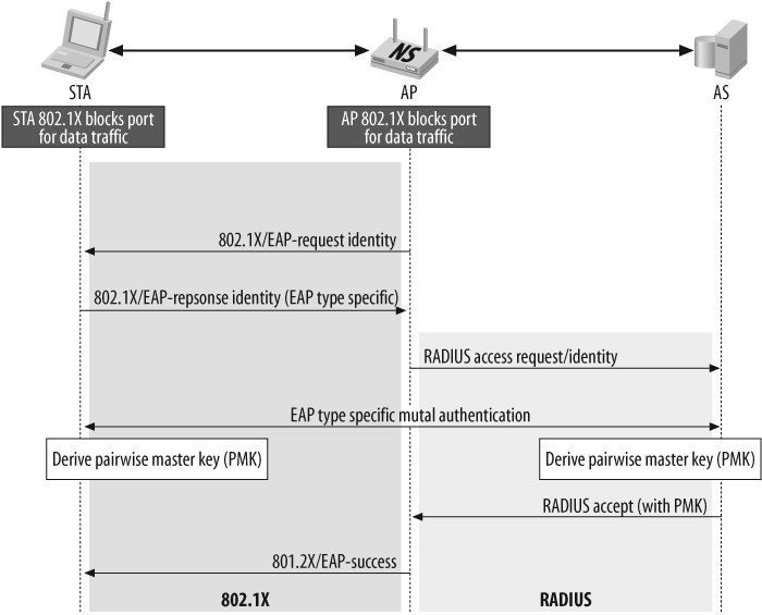
Discovery:
Determine promising parties with whom to communicate
AP advertises network security capabilities to STAs (Stations) using the Beacon Frames
802.1x authentication:
Centralize network admission policy decisions at the authentication server
STA determines whether it does indeed want to communicate
Mutually authenticate STA and authentication server
Generate Master Key as a side effect of authentication
Generate Pairwise Master Key (PMK) as an access authorization token
Authentication server moves (does not copy) PMK to STA’s AP
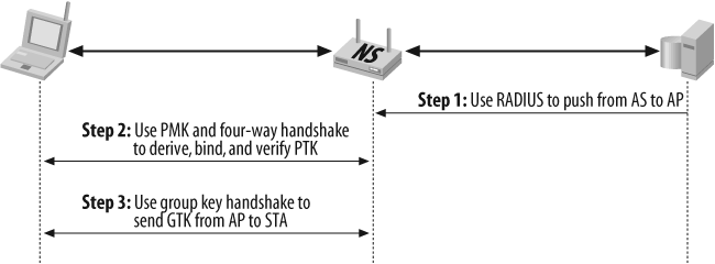
802.1x key management:
Bind PMK to STA and AP
Confirm that both AP and STA possess PMK
Generate fresh PTK (Pairwise Transient Key)
Prove each peer is live
Synchronize PTK use
Distribute GTK
3.1. Use MAC Filtering
Solution
Configure MAC filtering on the WLAN network and set up a strict access control list (ACL) on the WLAN configuration:
	set wlan acl mode strict
	set wlan acl 000f02020202 allow
	set wlan acl 000c01010101 allow
Discussion
When you enable MAC filtering on the WLAN, the firewall will allow association of only those MAC addresses which are listed in the ACL. Although this is not a very secure way to restrict wireless access, it is one method among other security measures that you can use to deter unwanted users.
There are three modes for MAC filtering:
- Disabled
The default mode; no MAC filtering will be done by the firewall
- Enabled
Allows any MAC address to associate with the AP and deny the configured Deny MAC address
- Strict
Allows only the configured Allow MAC addresses to associate with the AP, and denies everything else
You can view the MAC filtering configuration using the get wlan acl command. The following example shows that the WLAN ACL mode is strict, and it has one Deny MAC address, and two Allow MAC addresses:
	ssg5-> get wlan acl
	wlan acl mode strict

	denied mac address
	1. 000000000001

	allow mac address
	1. 000f00000000
	2. 000c01010101
You can view the event log using the get log event command to verify the MAC filtering. Here, a user with MAC address 00:0f:b5:22:bf:a2 was attempting to associate to the corp SSID and was denied by the ACL:
	2001-10-06 10:20:06 system notif 00564 Wireless station event: Station
	                                 000fb522bfa2 is denied by ACL, SSID:
	                                 corp.
You can also view the current association to the wireless network using the get interface command. In the following example, a user with a MAC address of <wireless_interface_name> association00:0f:02:02:02:02 is associated on the wireless0/0interface, and encryption is enabled on this connection. Also note that it is operating in mode 11g:
	SSG5-> get interface wireless0/0 association
	index   mac address     state   encryption     mode
	======================================================
	1       000f02020202    assoc   on             11g
	======================================================
3.2. Configure the WEP Shared Key
Solution
Configure the SSID with an authentication type of shared-key, define the WEP key, and bind the SSID to the wireless interface:
	set ssid name pizza
	set ssid pizza key-id 1 length 40 method asciitext a1b2c default
	set ssid pizza authentication shared-key
	set ssid pizza interface wireless0/0
	exec wlan reactivate
To configure the infrastructure to enable traffic flow through the AP, you must create a zone, attach a wireless interface to the zone, configure the IP address, enable a Dynamic Host Configuration Protocol (DHCP) server service on the wireless interface, configure security policy, and activate the wireless connection:
	set zone name "wzone1"

	set interface "wireless0/0" zone "wzone1"
	set interface wireless0/0 ip 172.16.254.1/24

	set interface wireless0/0 dhcp server service
	set interface wireless0/0 dhcp server auto
	set interface wireless0/0 dhcp server option gateway 172.16.254.1
	set interface wireless0/0 dhcp server option netmask 255.255.255.0
	set interface wireless0/0 dhcp server ip 172.16.254.10 to 172.16.254.15

	set policy from "wzone1" to "Untrust" "Any" "Any" "ANY" nat src permit
	exec wlan reactivate
You must also configure the client for WEP-shared authentication to associate with this AP.
Discussion
You should configure the minimum of WEP authentication and encryption on your wireless network to deter casual snooping. Although it is very easy to crack WEP encryption, it will deter users from looking for easy access to your wireless network.
In this example, we chose WEP shared-key as the authentication and encryption method to protect the wireless network. For WEP, you can configure three different authentication types:
- Open authentication
Requires no authentication key, and anybody specifying the SSID can associate with the AP. You can configure open authentication with or without encryption. The encryption algorithm used for WEP is RC4 for encryption and decryption.
- Shared-key authentication
Requires the client PC to provide a preshared authentication key to associate with the AP.
- Auto authentication
Follow these instructions to use shared-key authentication.
First, create an SSID called Pizza; define the key-id 1 in ASCII text as the default key. You can define multiple keys for this SSID to utilize different keys with different users. (Always remember that the key-id on the firewall should match the key-id on the client PC; for example, if you specify key-id 4 on the firewall, you should create key-id 4 on the PC as well.)
Now, configure the Pizza SSID to use shared-key authentication and bind the SSID to the wireless0 interface.
You’ll now need to configure the infrastructure to enable traffic flow and separate the users on the wireless network by putting them in a separate zone.
Create a new zone called Wzone1 (on the NS-5GT, this zone is preconfigured) and assign the wireless0/0 interface to this zone. Define an IP address, 172.16.254.1/24, to the wireless0/0 interface. Enable users to get their IP addresses automatically, enable DHCP server service on the wireless0/0 interface, and configure the gateway address and IP address range. You also need to configure the security policy to allow traffic to traverse the Wzone1 to the Untrust zone. For this discussion, you are providing open access in the policy, you may have to create a more restricted policy based on your organization’s security policy.
Finally, you need to activate the wireless configuration on the AP. Execute the exec wlan reactivate command to enable the wireless AP. Remember to always run this command whenever you perform any wireless configuration changes, or else the AP will not work as planned. This command will restart the wireless AP.
Based on the client PC software, you will need to configure the wireless network settings (consult your client software manuals for the configurations). Use the get event command to view the client connectivity status.
The following output shows three different events: the first event shows that the stations were associated with SSID Pizza after being authenticated with shared-key authentication; the second event shows that the authentication failed due to an incorrect shared key; and the third event shows that the authentication type is incorrect because the user tried to connect using the open authentication type.
	2007-08-23 10:04:50 system notif 00564 Wireless station event: station
	                                 0019d2c8d24e is associated, SSID:
	                                 pizza.

	2007-08-23 10:04:13 system notif 00564 Wireless station event: Station
	                                 0019d2c8d250 Shared-Key authentication
	                                 failed: Challenge failure, SSID:
	                                 pizza.

	2007-08-23 10:03:56 system notif 00564 Wireless station event: Station
	                                 0019d2c8d24e Authentication type not
	                                 accepted, Type: OPEN, SSID: pizza.
3.3. Configure the WPA Preshared Key
Problem
You want to secure a wireless network using WPA with a preshared key. You don’t have the infrastructure for 802.1x authentication, and would like to use WPA with a preshared key.
Solution
Define the SSID with the authentication type as WPA-Auto-PSK, and the encryption algorithm as auto, and then bind the SSID to the wireless interface:
	set ssid name Sunnyvale
	set ssid Sunnyvale client-isolation
	set ssid Sunnyvale authentication wpa-auto-psk passphrase JnPr!234
	   encryption auto
	set ssid Sunnyvale interface wireless1
Configure the infrastructure to enable traffic flow through the AP, create the zone, attach the wireless interface to the zone, configure the IP address, enable DHCP server service on the wireless interface, configure the security policy, and activate the wireless connection:
	set zone name "corp-wireless"

	set interface "wireless0/1" zone "corp-wireless"
	set interface wireless0/1 ip 172.17.200.1/24

	set interface wireless0/1 dhcp server service
	set interface wireless0/1 dhcp server auto
	set interface wireless0/1 dhcp server option gateway 172.17.200.1
	set interface wireless0/1 dhcp server option netmask 255.255.255.0
	set interface wireless0/1 dhcp server ip 172.17.200.10 to
	172.17.200.20

	set policy from "corp-wireless" to "trust" "Any" "Any"
	"ANY" permit

	exec wlan reactivate
Configure the client for WPA or WPA2 preshared key authentication to associate with this AP.
Discussion
WPA is a more secure authentication and encryption method than WEP. It is a good measure to ensure that only trusted users can associate with the wireless AP. ScreenOS firewalls support WPA authentication using 802.1x and the static key (a.k.a. the preshared key).
This recipe uses the WPA-PSK (preshared key) method for wireless protection. You can configure WPA-PSK in three ways:
- WPA-PSK authentication
This requires that the users support only WPA with a preshared key. WPA is based on the IEEE 802.11i draft specifications.
- WPA2-PSK authentication
This requires that the users support only WPA2 with a preshared key. WPA2 is based on the IEEE 802.11i final specifications.
- WPA-AUTO-PSK authentication
This will accept WPA or WPA2 with preshared key authentication.
This recipe uses WPA-AUTO-PSK authentication to allow connectivity from a WPA-or WPA2-supported client.
First, an SSID called Sunnyvale was created, and then the authentication type was defined as wpa-auto-psk with the passphrase JnPr!234 and the encryption mode set to auto. We also enabled client isolation to prevent client-to-client bridging.
Next, the SSID was bound to the wireless1 interface. The preshared key was secured only to the extent of its password strength; the passphrase should not be vulnerable to dictionary attacks, and should be composed of random alphanumeric and special characters. Also, the passphrase should be kept secret; otherwise, anybody with the passphrase will be able to decrypt the traffic. Because every user should connect using the passphrase, it is hard to keep it a secret. You should consider using other methods to secure your traffic over the wireless network, such as the IP Security (IPSec)/SSL virtual private network (VPN), or use 802.1x servers.
We then needed to configure the infrastructure to enable traffic flow, and we separated the users on the wireless network by putting them in a separate zone. The new zone, called corp-wireless, was created and assigned a wireless0/1 interface, defined as IP address 172.17.200.1/24. To enable users to get IP addresses automatically, we enabled DHCP server service on the wireless0/1 interface, and configured the gate-way address and IP address range. We configured the security policy to allow traffic to traverse corp-wireless zone to the Untrust zone. (In this example, we are providing open access in the policy; you may have to create a more restricted policy based on your organization’s security policy.)
Finally, to activate the wireless configuration on the AP, we executed the exec wlan reactivate command to enable the wireless AP. Remember to always run this command whenever you perform any wireless configuration changes; otherwise, the AP will not work as planned.
Based on the client PC software, you will need to configure the wireless network settings (consult your client software manuals regarding configurations). Then, use the get event command to view the client connectivity status. Here is an example of a successful association with the WPA client:
	2007-08-23 15:52:11 system notif 00564 Wireless station event: Station
	                                 0019d2c8d250 WPA authentication passed,
	                                 SSID: Sunnyvale.
	2007-08-23 15:52:11 system notif 00564 Wireless station event: Station
	                                 0019d2c8d250 WPA authentication
	                                 negotiating, SSID: Sunnyvale.
	2007-08-23 15:52:11 system notif 00564 Wireless station event: Station
	                                 0019d2c8d250 WPA authentication
	                                 starting, SSID: Sunnyvale.
	2007-08-23 15:52:10 system notif 00564 Wireless station event: station
	                                 0019d2c8d250 is associated, SSID:
	                                 Sunnyvale.
	2007-08-23 15:52:10 system notif 00564 Wireless station event: Station
	                                 0019d2c8d250 Open authentication
	                                 passed, SSID: Sunnyvale
Here is an example of the client association using WPA2 in the event log:
	2007-08-23 15:52:31 system notif 00564 Wireless station event: Station
	                                 0019d2c8d24e WPA2 authentication
	                                 passed, SSID: Sunnyvale.
	2007-08-23 15:52:31 system notif 00564 Wireless station event: Station
	                                 0019d2c8d24e WPA2 authentication
	                                 negotiating, SSID: Sunnyvale.
	2007-08-23 15:52:31 system notif 00564 Wireless station event: Station
	                                 0019d2c8d24e WPA2 authentication
	                                 starting, SSID: Sunnyvale.
	2007-08-23 15:52:30 system notif 00564 Wireless station event: station
	                                 0019d2c8d24e is associated, SSID:
	                                 Sunnyvale.
	2007-08-23 15:52:30 system notif 00564 Wireless station event: Station
	                                 0019d2c8d24e Open authentication
	                                 passed, SSID: Sunnyvale.
And here is an example of the client failing due to an incorrect passphrase while using WPA2 in the event log:
	2007-08-23 15:52:05 system notif 00564 Wireless station event: station
	                                 0019d2c8d24e is disassociated, SSID:
	                                 Sunnyvale.
	2007-08-23 15:52:05 system notif 00564 Wireless station event: Station
	                                 0019d2c8d24e WPA2 authentication
	                                 failed: Station timeout, SSID:
	                                 Sunnyvale.
	2007-08-23 15:52:04 system notif 00564 Wireless station event: Station
	                                 0019d2c8d24e WPA2 authentication MIC
	                                 check failed, SSID: Sunnyvale.
	2007-08-23 15:52:01 system notif 00564 Wireless station event: Station
	                                 0019d2c8d24e WPA2 authentication
	                                 starting, SSID: Sunnyvale.
	2007-08-23 15:52:01 system notif 00564 Wireless station event: station
	                                 0019d2c8d24e is associated, SSID:
	                                 Sunnyvale.
	2007-08-23 15:52:01 system notif 00564 Wireless station event: Station
	                                 0019d2c8d24e Open authentication
	                                 passed, SSID: Sunnyvale
3.4. Configure WPA Using 802.1x with IAS and Microsoft Active Directory
Problem
You want to secure a wireless network with WPA using 802.1x with IAS and Microsoft Active Directory.
Solution
Configure the auth-server using an account-type of 802.1x, and select Radius as the auth-server type:
	set auth-server "MyServer" server-name "172.24.28.199"
	set auth-server "MyServer" account-type 802.1X
	set auth-server "MyServer" radius secret "RADIUS_SECRET"
Configure the SSID with an authentication type of wpa-auto and an encryption type of auto; associate the 802.1x auth-server, and then bind the SSID to the wireless interface:
	set ssid name Secured
	set ssid Secured client-isolation
	set ssid Secured authentication wpa-auto encryption auto auth-server
	   MyServer
	set ssid Secured interface wireless0
Configure the infrastructure to enable traffic flow through the AP by creating a zone, attaching a wireless interface to the zone, configuring the IP address, enabling DHCP server service on the wireless interface, configuring the security policy, and finally, activating the wireless connection:
	set zone name "wzone1"
	set interface "wireless0/0" zone "wzone1"
	set interface wireless0/0 ip 172.16.254.1/24
	set interface wireless0/0 dhcp server service
	set interface wireless0/0 dhcp server auto
	set interface wireless0/0 dhcp server option gateway 172.16.254.1
	set interface wireless0/0 dhcp server option netmask 255.255.255.0
	set interface wireless0/0 dhcp server ip 172.16.254.10 to
	172.16.254.15

	set policy from "wzone1" to "Untrust" "Any" "Any" "ANY" nat src
	permit

	exec wlan reactivate
Use this link to configure Microsoft Windows to provide the 802.1x authentication service: http://www.microsoft.com/technet/network/wifi/ed80211.mspx.
Discussion
Using WPA with the 802.1x authentication method is considered a better wireless network security method when compared to WPA-PSK and WEP. However, it has dependencies on other network services, such as the 802.1x-aware RADIUS server and its backend infrastructure. Based on your network authentication service, the deployment may be different.
In this recipe, we used the Microsoft IAS server as the RADIUS server, which inter-acts with Active Directory in the backend to provide user authentication. We used a standalone Certificate Authority (CA) server to generate a server certificate for the RADIUS server, installed it on the RADIUS server, and installed the CA certificate on the RADIUS server and the end-user host. For this recipe, we used the EAP-PEAP authentication type with a secured password (EAP-MSCHAP v2). Figure 3-7 illustrates the topology used in this recipe.

On the firewall, we configured the authentication server named "MyServer" and specified its IP address, then selected the account-type as 802.1x, and used RADIUS as the account type with RADIUS_SECRET. The RADIUS_SECRET used should match the secret configured on the Microsoft IAS server.
	set auth-server "MyServer" server-name "172.24.28.199"
	set auth-server "MyServer" account-type 802.1X
	set auth-server "MyServer" radius secret "RADIUS_SECRET"
Next, we configured the wireless components. First, we created an SSID named Secured, and configured it with the WPA-AUTO authentication method and an encryption of auto, and associated the RADIUS server with "MyServer". Then, we bound the Secured SSID to the wireless0 interface. We also enabled client isolation to prevent client-to-client bridging. You can specifically configure WPA or WPA2, or you can choose WPA-AUTO to allow WPA and WPA2 clients to associate. As the encryption method, you can specify AES or TKIP.
	set ssid name Secured
	set ssid Secured client-isolation
	set ssid Secured authentication wpa-auto encryption auto auth-server
	   MyServer
	set ssid Secured interface wireless0
We now need to configure the infrastructure to enable traffic flow. Create a new zone called wzone1 and assign the wireless0/0 interface to this zone (this interface also has a binding to the SSID Secured on the wireless side). Assign the IP address 172.16.254.1/24 to the wireless0/0 interface, and enable the DHCP server service on the interface to allow the clients to get the IP address automatically. By default, the Domain Name System (DNS) settings from the Untrust interface are propagated to the clients. If you want to control any of the DHCP options, you can configure them using the DHCP options on the interface (in this example, we configured the gate-way and netmask options).
Next, create a firewall policy to allow traffic to traverse the zones. In this example, we provided open access to the users in wzone1 to Untrust for any source, destination, and service. You may have to create a more restricted policy based on your organization’s security policy. We have also enabled Port-Address Translation (PAT) Network Address Translation (NAT) using the IP address of the Untrust interface. (You can deploy other types of NAT based on your network requirements; see Chapter 8 for the types of NAT supported.)
Finally, you need to activate the wireless configuration on the AP. Use the exec wlan reactivate command to enable the wireless AP. Remember to always run this command whenever you perform any wireless configuration changes; otherwise, the AP will not work as planned.
	set zone name "wzone1"
	set interface "wireless0/0" zone "wzone1"
	set interface wireless0/0 ip 172.16.254.1/24
	set interface wireless0/0 dhcp server service
	set interface wireless0/0 dhcp server auto
	set interface wireless0/0 dhcp server option gateway 172.16.254.1
	set interface wireless0/0 dhcp server option netmask 255.255.255.0
	set interface wireless0/0 dhcp server ip 172.16.254.10 to 172.16.254.15

	set policy from "wzone1" to "Untrust" "Any" "Any" "ANY" nat src permit

	exec wlan reactivate
To troubleshoot wireless connectivity on the firewall, use the get event command to view the status of the clients. The following code snippet shows an example of a successful client connecting using WPA and 802.1x. The client first sends the probe request for 802.1x as the authentication method. Then, it will associate with the open authentication and start the 802.1x authentication process, after which the WPA authentication will be negotiated.
	2007-08-25 17:10:50 system notif 00564 Wireless station event: Station
	                                 0019d2c8d250 WPA authentication passed,
	                                 SSID: Secured.
	2007-08-25 17:10:50 system notif 00564 Wireless station event: Station
	                                 0019d2c8d250 WPA authentication
	                                 negotiating, SSID: Secured.
	2007-08-25 17:10:49 system notif 00564 Wireless station event: Station
	                                 0019d2c8d250 WPA authentication
	                                 starting, SSID: Secured.
	2007-08-25 17:10:49 system info  00527 IP address 172.16.254.10 is
	                                 assigned to 0019d2c8d250.
	2007-08-25 17:10:49 system notif 00614 [1X] host 0019.d2c8.d250 passed
	                                 authentication on interface wireless0/
	                                 0 with 802.1X session id 1.
	2007-08-25 17:10:49 system notif 00564 Wireless station event: Station
	                                 0019d2c8d250 got key from
	                                 RADIUS server, SSID: Secured.
	2007-08-25 17:10:49 system notif 00614 [1X] host 0019.d2c8.d250 started
	                                 authentication on interface wireless0/
	                                 0 with 802.1X session id 1.
	2007-08-25 17:10:49 system notif 00564 Wireless station event: station
	                                 0019d2c8d250 is associated, SSID:
	                                 Secured.
	2007-08-25 17:10:49 system notif 00564 Wireless station event: Station
	                                 0019d2c8d250 Open authentication
	                                 passed, SSID: Secured.
	2007-08-25 17:10:49 system notif 00614 [1X] host 0019.d2c8.d250 started
	                                 authentication on interface wireless0/
	                                 0 with 802.1X session id 1.
Here is an example of the get event command output when the user disconnects from the AP:
	2007-08-25 17:10:28 system notif 00614 [1X] host 0019.d2c8.d250 logged
	                                 off interface wireless0/0 with 802.1X
	                                 session id 1.
	2007-08-25 17:10:28 system notif 00564 Wireless station event: station
	                                 0019d2c8d250 is disassociated, SSID:
	                                 Secured.
And here is an example of the client association using WPA2 in the event log:
	2007-08-25 17:09:44 system info  00527 IP address 172.16.254.11 is
	                                 assigned to 0019d2c8d24e.
	2007-08-25 17:09:44 system info  00527 DHCP server on interface
	                                 wireless0/0 received DHCPDISCOVER from
	                                 0019d2c8d24e requesting out-of-scope
	                                 IP address 172.17.200.11/0.0.0.0.
	2007-08-25 17:09:39 system notif 00564 Wireless station event: Station
	                                 0019d2c8d24e WPA2 authentication
	                                 passed, SSID: Secured.
	2007-08-25 17:09:38 system notif 00564 Wireless station event: Station
	                                 0019d2c8d24e WPA2 authentication
	                                 negotiating, SSID: Secured.
	2007-08-25 17:09:38 system notif 00564 Wireless station event: Station
	                                 0019d2c8d24e WPA2 authentication
	                                 starting, SSID: Secured.
	2007-08-25 17:09:38 system notif 00614 [1X] host 0019.d2c8.d24e passed
	                                 authentication on interface wireless0/
	                                 0 with 802.1X session id 2.
	2007-08-25 17:09:38 system notif 00564 Wireless station event: Station
	                                 0019d2c8d24e got key from RADIUS
	                                 server, SSID: Secured.
	2007-08-25 17:09:26 system notif 00614 [1X] host 0019.d2c8.d24e started
	                                 authentication on interface wireless0/
	                                 0 with 802.1X session id 2.
	2007-08-25 17:09:26 system notif 00564 Wireless station event: station
	                                 0019d2c8d24e is associated, SSID:
	                                 Secured.
	2007-08-25 17:09:26 system notif 00564 Wireless station event: Station
	                                 0019d2c8d24e Open authentication
	                                 passed, SSID: Secured.
	2007-08-25 17:09:25 system notif 00614 [1X] host 0019.d2c8.d24e started
	                                 authentication on interface wireless0/
	                                 0 with 802.1X session id 2.
The following is an example of a failed connection—the user either configured a wrong EAP type (e.g., a used certificate when the auth server was expecting EAP-MSCHAP), or provided a wrong username and password for authentication:
	2007-08-25 17:15:09 system notif 00614 [1X] host 0019.d2c8.d250 failed
	                                 authentication on interface wireless0/
	                                 0 with 802.1X session id 2.
	2007-08-25 17:15:09 system notif 00564 Wireless station event: Station
	                                 0019d2c8d250 did not pass
	                                 authentication, SSID: Secured.
	2007-08-25 17:14:57 system notif 00614 [1X] host 0019.d2c8.d250 started
	                                 authentication on interface wireless0/
	                                 0 with 802.1X session id 2.
	2007-08-25 17:14:57 system notif 00564 Wireless station event: station
	                                 0019d2c8d250 is associated, SSID:
	                                 Secured.
	2007-08-25 17:14:57 system notif 00564 Wireless station event: Station
	                                 0019d2c8d250 Open authentication
	                                 passed, SSID: Secured.
	2007-08-25 17:14:57 system notif 00614 [1X] host 0019.d2c8.d250 started
	                                 authentication on interface wireless0/
	                                 0 with 802.1X session id 2.
get int is another command you can use to check whether the user is able to associate with the AP. The following code is example output of the <interface_name> associationwireless0 interface; the host with the 00:19:d2:c8:d2:50 MAC address is associated with encryption using 11a mode:
	ssg5-> get int w0 ass
	index   mac address       state    encryption     mode
	========================================================
	1       0019d2c8d250      assoc    on             11a
You can also get more detail on the associated client by using the get interface command. The following example shows the client MAC address and the state of the client associated using <interface_name> association <mac_address_of_client>11a mode. It also shows the encryption type used (AES for unicast and TKIP for multicast). The Power Save Mode is on. The RX Data Rate is in Mbps which indicates the last received frame speed, and the Rx Signal Strength is Signal/Noise in dB. You’ll also see the Media Specific Data Unit (MSDU) receive and transmit counters.
	ssg5-> get int w0 ass 0019d2c8d250
	MAC Address: 0019d2c8d250 State: assoc
	WLAN Mode: 11a AID: 49153
	Encryption: on
	Ciphers: aes(unicast), tkip(multicast)
	Power Save Mode on
	RX Data Rate: 0.25, RX Signal Strength: 38
	    MSDU        Data        Mcast       dropped     Errors
	rx  8193        3370        165         0           1
	tx  3208        3243        0           0           1
	ssg5->
The get ssid command will display all the SSID configurations on the firewall, with the authentication type, cipher type, and interface to which it is bound:
	ssg5-> get ssid

	SSID information table:
	             Supp-    Client-  Authen-
	Name       ression  Isolation tication      Cipher  Interface   Radio
	======================================================================
	Sunnyvale disabled  enabled   wpa-auto-psk  auto    wireless0/1 both
	Secured   disabled  disabled  wpa-auto      auto    wireless0/0 both
You can also get detailed information regarding the SSID by using the get ssid <SSID_NAME> command. For example, the following code will display the interface it is bound to, SSID suppression information, client-isolation state, authentication type, cipher type, and rekey interval:
	ssg5-> get ssid Secured
	SSID Secured:
	  bound on wireless0/0
	  suppression disabled
	  client isolation disabled
	  authentication: WPA-AUTO
	  cipher: auto
	  rekey-interval: 1800
For troubleshooting 802.1x issues, you may want to use the commands get dot1x session and get dot1x statistics:
	ssg5-> get dot1x sess
	allocated 2 freed 253 alloc ok 76 fail 0 free ok 74 fail 0
	  (1)(0019d2c8d24e)(00000001)(wireless0/0)(Root) 802.1X RADIUS
	  (2)(0019d2c8d250)(00000001)(wireless0/0)(Root) 802.1X RADIUS
	total 2 session(s)
	ssg5->
The dot1x session table shows the total number of dot1x connections made. The out-put shows the two users who are connected and their MAC addresses. These sessions are established, and are kept open until the users are connected to the AP.
	ssg5-> get dot1x statistics
	--------------------------------------------------------------------
	Interface wireless0/0 802.1X statistics:
	in eapol             139 | out eapol        138 | in start        86
	in logoff             26 | in resp/id        31 | in resp         78
	out req/id            81 | out req          132 | in invalid       0
	in len error           0 |
	Interfacewireless0/0 802.1X diagnostics:
	while connecting:
	enter                  0 | eap logoff         0 |
	while authenticating:
	enter                  0 | auth success       0 | auth timeout    24
	auth fail             24 | auth reauth        0 | auth start      82
	auth logoff           11 |
	while authenticated:
	auth reauth            0 | auth start         0 | auth logoff      4
	backend:
	response             145 | challenge         47 | other request   51
	non-nak resp          78 | auth success       6 | auth fail        0
	-----------
The get dot1x statistics output shows the packet counts for each wireless interface, how many packets were received for in EAPOL, the total number of packets for the logoff request in logoff, the total number of packets received, and the responses sent out to the RADIUS server.
3.5. Configure WPA with the Steel-Belted Radius Server and Odyssey Access Client
Problem
You want to configure the Steel-Belted Radius server and Odyssey Access Client for wireless connection.
Solution
To configure the firewall as the AP, first you must configure the auth server using an account type of 802.1x and select RADIUS as the auth server type:
	set auth-server "MyServer" server-name "172.24.28.199"
	set auth-server "MyServer" account-type 802.1X
	set auth-server "MyServer" radius secret "RADIUS_SECRET"
Then, configure the SSID with an authentication type of wpa-auto and an encryption type of auto, associate the 802.1x auth server, and bind the SSID to the wireless interface:
	set ssid name Sunnyvale
	set ssid Sunnyvale client-isolation
	set ssid Sunnyvale authentication wpa-auto encryption auto auth-server
	   MyServer
	set ssid Sunnyvale interface wireless0
To configure the infrastructure to enable traffic flow through the AP, create the zone, attach a wireless interface to the zone, configure the IP address, enable the DHCP server service on the wireless interface, configure the security policy, and activate the wireless connection:
	set zone name "wzone1"
	set interface "wireless0/0" zone "wzone1"
	set interface wireless0/0 ip 10.1.1.1/24
	set interface wireless0/0 dhcp server service
	set interface wireless0/0 dhcp server auto
	set interface wireless0/0 dhcp server option gateway 10.1.1.1
	set interface wireless0/0 dhcp server option netmask 255.255.255.0
	set interface wireless0/0 dhcp server ip 10.1.1.10 to 10.1.1.20

	set policy from "wzone1" to "Untrust" "Any" "Any" "ANY" nat src permit

	exec wlan reactivate
To install and configure the Steel-Belted Radius server and Odyssey Access Client, follow these steps (these steps are also outlined in the Getting Started and Administration guides, available from the Steel-Belted Radius support site):
Install the Steel-Belted Radius server on a Windows server that is a member of, or belongs to, a domain that has the trust relationship with the domain where the user credentials are stored.
Use the Steel-Belted Radius administrator to configure the RADIUS client (i.e., the wireless AP acting as the authenticator).
Add the Windows domain user, or the group that contains the user you want to authenticate.
Configure the Authentication Policies with the EAP methods and certificates.
Install the Odyssey Access Client on the PC that will act as a supplicant.
Configure the Odyssey Access Client for the authentication parameters.
Discussion
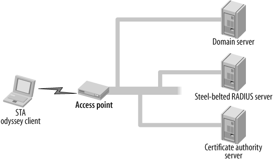
Selecting 802.1x authentication service products can be overwhelming—many freeware and shareware applications are available, and some products are available within the Steel-Belted Radius and Odyssey Access Client that provide 802.1x security in addition to other features, such as uniform security policy enforcement across all network access methods. In this recipe, we use the Steel-Belted Radius server as the RADIUS server, the Odyssey Access Client for the PC as the client, and the Juniper NetScreen Firewall as the AP. Figure 3-8 illustrates the topology.
On the firewall, we configured the authentication server named "MyServer" and specified the IP address of the server which will host the Steel-Belted Radius server, then selected the account type as 802.1x and used RADIUS as the account type with RADIUS_SECRET. The RADIUS_SECRET used should match the secret configured on the Steel-Belted Radius server.
	set auth-server "MyServer" server-name "172.24.28.199"
	set auth-server "MyServer" account-type 802.1X
	set auth-server "MyServer" radius secret "RADIUS_SECRET"
To configure the wireless components, first create an SSID named Sunnyvale and configure the WPA-AUTO authentication method, set the encryption to auto, and associate it to the RADIUS server "MyServer". Then, bind the secured SSID to the wireless0 interface.
We also enabled client isolation to prevent client-to-client bridging. You can specifically configure WPA or WPA2, or you can choose WPA-AUTO to allow both WPA and WPA2 clients to connect. You can also specify the encryption method as AES or TKIP.
	set ssid name Sunnyvale
	set ssid Sunnyvale client-isolation
	set ssid Sunnyvale authentication wpa-auto encryption auto auth-server
	   MyServer
	set ssid Sunnyvale interface wireless0
We now need to configure the infrastructure to enable traffic flow. Create a new zone called wzone1, and assign the wireless0/0 interface to this zone. This interface also has a binding to the SSID Sunnyvale on the wireless side. Assign the IP address 10.1.1.1/24 to the wireless0/0 interface, and enable DHCP server service on the interface to allow clients to get the IP address automatically. By default, the DNS settings from the Untrust interface are propagated to the clients, so if you want to control any of the DHCP options, you can configure them on the interface. In the example, we configured the gateway and netmask options.
You need to create a firewall policy to allow traffic to traverse the zones. In this example, we provided open access to the users in wzone1 to Untrust for any source, destination, and service. You may have to create a more restricted policy based on your organization’s security policy. We enabled PAT NAT using the interface IP address of the Untrust interface. You can deploy other types of NAT based on your network requirements. Refer to Chapter 8 for the types of NAT supported.
Finally, we need to activate the wireless configuration on the AP. Execute the exec wlan reactivate command to enable the wireless AP. Remember to always run this command whenever you perform any wireless configuration changes; otherwise, the AP will not work as planned.
	set zone name "wzone1"
	set interface "wireless0/0" zone "wzone1"
	set interface wireless0/0 ip 10.1.1.1/24
	set interface wireless0/0 dhcp server service
	set interface wireless0/0 dhcp server auto
	set interface wireless0/0 dhcp server option gateway 10.1.1.1
	set interface wireless0/0 dhcp server option netmask 255.255.255.0
	set interface wireless0/0 dhcp server ip 10.1.1.10 to 10.1.1.20

	set policy from "wzone1" to "Untrust" "Any" "Any" "ANY" nat src
	permit

	exec wlan reactivate
Installing the Steel-Belted Radius server
Now we must install the Steel-Belted Radius server on a Windows server that belongs to a domain that has a trust relationship with the domain where the user credentials are stored.
Before you install the Steel-Belted Radius server, ensure that no other RADIUS servers are installed on the host (e.g., IAS). To check on a Windows 2003 server, select Add/Remove Windows Components Networking. Internet Authentication Service should be unchecked, as shown in Figure 3-9.

You can download the Steel-Belted Radius server as a demo version from the following link for full functionality for 30 days, after which you must purchase a permanent license:
| http://www.juniper.net/customers/support/products/aaa_802/sbr_demo.jsp |
Start the installation using the executable you downloaded. Use the wizard to fill in the following sequences:
Provide the User Name and Organization details. Select the “Install 30-day trial” license key.
Based on your network requirements, choose the RADIUS server type. In this example, we chose Global Enterprise Edition.
Choose the install directory for the RADIUS server and any custom settings you need.
Provide the administrator account information, which you will use to administer the Steel-Belted Radius server.
Choose the server type you would like to configure on this system. For this example, we chose the standalone server.
Select to start the Steel-Belted Radius Service after the installation.
If you have an RSA server on your network, and you want to use two-factor authentication, you can choose to register now with the RSA server.
Complete the Steel-Belted Radius server installation. Note the URL regarding how to launch the administrator to manage the RADIUS server.
Launch the web browser to manage the server at the URL that was provided at the completion of the installation. Click on the Launch link (see Figure 3-10) to access the Steel-Belted Radius Administrator.

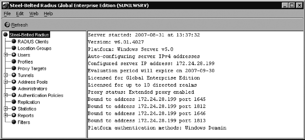
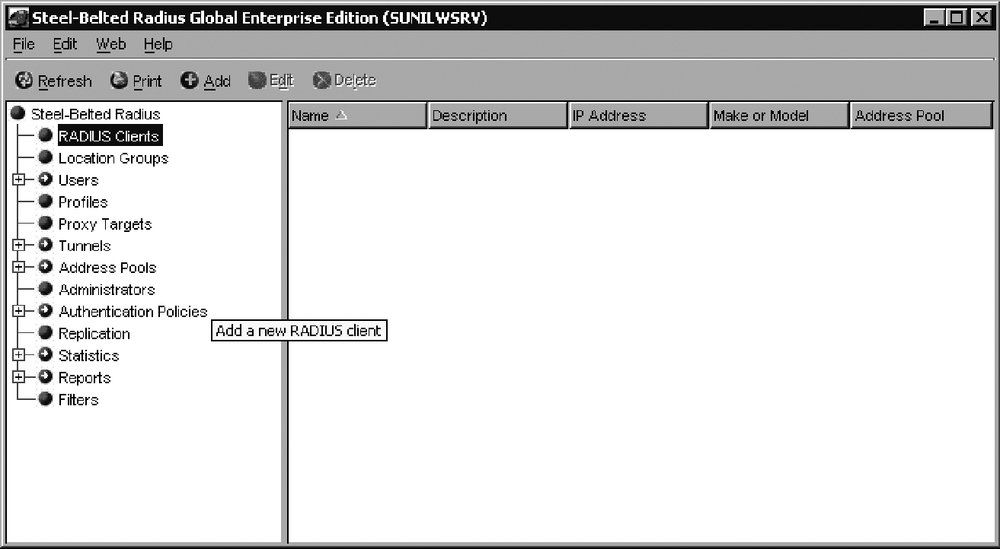
Provide the login username and password to manage the server when prompted (this is the account information you chose during the installation for administration). After the login, you will see the Steel-Belted Radius Server Administrator GUI shown in Figure 3-11.
Select RADIUS Clients, and add a new RADIUS client to the server. As shown in Figure 3-12, the RADIUS client is the wireless AP IP address from which the authentication request will be sent.
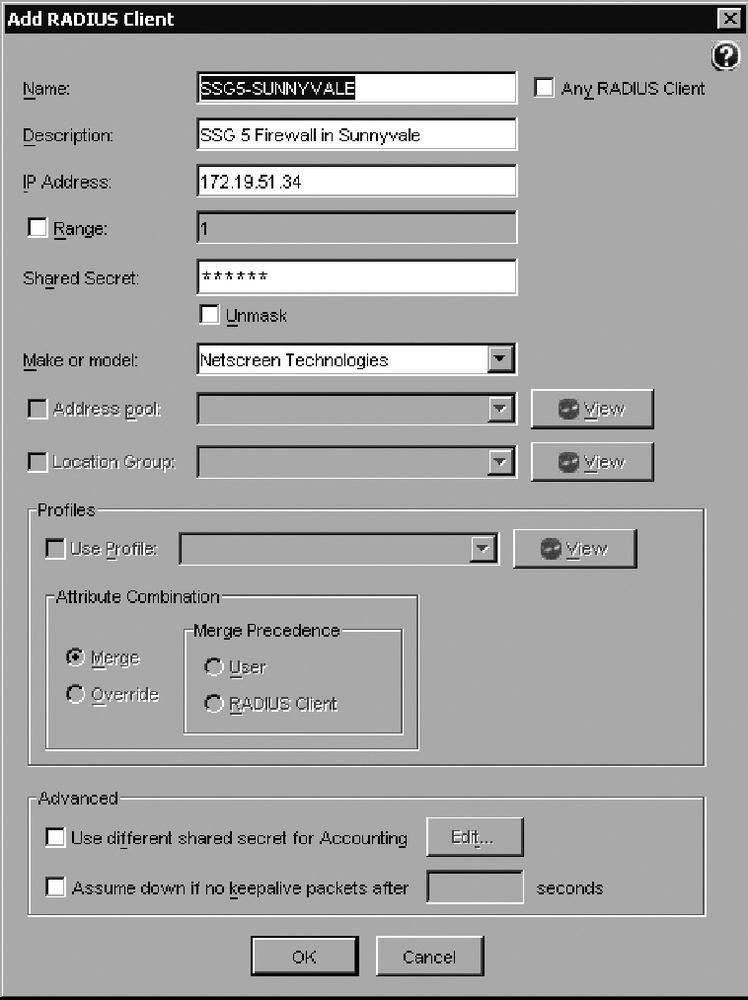
In this recipe, we configured the RADIUS client as SSG5-SUNNYVALE, as shown in Figure 3-13; provided the IP address of the SSG5 firewall, and set the RADIUS secret as configured on the firewall. As shown, select Netscreen Technologies in the “Make or model” box.
Configure the users you want to authenticate, as shown in Figure 3-14, by clicking on Add Domain User, clicking on the Browse button to choose the Domain and User groups, and authenticating Domain Users in the SUNILW domain.

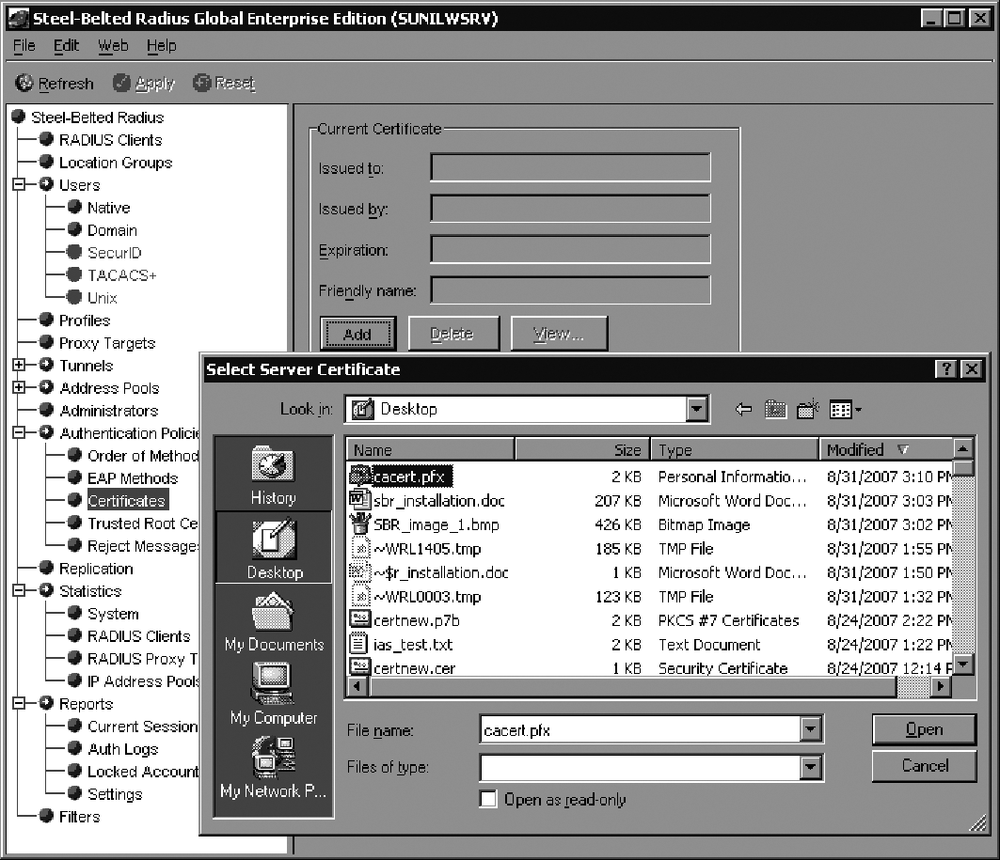
Load the certificate you have generated for the Steel-Belted Radius server. Based on your CA, you need to export the certificate, including the private key, to a file. Then, using the Steel-Belted Radius administrator, select Authentication Policies → Certificates → Add, and provide the certificate filename with a .pfx extension to import the certificate, as shown in Figure 3-15. This is an important step for the client so that it can communicate with the auth server and authenticate. The certificate you load into Steel-Belted Radius must have an intended purpose of Server-Authentication.
Under the Authentication Policies, select the EAP methods you want to deploy on your network, as shown in Figure 3-16.
Configure the order of the authentication methods for EAP negotiation by selecting Authentication Policies → Order of Methods and choosing the auth methods in the Active Authentication methods. It is best to select only the methods you want to use, and to remove the methods you don’t want to deploy; if you have too many methods chosen, you could cause an EAP method mismatch. In this example, we selected EAP-PEAP and Windows Domain Group, as shown in Figure 3-17; selected EAP-PEAP and clicked on “EAP setup” on the toolbar; checked “Use EAP authentication only”; selected the Windows Domain Group and EAP to use MS-CHAP V2; and checked the “Handle via Auto-EAP first” method. After changing the configuration, we clicked the Apply button to confirm the changes.


The RADIUS server configuration is now complete. You need to configure the Odyssey Client and wireless AP to authenticate users. You can monitor the statistics counters for the RADIUS clients, as shown in Figure 3-18.

You can also view the successful auth requests under Reports → Auth-Logs. Choose the successful authentication request logs, select the date, and click on View to review the logs. To view the failed auth requests, select Reports → Auth-Logs, choose the failed authentication request logs, select the date, and click View to review the logs.
Installing the Odyssey Access Client on the PC
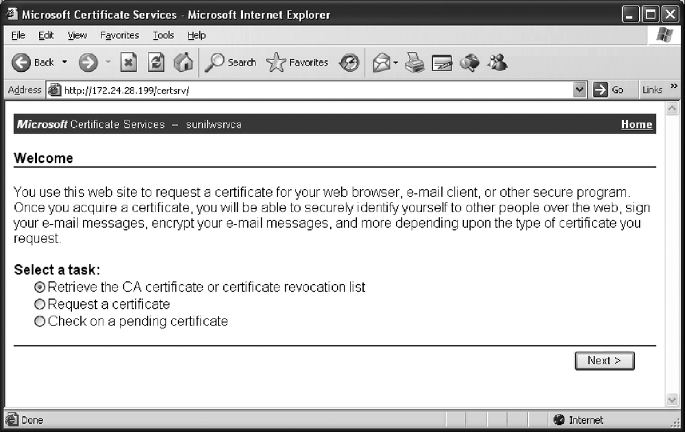
Now you need to install the Odyssey Access Client on the PC that needs to connect to the wireless network and authenticate itself using 802.1x authentication. Before you install the Odyssey Access Client, you need to load the CA certificate that issued the certificate to the RADIUS server—this is required to authenticate the RADIUS server. In our recipe, we used the Microsoft CA server to issue certificates for the RADIUS server, so we need to just install the CA Server certificate. You can browse to your CA server using a URL similar to the one shown in Figure 3-19, click on “Retrieve the CA certificate or certificate revocation list”, and install the CA certificate to the PC.
You can download the Odyssey Access Client demo version from the same URL from which you downloaded the Steel-Belted Radius server evaluation: http://www.juniper.net/customers/support/products/aaa_802/sbr_demo.jsp. You will get a 30-day demo license using the download software. Begin the installation using the down-loaded executable by completing the wizard panels that begin with Figure 3-20.
Provide the username, organization detail, and license key, or select the 30-day evaluation license and complete the wizard installation.
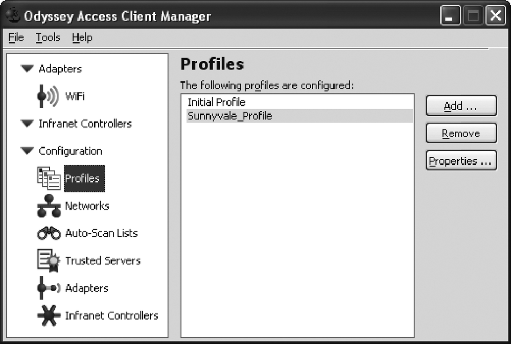
Now, start the Odyssey Access Client Manager to configure the wireless adapter to authenticate with the Steel-Belted Radius server through the firewall AP. After you launch the Odyssey Access Client Manager, open the Configuration bin, and click on Profiles to open a screen similar to Figure 3-21. Add a new profile to set up the authentication method for your network.

In this recipe, we created the Sunnyvale_Profile. With it highlighted, click on the Properties button to give the profile specific information. In a screen similar to that shown in Figure 3-22, in the User Info tab, we provided the login name, selected “Permit login using password”, and chose “Prompt for login name and password”. If the PC is already attached to the domain controller, you can use the Windows password. You may also use certificates to authenticate instead of the username/password.
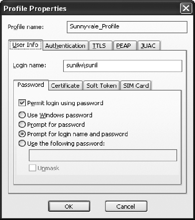
Next, in the Authentication tab, select the authentication protocols you want to use. We chose EAP-PEAP and EAP-TTLS; however, we will use only EAP-PEAP in this example. In the PEAP tab, select the inner EAP protocol information. In this example, we used EAP-MS-CHAP-V2 and moved it to the top of the protocol list. This completes the configuration. Choose OK to save the profile.
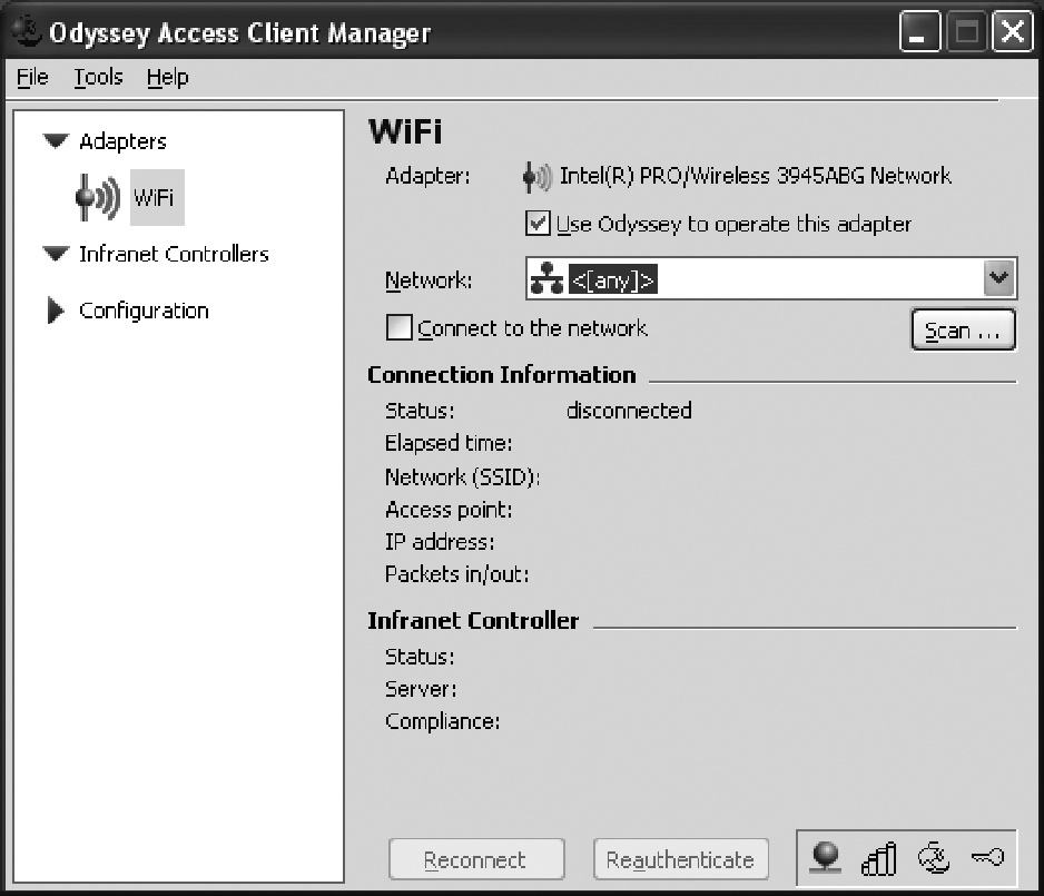
Open the Adapter bin shown in Figure 3-23, and configure the SSID for the AP. Click on the “Use Odyssey to operate this adapter” checkbox shown in Figure 3-23.
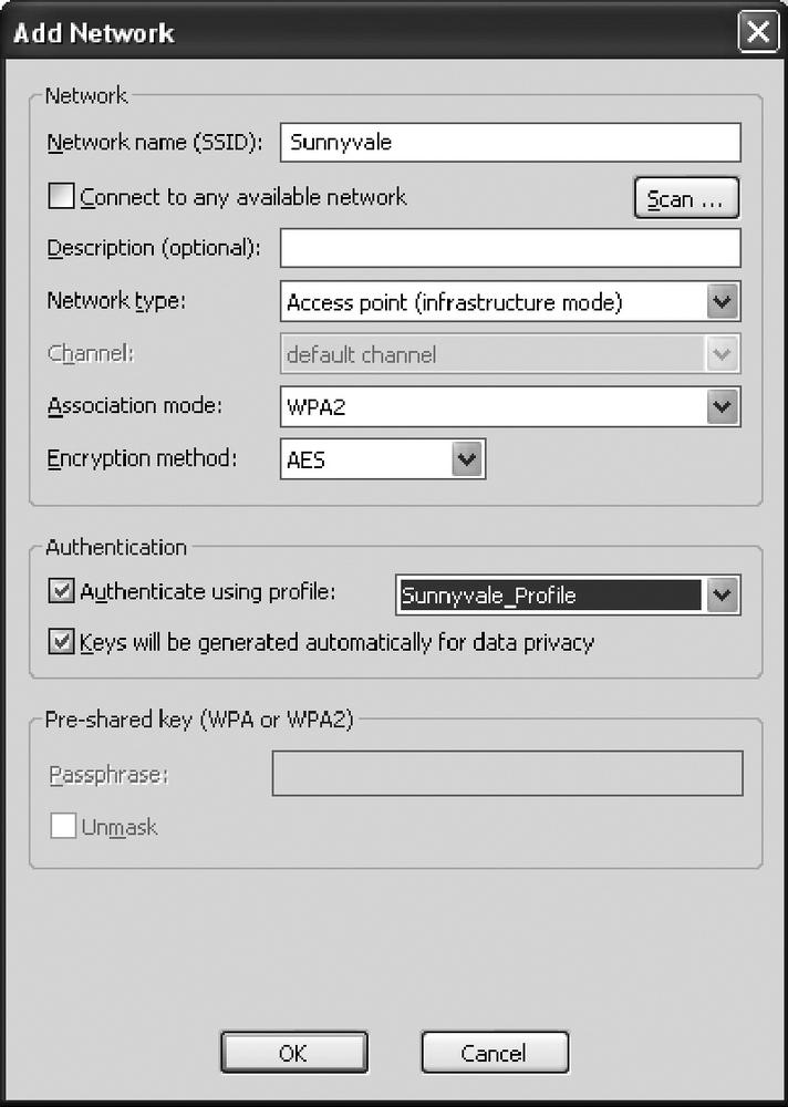
Click on the Scan button to scan for the SSID for the wireless network. Select the SSID to which you want to connect. After you select the SSID, the Add Network window will open, as shown in Figure 3-24, and will allow you to configure the authentication details. We used the WPA2 association mode and AES encryption. Select “Authenticate using profile” and provide the profile we just created—Sunnyvale_Profile —to use the authentication methods for this AP. Click on OK to connect to the AP using 802. 1x authentication.
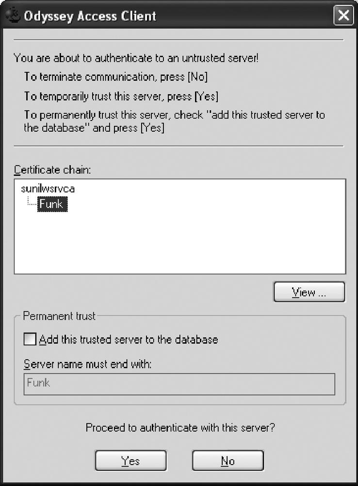
The certificate window will pop up to validate the RADIUS Server Certificate, as shown in Figure 3-25. You can view the certificate and then click Yes to accept. You may also want to add this to the trusted servers to avoid seeing this pop-up window next time.
Because we selected the prompt for the username/password in the profile, we are asked to authenticate by providing the user’s password. After successful authentication, the status will show as “open and authenticated”, as shown in Figure 3-26. It will also show the IP address assigned to the PC, the AP MAC address, and the packets in/out count.

On the firewall, use the get event command output to check the user authentication status. The following output represents a successful authentication log message:
	2007-09-04 11:03:51 system notif 00564 Wireless station event: Station
	                                 001b776779a9 WPA2 authentication
	                                 passed, SSID: Sunnyvale.
	2007-09-04 11:03:51 system notif 00564 Wireless station event: Station
	                                 001b776779a9 WPA2 authentication
	                                 negotiating, SSID: Sunnyvale.
	2007-09-04 11:03:51 system notif 00564 Wireless station event: Station
	                                 001b776779a9 WPA2 authentication
	                                 starting, SSID: Sunnyvale.
	2007-09-04 11:03:50 system notif 00614 [1X] host 001b.7767.79a9 passed
	                                 authentication on interface wireless0/
	                                 0 with 802.1X session id 1.
	2007-09-04 11:03:50 system notif 00564 Wireless station event: Station
	                                 001b776779a9 got key from RADIUS
	                                 server, SSID: Sunnyvale.
	2007-09-04 11:03:49 system notif 00614 [1X] host 001b.7767.79a9 started
	                                 authentication on interface wireless0/
	                                 0 with 802.1X session id 1.
	2007-09-04 11:03:49 system notif 00564 Wireless station event: station
	                                 001b776779a9 is associated, SSID:
	                                 Sunnyvale.
	2007-09-04 11:03:49 system notif 00564 Wireless station event: Station
	                                 001b776779a9 Open authentication
	                                 passed, SSID: Sunnyvale.
3.6. Separate Wireless Access for Corporate and Guest Users
Problem
You want to provide wireless access for corporate and guest users, but guest users should have access to the Internet only.
Solution
Create security zones for each type of user group. For this recipe, we will create a corp zone for corporate users, and a guest zone for guest users:
	set zone name "corp"
	set zone name "guest"
Assign the wireless interfaces wireless0/0 to corp and wireless0/1 to guest; also, configure the wired interfaces ethernet0/0 to the Untrust zone and ethernet0/2 to the Trust zone. Then, configure the IP addresses to each interface:
	set interface "ethernet0/0" zone "Untrust"
	set interface "ethernet0/2" zone "Trust"
	set interface "wireless0/0" zone "corp"
	set interface "wireless0/1" zone "guest"
	set interface ethernet0/0 ip 192.168.1.35/24
	set interface ethernet0/2 ip 192.168.4.1/24
	set interface wireless0/0 ip 192.168.2.1/24
	set interface wireless0/1 ip 192.168.3.1/24
You can use the DHCP server on the wireless network by configuring the DHCP server service on the wireless interfaces:
	set interface wireless0/0 dhcp server service
	set interface wireless0/1 dhcp server service
	set interface wireless0/0 dhcp server option gateway 192.168.2.1
	set interface wireless0/1 dhcp server option gateway 192.168.3.1
	set interface wireless0/0 dhcp server ip 192.168.2.33 to 192.168.2.126
	set interface wireless0/1 dhcp server ip 192.168.3.10 to 192.168.3.20
For the guest users, configure authentication using webauth to prevent unconstrained access, and then define the users on the device:
	set interface "wireless0/1" webauth ssl-only
	set interface "wireless0/1" webauth-ip 192.168.3.5

	set user "guest1" uid 1
	set user "guest1" type auth
	set user "guest1" hash-password "026Q18FGRiRbJOwq93hvV+Mz5Q3qiAguQ="
	set user "guest1" "enable"

	set user "guest2" uid 2
	set user "guest2" type auth
	set user "guest2" hash-password "026Q18FGRiRbJOwq93hvV+Mz5Q3qiAguQ="
	set user "guest2" "enable
Having separated users using zones, we can control the traffic between zones using firewall policies. Enable webauth for the traffic from guest to Untrust to have users authenticate before accessing the interface. The following example allows all traffic from wireless networks to the Internet. The default implicit policy will block traffic from guest to Trust and corp; this will achieve total separation of guest users and corporate users.
	set policy id 1 from "Trust" to "Untrust" "Any" "Any" "ANY" permit
	set policy id 2 from "corp" to "Untrust" "Any" "Any" "ANY" nat src
	   permit
	set policy id 3 from "guest" to "Untrust" "Any" "Any" "ANY" nat src
	   permit webauth
	set policy id 4 from "corp" to "Trust" "Any" "Any" "ANY" permit
Create the wireless SSID for the corporate users, and then enable client isolation to prevent client-to-client bridging. Enable authentication using WPA-PSK and auto encryption. Bind the SSID to the wireless interface:
	set ssid name corp
	set ssid corp client-isolation
	set ssid corp authentication wpa-psk passphrase mFUjDlxNN50/nAsUC4CcG3BRg2nVkzaJuQ==
	encryption auto
	set ssid corp interface wireless0
Create the wireless SSID for the guest users, and enable client isolation to prevent client-to-client bridging. Use open authentication and no encryption to allow guest users to connect to the AP. Bind the SSID to the wireless interface:
	set ssid name guest
	set ssid guest client-isolation
	set ssid guest authentication open encryption none
	set ssid guest interface wireless1
Discussion
The ScreenOS wireless configuration uses the infrastructure of interfaces, zones, and security policies to secure the wireless APs. The APs provide multiple wireless interfaces for user connection. Each wireless interface can be bound to an SSID to separate user traffic. The underlining zones and security policies control the traffic flow.
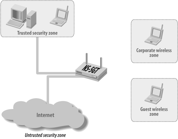
In this recipe, you will first configure the SSID for each user profile, with SSID corp for the corporate users, and SSID guest for the guest users. Figure 3-27 shows the topology of our example.
Typically, corporate users have their systems provided by internal IT and are preconfigured for the network resources. Although there are multiple ways to authenticate the corporate user connection, in this example, we are only showing how to configure WPA-PSK as the authentication type and are assuming that the preshared secret is configured by the internal IT team (the user does not know the preshared secret to keep the key secure).
The basic configuration entails creating the SSID name and defining its properties. In this example, we defined the SSID as corp, and the authentication type as WPA-PSK, with the encryption type as auto (the end user can choose to use AES or TKIP), and bound the corp SSID to the wireless0 interface. We also enabled client isolation on this SSID to prevent users from peer-to-peer bridging, so they would have to use the security policies to allow this traffic.
Guest users who might be visiting customers or partners would just need to get access to the Internet. We don’t want them to access our internal resources, and we want to separate them from our corporate users. To achieve this goal, we defined a different SSID for them called guest with Open as the authentication type and None as the encryption type, then bound it to the wireless1 interface. Because this is going to be an open connection, and anybody can associate with the AP, we want to put in some restrictions, so we will use the security policy to have some user authentication using webauth. See Recipe 13.5 for more on webauth.
For the guest users, we defined two local authentication users on the firewall, called guest1 and guest2. You can use an external database for these users as well, but for this recipe, we will use the local database.
Now, let’s configure the infrastructure to provide the wireless service on the network.
First, we will assign the wireless interfaces to the zones. We have configured different zones to separate users based on their security requirements. Corporate users will connect to the corp zone and guest users will connect to the guest zone. We assigned the wireless0 interface to the corp zone and the wireless1 interface to the guest zone. Next, we need to define the IP address for these interfaces, so we configured 192.168.2.1/24 for the wireless0 interface and 192.168.3.1/24 for the wireless1 interface. For wireless users connecting to the ethernet0/2 interface, which belongs to the Trust zone, will have the 192.168.4.1/24 IP address. For the interface access, we will use the 192.168.1.35/24 address (the Internet connection belongs to the Untrust zone).
We will enable the DHCP server service on the wireless interface to assign the IP address to the wireless users associating with this AP. Here, we have defined only the basic parameters for the DHCP service, such as the gateway and IP address range. To provide user authentication for guest users, we will enable webauth on the wireless1 interface and use only HTTPS to authenticate. We configured 192.168.3.5 as the webauth IP address, and selected ssl-only as the method to authenticate users. You may also define the banner for these users based on your organization’s security policy.
Lastly, we need to define the security policy to allow traffic flow. So far, we have only configured the user association to the AP, so the end-user traffic will flow only when it matches a security policy. Because we have put different user types in different zones, we have already achieved the goal of separating the user traffic, and users will not be able to communicate across the corp and guest zones. We have defined a security policy ID of 1 for traffic from the Trust zone to the Untrust zone, a security policy ID of 2 and 3 to allow wireless users from the corp and guest zones to send traffic to the interface in the Untrust zone, and a security policy ID of 4 to allow the corporate wireless users to connect to the Trust zone users. The implicit deny policy will drop all other traffic, hence preventing guest wireless users from accessing the Trust and corp users. You may want to restrict these policies further to allow traffic based on your organization’s security policy.
Finally, we need to activate the wireless AP. Always remember to activate changes on the firewall using the exec wlan reactivate command. This is a disruptive command, and users will be disconnected from the AP while the APs are being reconfigured. Anytime you make any changes to wireless configurations, you have to use this command to push configurations to the AP engines on the firewall. The following output is based on how many interfaces you have configured:
	ssg5-> exec wlan reactivate
	wireless0/0 interface change physical state to Down
	wireless0/1 interface change physical state to Down

	Start wireless access point physical initialization...

	Wireless access point physical initialization done
	wireless0/0 interface change physical state to Up
	wireless0/1 interface change physical state to Up
To debug your configuration, you can use the get event command to check whether users are able to associate with the AP. Here’s an example of a user connecting to the corp SSID (if you have any issues, check to ensure that users have the correct pre-shared secret):
	2007-08-22 09:36:31 system notif 00564 Wireless station event: Station
	                                 000cf122bfa2 WPA authentication
	                                 passed, SSID: corp.
	2007-08-22 09:36:31 system notif 00564 Wireless station event: Station
	                                 000cf122bfa2 WPA authentication
	                                 negotiating, SSID: corp.
3.7. Configure Bridge Groups for Wired and Wireless Networks
Problem
You want to configure Bridge Groups for wired/wireless networks to share IP addresses and make the networks seamless.
Solution
Configure the zone that will contain the wired and wireless network and assign bgroup0 to the zone. Also, assign the wired interface and wireless interface to the bgroup0 interface:
	set zone name Corp
	set interface "bgroup0" zone "Corp"
	set interface bgroup0 port ethernet0/6
	set interface bgroup0 port wireless0/0
Then, configure the IP address for the bgroup0 interface and enable DHCP for automatic IP address allocations:
	set interface bgroup0 ip 10.10.10.1/24
	set interface bgroup0 dhcp server service
	set interface bgroup0 dhcp server enable
	set interface bgroup0 dhcp server option gateway 10.10.10.1
	set interface bgroup0 dhcp server option netmask 255.255.255.0
	set interface bgroup0 dhcp server ip 10.10.10.100 to 10.10.10.130
Configure the SSID for the wireless network, and bind the wireless interface to the SSID. Then, activate the wireless configuration:
	set ssid name Secured
	set ssid Secured client-isolation
	set ssid Secured authentication wpa-auto-psk passphrase Secret
	   encryption auto
	set ssid Secured interface wireless0

	exec wlan reactivate
Finally, configure the security policy to allow traffic across zones:
set policy from corp to untrust any any any nat src permit
Discussion
You can use Bridge Groups to combine wired and wireless interfaces at the Layer 2 level and make the network seamless. This feature is supported only in the SSG5 and the SSG20 as of this writing. The traffic between wireless and wired networks is switched by the interface driver, and it is not inspected by the security policy, even if you have client isolation configured on the SSID.
To share the IP subnet between ethernet0/6 and wireless0/0 interfaces, create a zone called Corp which will contain the bgroup0. Then, assign the ethernet0/6 and wireless0/0 interfaces to bgroup0. All the Layer 3 configurations will be done on the bgroup0 interface, and the wireless interface will act as a Layer 2 interface in the group. Configure the IP address 10.10.10.1/24 on the bgroup0 interface, and then enable the DHCP service on the bgroup0 interface. The PC connected on the ethernet0/6 and wireless0/0 interfaces will receive IP address allocations from the same DHCP pool addresses. In this example, we configured the DHCP pool address from 10.10.10.100—10.10.10.130:
	set zone name Corp
	set interface "bgroup0" zone "Corp"
	set interface bgroup0 port ethernet0/6
	set interface bgroup0 port wireless0/0
	set interface bgroup0 ip 10.10.10.1/24
	set interface bgroup0 dhcp server service
	set interface bgroup0 dhcp server enable
	set interface bgroup0 dhcp server option gateway 10.10.10.1
	set interface bgroup0 dhcp server option netmask 255.255.255.0
	set interface bgroup0 dhcp server ip 10.10.10.100 to 10.10.10.130
Now, configure the SSID for the wireless network. Create the SSID named Secured with an authentication method using WPA-AUTO-PSK, which will allow WPA and WPA2 users with preshared security to authenticate using the auto encryption type by electing to use AES or TKIP. Now, activate wireless configuration by using the exec wlan reactivate command to push configuration to the wireless AP:
	set ssid name Secured
	set ssid Secured authentication wpa-auto-psk passphrase Secret encryption auto
	set ssid Secured interface wireless0

	exec wlan reactivate
Lastly, configure the security policy to allow traffic based on your network security policy. In this example, we are allowing all traffic from the corp zone to the Untrust zone from any source IP, destination IP, and service. Also, the source IP address will be NAT using the egress interface IP address. Remember that this policy does not control the traffic between the ethernet0/6 and wireless0/0 interfaces. The traffic between the Bridge Group interfaces are switched by the MAC chip on the device, and transit traffic does not reach the CPU for policy inspection.
set policy from corp to untrust any any any nat src permit
You can view the bgroup0 interface using the get interface command. In the following example, bgroup0 shows that eth0/6 and wireless0/0 are assigned to the Bridge Group. The IP address is not configurable on the physical interface once bound to the bgroup:
SSG5->get interfaceA - Active, I - Inactive, U - Up, D - Down, R - Ready Interfaces in vsys Root: Name IP Address Zone MAC VLAN State VSD serial0/0 0.0.0.0/0 Null 0017.cb82.38d9 - U - eth0/0 192.168.1.35/24 Untrust 0017.cb82.38c0 - U - eth0/1 0.0.0.0/0 Null 0017.cb82.38c5 - D - eth0/2 0.0.0.0/0 Null 0017.cb82.38c6 - D - eth0/3 0.0.0.0/0 Null 0017.cb82.38c7 - D - eth0/4 0.0.0.0/0 Null 0017.cb82.38c8 - D - eth0/5 0.0.0.0/0 Null 0017.cb82.38c9 - D - wireless0/1 0.0.0.0/0 Null 0017.cb82.38d6 - D - wireless0/2 0.0.0.0/0 Null 0017.cb82.38d7 - D - wireless0/3 0.0.0.0/0 Null 0017.cb82.38d8 - D -bgroup0 10.10.10.1/24 Corp 0017.cb82.38cb - U - eth0/6 N/A N/A N/A - U - wireless0/0 N/A N/A N/A - U -bgroup1 0.0.0.0/0 Null 0017.cb82.38cc - D - bgroup2 0.0.0.0/0 Null 0017.cb82.38cd - D - bgroup3 0.0.0.0/0 Null 0017.cb82.38ce - D - vlan1 0.0.0.0/0 VLAN 0017.cb82.18cf 1 D - null 0.0.0.0/0 Null N/A - U 0 SSG5->
You can view the wireless interface properties by using the get interface wireless0 command. In this example, the wireless AP 2.4G radio and the SSID are secure:
SSG5->get int w0Interface wireless0/0: description wireless0/0 number 21, if_info 8568, if_index 0 link up, phy-link up member of bgroup0 vsys Root, zone Null, vr untrust-vr *ip 0.0.0.0/0 mac 0017.cb82.38d5wireless AP 2.4G radio mac 0017.cb82.38e0 ssid is Securedpmtu-v4 disabled .... <Output omitted>
You can view the port binding and status using the get interface bgroup0 command, as shown here:
SSG5->get int b0Interface bgroup0: .......... <Output Omitted>> Physical port information:ethernet0/6 is up, full duplex, speed is 100mbps wireless0/0 is up
You can view the client association to the physical interface using the get interface wireless0 association command. In the following example, you can see the wireless association from the PC with the MAC address 0019d2c8d250:
	SSG5-> get int w0 ass
	index   mac address      state    encryption    mode
	=====================================================
	1       0019d2c8d250     assoc    on            11g
	=====================================================
	SSG5->
You can also view the mac-table for bgroup0 using the get interface bgroup0mac-table command; however, this command will show the mac-table for wired physical interfaces only. You will have to use the get int w0 ass command to check the wireless interface associations. In the example, we used mac-table entries for the ethernet0/6 interface:
	SSG5-> get int bgroup0 mac-table
	This command will not show the mac-table for wireless interfaces.
	Interface         MAC Address
	************************************
	ethernet0/6       0015c5785eff

	************************************