
Chapter 5. Transparent Mode
5.0. Introduction
In transparent mode, the firewall acts like a transparent bridge. Although there are historically other switch types, all Ethernet switches are considered transparent bridges. The difference between other switch types (such as token ring or cell switches) and Ethernet switches is that the latter do not maintain path information or even use a configured forwarding table or dynamic path discovery protocol.
Ethernet uses Media Access Control (MAC) addressing in a way that is similar to how IP packets use IP addresses. A MAC address is 48 bits long, whereas an IPv4 address is 32 bits long. MAC addresses on Ethernet are identical, with serial numbers on network interface cards (NICs), also called ports. Each port has its own MAC address, which sometimes can be changed, but rarely is. Ethernet switches became so successful because they work on a very simple principle: when an Ethernet frame enters a switch, the switch puts the src-mac address into a forwarding table, linked to the ingress port. Then it checks to see whether it has a forwarding entry for the dst-mac address to an egress port. If it does not, it floods the packet out on all ports except for the port on which it was received. If it does, it floods the frame to only the port to which the forwarding entry points. The forwarding table is transient, and entries are timed out after a few minutes if they are not refreshed.
In contrast to IP addresses, MAC addresses only have significance on a LAN between hosts or routers on the same broadcast domain, which usually means in the same IP network. Broadcast domains and IP networks commonly overlap one to one, although this is not always the case. The rule of thumb says that switches connect hosts within the same broadcast domain, whereas routers connect broadcast domains to each other. Ethernet works on the ISO/OSI link layer and IP works on the network layer. Ethernet switches do not change the MAC address or any other part of the frame. They are therefore called transparent.
ScreenOS in transparent mode works just like an Ethernet switch. The biggest difference between ScreenOS and a modern multilayer switch is that ScreenOS can either switch or route a packet, but it cannot do both at the same time. ScreenOS also has limited support for virtual local area networks (VLANs). VLANs simulate multiple virtual bridges within an Ethernet switch, maintaining separate forwarding tables for each VLAN. VLAN membership is indicated within an Ethernet frame by a tag in a header extension.
Ethernet switches switch Ethernet frames, although many multilayer switches are also IP-aware. Multiple different types of Ethernet frames exist, from connectionless and connection-oriented, to unicast, multicast, and broadcast. The most significant bit in the MAC address indicates whether a frame is a unicast or multicast/broadcast frame. ScreenOS supports all three types.
IP runs over connectionless Ethernet-II frames and unicast, multicast, and broadcast addresses are mapped to their MAC counterparts. Network layer packets are signaled in the Ethernet-II frame by an EtherType. IP has an EtherType of 0x0800 and the Address Resolution Protocol (ARP) has an EtherType of 0x0806. ScreenOS considers these as IP traffic, versus non-IP traffic such as frames carrying IPX Protocol Data Units (PDUs).
ScreenOS acts like an Ethernet switch by forwarding frames, but it applies access policies as well as virtual private network (VPN) policies in addition to application layer attack signatures on the network layer, transport layer, and application layer. ScreenOS policies do not control Ethernet frames, but rather the encapsulated IP packets inside.
In Figure 5-1, you can see an example of a data packet containing the Ethernet, IP, and User Datagram Protocol (UDP) headers as well as the payload. In transparent mode, the firewall switches on the dst-mac and in route mode it routes on the dst-ip address. On the right side, you can see the security features the firewall applies and where it does so. The security features in ScreenOS are pretty much identical whether in route or transparent mode. The difference mainly consists of how to integrate the firewall into the topology.
Ethernet uses the Spanning Tree Protocol (STP) to form a loop-free topology. STP forms a tree-like graph from an elected root switch so that the root can be reached from any switch in the most efficient path. Redundant ports are put into blocking mode. STP communicates via Bridge Packet Data Units (BPDUs). Although there are many flavors of STP, the most common are the IEEE 802.1d and the proprietary PVST+ protocol from Cisco Systems. New standards, such as IEEE 802.1s, are becoming more widespread in data networks. ScreenOS does not implement STP, but it is compatible with STP by forwarding BPDUs transparently between STPcapable switches.

5.1. Enable Transparent Mode with Two Interfaces
Solution
Move two interfaces into a Layer 2 (L2) zone, and all other interfaces into the null zone:
	unset interface e0/0 ip
	set interface e0/0 zone v1-trust

	unset interface e0/1 ip
	set interface e0/1 zone v1-untrust
Configure a management address on the virtual vlan1 interface:
	set interface vlan1 ip 192.168.1.100/24
	set route 0.0.0.0/0 interface vlan1 gateway 192.168.1.254
Then, configure a policy:
set policy from v1-untrust to v1-trust any any http permit
Discussion
You enable transparent mode by putting interfaces into L2 zones. There are two pre-defined L2 zones: V1-Trust and V1-Untrust. Do not confuse those with the L3 (Layer 3) zones Trust and Untrust when you create policies in the WebUI or CLI. Note that the NetScreen Security Manager (NSM) does not differentiate between L2 zones and L3 zones, so policy bases can be shared between devices in transparent and route modes.
Both zones will be in the same VLAN, with the firewall acting like a bridge. To enable transparent mode, attach L2 zones to interfaces. Do not forget to unset any IP addressing. Move all other interfaces into the null zone. Before you move the interfaces to the L2 zones, the firewall is in Network Address Translation (NAT) or route mode (by factory default, some firewall models are already in transparent mode):
FIREWALL->get system | include ^SystemSystem in NAT/route mode. FIREWALL->unset interface e0/0 ipFIREWALL->set interface e0/0 zone v1-trustFIREWALL->unset interface e0/1 ipFIREWALL->set interface e0/1 zone v1-untrustFIREWALL->set int e0/2 zone NullChanged to pure l2 mode FIREWALL->get system | include ^SystemSystem in transparent mode.
Configure an IP address on the vlan1 interface and a default route:
	set interface vlan1 ip 192.168.1.100/24
	set route 0.0.0.0/0 interface vlan1 gateway 192.168.1.254
You can use the vlan1 interface for in-band management, for monitoring with track-ip, with management protocols such as SNMP traps and Syslog, and to terminate VPN tunnels, which are also supported in transparent mode. You cannot run dynamic routing protocols on a firewall in transparent mode because the firewall will only act as a host. It will not use the routing table to decide how to switch packets through the firewall. It will use the routing table only for packets originating from the firewall.
Figure 5-2 shows a typical transparent mode design.
The firewall is positioned between a router and a switch. Hosts are connected to the switch. The switch is connected to the firewall via an access link and the firewall to the router via an access link. All hosts in this recipe are in the same network, 192.168.1.0/24. The default gateway of the hosts is the router’s interface, 192.168.1.254. The firewall has the vlan1 interface in the same network for in-band management.

The default route for the firewall is also the router’s interface, 192.168.1.254. The firewall’s routing table is not used for forwarding traffic between the router and the host.
If a host wants to communicate with a different network, it sends an ARP request for the router’s interface address, 192.168.1.254. The firewall is forwarding this request unchanged as an Ethernet frame with EtherType 0x0806. The router will reply and the firewall will again forward this reply. The firewall is able to build its forwarding table from the src-mac address of the ARP frames. ScreenOS calls the Layer 2 forwarding table a Forwarding Information Base (FIB), whereas other vendors may call it Content Addressable Memory (CAM). The host now knows the MAC address of its default gateway, and the firewall knows behind which interfaces the host and the router are located. If the forwarding table entry times out, the firewall will relearn it from the next frame being sent by the host or router. When the routers send traffic back to the host, the host will also ARP for its MAC address and the firewall will forward that request. With the first IP packet being sent by the host, the firewall builds session state. When the server, or another host somewhere beyond the router, replies to the first host, an Ethernet frame is received from the router, and the firewall matches the encapsulated IP packets (EtherType 0x0800) toward the existing session and forwards the frame. The firewall will not change the header of the Ethernet frame. If a policy or signature denies traffic, the Ethernet frame is dropped the same way as when the IP packet is dropped in route mode.
It is also possible to position the firewall between two routers, which is often done when protecting wide area network (WAN) links. If the firewall is placed between an Internet gateway router and an internal router, you need at least two “usable” public IP addresses for that segment: one for the internal router and one for the in-band management of the firewall.
5.2. Enable Transparent Mode with Multiple Interfaces
Solution
First, configure custom security zones:
	set zone name l2-trust-1 L2
	set zone name l2-trust-2 L2
	set zone name l2-trust-3 L2

	set interface e0/1 zone v1-untrust
	set interface e0/2 zone l2-trust-1
	set interface e0/3 zone l2-trust-2
	set interface e0/4 zone l2-trust-3
Then, configure a management address on the virtual vlan1 interface:
	set interface vlan1 ip 192.168.1.100/24
	set route 0.0.0.0/0 interface vlan1 gateway 192.168.1.254
Now, configure the policies:
	set policy from v1-untrust to l2-trust-1 any any http permit
	set policy from l2-trust-1 to l2-trust-2 any any ssh permit
Discussion
You can create custom zones in addition to the predefined zones, V1-Trust and V1-Untrust. Custom zones receive the mandatory prefix of L2, similar to the prefix V1 in the predefined zones:
set zone name l2-myzone L2
The same rules apply here as for designs with only two interfaces (see Recipe 5.1): all interfaces are in the same broadcast domain; unused interfaces have to be moved to the null zone to enable transparent mode; hosts cannot be assigned to different IP networks; and all interfaces connected to the firewall are in access mode. The fire-wall can do either routing or switching but not both at the same time, and in trans-parent mode the firewall acts as a flat bridge. The in-band vlan1 management interface’s IP address is in the same IP network as hosts behind all interfaces.
	set interface vlan1 ip 192.168.1.100/24
	set route 0.0.0.0/0 interface vlan1 gateway 192.168.1.254
This topology is a useful design where a large server segment needs to be partitioned into security zones. Policies can be written that protect each custom zone from v1-untrust and v1-trust from each custom zone, as well as protect custom zones from each other:
	set policy from v1-untrust to l2-trust-1 any any http permit
	set policy from l2-trust-1 to l2-trust-2 any any ssh permit
Figure 5-3 shows such a sample network. The firewall uses four interfaces, one in v1-untrust and three in custom zones: l2-trust-1, l2-trust-2, and l2-trust-3. Each interface connects to a physical switch or an access port in a different VLAN on an access layer switch.

In this design, the general rule “one VLAN maps to one IP address” does not necessarily apply. Technically, all Layer 2 segments connected to the firewall build one broadcast domain and all hosts are in the same IP network. But all hosts and all interfaces on the firewall may be connected to the same switch separated only by VLANs. The switch is connected via access ports to the firewall, and the firewall would bridge rather than route between the VLANs. Some switches apply a discovery protocol such as Cisco Systems’ Cisco Discovery Protocol (CDP), which may discover a loop when bridging VLANs on the same switch and error-disable the associated port. Those protocols need to be disabled on the ports connected to the fire-wall to make this design work. The topology in itself is hierarchical and loop-free. Note that it is also possible to use different physical switches instead of VLANs on the same switch.
Hosts that are within such a LAN or VLAN connect directly to each other without passing through the firewall—when a host connects to another host in a different LAN or VLAN, it passes the firewall, and the firewall does a policy lookup and applies whatever other security was configured. Only when a host connects to another host in a different IP network will traffic pass the router behind the V1-Untrust zone. Make sure that only the VLAN, connected to V1-Untrust, has an L3 virtual interface configured. When hosts in the same network behind different security zones talk to one another, the firewall switches the Ethernet frame directly, as any other Ethernet switch would.
5.3. Configure a VLAN Trunk
Problem
You want to put the firewall into a trunk and pass VLAN tagged frames.
Solution
Configure the firewall to ignore the VLAN tag while matching on the IP header on policies:
set interface vlan1 vlan trunk
Move two interfaces into a Layer 2 (L2) zone, and all other interfaces into the null zone:
	unset interface e0/0 ip
	set interface e0/0 zone v1-trust

	unset interface e0/1 ip
	set interface e0/1 zone v1-untrust
Configure a management address on the virtual vlan1 interface:
	set interface vlan1 ip 192.168.1.100/24
	set route 0.0.0.0/0 interface vlan1 gateway 192.168.1.254
set policy from v1-untrust to v1-trust any any http permit
Discussion
A server network should be secured, but addressing cannot be changed on the servers if it is hardcoded into applications. The easiest way to introduce a firewall is to put the firewall into transparent mode and include it between the servers and the next-hop router. However, servers are commonly connected to different VLANs.
In Figure 5-4, a firewall is introduced between the access layer switch and the distribution layer switch. The access layer switch is a Layer 2 device, and the distribution layer switch is usually a multilayer switch; hence, it supports virtual L3 VLAN interfaces. Multiple VLANs are configured for different servers. An 802.1Q trunk connects the access layer switch with the distribution layer switch. This is a typical data center design. The motivation for such a design is that the firewall should not interfere with the network topology.
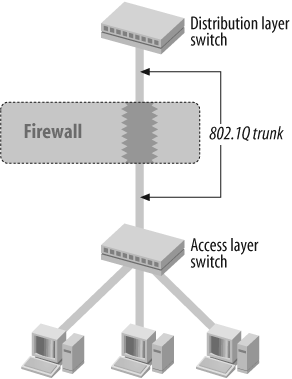
Both ports from the switches connecting to the firewall are configured in trunk mode; however, the firewall’s interfaces are configured in access mode. In classic transparent mode, ScreenOS does not support trunk ports (see Recipe 5.4). However, it is possible to configure ScreenOS to simply ignore the IEEE 802.1Q subhead while doing policy checking; in this case, the firewall would be truly transparent to the topology as it does not change the Ethernet frame, and rather just shifts policy matching two bytes to the right to account for the added VLAN subheader.
The following configures ScreenOS to ignore VLAN tags on the vlan1 management interface:
set interface vlan1 vlan trunk
Two interfaces are placed into L2 zones as described in Recipe 5.1:
	unset interface e0/0 ip
	set interface e0/0 zone v1-trust

	unset interface e0/1 ip
	set interface e0/1 zone v1-untrust
Configure a management address on the virtual vlan1 interface. The vlan1 interface ends up in the “native” or uncolored VLAN. This is the default VLAN on which the switch accepts untagged frames. It is used for management functions.
	set interface vlan1 ip 192.168.1.100/24
	set route 0.0.0.0/0 interface vlan1 gateway 192.168.1.254
Then, configure a policy:
set policy from v1-untrust to v1-trust any any http permit
The design shown in Figure 5-5 can be useful when only some servers should be protected; for example, because of compliance rules. In this case, a second access layer switch could be introduced. The servers that should not be protected connect to the first access layer switch, and the servers that should be protected connect to a new access layer switch. The two switches are again connected via a VLAN trunk with the firewall in the middle. The first access layer switch is connected to its distribution layer switch.

ScreenOS is compatible with 802.1Q trunking, but not with the proprietary trunking Inter Switch Link (ISL) protocol. ISL tagged traffic may be globally permitted or globally denied as non-IP traffic, but it is not possible to define policies for ISL trunked traffic. It is advisable to manually configure switches to use IEEE 802.1Q and to not use ISL or any other proprietary trunk encapsulation. Older Cisco Systems switches often default to ISL trunking, which by default would be permitted without a policy on ScreenOS.
To permit ISL tagged frames through the firewall, configure this:
	set interface vlan1 bypass-non-ip
	unset interface vlan1 bypass-non-ip
This command sequence may be slightly counterintuitive. The first line enables non-IP frames through the firewall and the second denies non-IP unicast frames, leaving non-IP multicast frames. To deny ISL tagged frames through the firewall, configure this:
unset interface vlan1 bypass-non-ip-all
As both ISL and STP use non-IP multicast frames, denying ISL in ScreenOS also denies STP frames.
Because of the shared FIB on ScreenOS, it is very important to make sure that destination MAC addresses of all devices in any VLAN passing the firewall are unique—in particular, if multiple trunks are running through the same firewall concurrently and you are using ScreenOS 5.4 or earlier. Some switches support more than 1,024 VLANs and use a MAC address mapping scheme to support more than the 10 bits in the IEEE 802.1Q tag. MAC addresses of router interfaces on those multilayer switches usually cannot be configured and are automatically assigned from the pool of burned-in addresses (BIAs). The use of the Hot Standby Router Protocol (HSRP) or Virtual Redundancy Router Protocol (VRRP) in that case makes sense, even if there is only one router in the VLAN to guarantee unique destination MAC addresses. Each HSRP or VRRP group uses a unique MAC address. To keep it simple, it is recommended to run just one trunk through the same firewall or the same Virtual System (VSYS) so that there is not the possibility of seeing the same MAC address behind multiple interfaces.
5.4. Configure Retagging
Solution
Choose two interfaces on the switch and make them both trunks. Configure the firewall to rewrite VLAN tags from one interface to the other.
First, create a vlan group for vlan-100:
	set vlan group name vlan-100
	set vlan group vlan-100 100 100
Then, link the vlan group to the two interfaces:
	set vlan port e2/1 group vlan-100 zone v1-trust
	set vlan port e2/2 group vlan-100 zone v1-untrust
Retag vlan-100 to vlan-200 and attach to interface e2/1:
	set vlan retag name map-100-to-200 100 200
	set vlan port e2/1 retag map-100-to-200
Then, configure policies:
	set policy from v1-untrust to v1-trust any any http permit
	set policy from v1-trust to v1-untrust any any ssh permit
Discussion
In some instances, it may be desirable to integrate a firewall with a multilayer switch which would perform switching and routing. All the ports on the switch can be made virtual firewall ports and the administrator can configure which VLANs are sent through the firewall and which bypass the firewall. VLAN retagging is supported on ScreenOS 6.0 and later only on the NS-5000 Series platform.
The way to accomplish this integration is by connecting the switch via two trunked links to the firewall. Each trunk transmits Ethernet frames, sorted by VLAN tags. The firewall in between is switching the Ethernet frames from one interface to another interface; this creates a loop because the switch would send a frame with, say, vlan-100 to the firewall, the firewall would send it back on the second interface to the switch, and the switch would send it back to the firewall, and so forth. To break this loop, the firewall needs to “mark” frames that have passed the firewall.
A simple way to do this “marking” is to swap the tag. The switch would send an Ethernet frame with VLAN tag 100 to the firewall, and the firewall would check the embedded packet against its policy table and other higher-security layers and, if permitted, send it on to the switch. But this time, the firewall retags the Ethernet frame with a different tag—for instance, vlan-200—so that no loop can be created. The swap of the VLAN tag does not make a difference for edge ports (the opposite of trunk ports) because on those ports, the tag is stripped anyway. However, it will make a difference if the switch downstream of the firewall connects to other switches via a trunk.
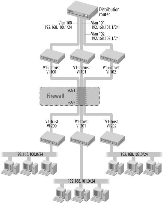
Figure 5-6 shows a typical retagging topology.
In the middle of the topology is the firewall. On top of the firewall are three logical switches; the bottom of the firewall also has three logical switches. Those logical switches are VLANs within the same multilayer switch. At the top is a router, which is also a routing engine within the same multilayer switch. The router connects via virtual VLAN interfaces to the top VLANs. The firewall is actually connected via two trunk interfaces to the switch and not via individual physical interfaces. This is essential for this design. There is one trunk on interface e2/1 on the top carrying vlan-100, vlan-101, and vlan-102, and there is another trunk on interface e2/2 on the bottom carrying vlan-200, vlan-201, and vlan-202. The firewall in the middle retags vlan-100 to vlan-200, vlan-101 to vlan-201, and vlan-102 to vlan-202. Notice that the firewall works in transparent mode. The firewall is actually not routing packets, but switching them, and itself works like a switch. The firewall will keep the VLANs separate from each other, and only allows communication between the main VLAN and its retag partner VLAN.
To configure the topology, first create a VLAN group for all vlans:
	set vlan group name my-vlans
	set vlan group my-vlans 100 102
Then, link the vlan group to the two trunk interfaces. You must also configure which of the trunk interfaces is in the v1-untrust zone and which is in the v1-trust zone:
	set interface e2/1 zone null
	set interface e2/2 zone null
	set vlan port e2/1 group my-vlans zone v1-untrust
	set vlan port e2/2 group my-vlans zone v1-trust
Configure retagging for the VLANs, and attach the retag group to interface e2/2:
	set vlan retag name my-vlan-map
	set vlan retag my-vlan-map 100 200
	set vlan retag my-vlan-map 101 201
	set vlan retag my-vlan-map 102 202
	set vlan port e2/2 retag my-vlan-map
Finally, configure the policies:
	set policy from v1-untrust to v1-trust any any http permit
	set policy from v1-trust to v1-untrust any any ssh permit
5.5. Configure Bridge Groups
Problem
You need to put several devices into the same IP network and broadcast domain, but you do not want to deploy an extra switch.
Solution
Put the interfaces into a Bridge Group:
	set interface bgroup0 zone "Trust"
	set interface bgroup0 port ethernet0/1
	set interface bgroup0 port ethernet0/2
	set interface bgroup0 port ethernet0/3
	set interface bgroup0 port ethernet0/4
	set interface bgroup0 port ethernet0/5
	set interface bgroup0 port ethernet0/6
Discussion
Concurrent Route Bridging (CRB) is used by routers where some interfaces bridge to each other and some interfaces route among each other. Such a feature is a relic from the times when you had to run several different networks and transport layer protocols concurrently, and some protocols did not deploy the concept of networks and hence could not be routed. Today, IP is the dominant network layer protocol. Though it is possible to configure some interfaces in route mode and others in transparent mode, this is not a supported design. Integrated Route Bridging (IRB) occurs when, in addition to routed interfaces and switched interfaces, there are also virtual L3 interfaces that support routing between switched and routed interfaces. Today, this design is widely adopted on enterprise switches.
Implementing route bridging in a security device is more challenging because security policies are applied to traffic streams crossing interfaces and security zones. Rather than mixing route mode and transparent mode, ScreenOS implements IRB with the help of Bridge Groups combined with interfaces, usually in route mode. Bridge Groups are a collection of interfaces you can group together into a broadcast domain. ScreenOS switches Ethernet frames within members of a Bridge Group rather than routing IP packets. This is implemented via switch ASICs on the SSG Series and special Ethernet Physical Interface Modules (PIMs). The virtual Bridge Group interface, called bgroup, is the edge to the security features of ScreenOS. There are no security features between ports within a Bridge Group. This architectural approach is very similar to connecting a standalone switch to a port on the firewall.
There are two important use cases for Bridge Groups. The first is in a small-office setup such as that illustrated in Figure 5-7, where hosts can be directly connected to the firewall instead of having to deploy a separate desktop switch.

In Figure 5-7, several computers are connected to a Bridge Group. The Bridge Group is in the Trust zone. The firewall also has one interface in the Untrust zone, which connects upstream to an Internet access router:
	set interface ethernet0/0 zone "Untrust"
	set interface bgroup0 zone "Trust"
	set interface bgroup0 port ethernet0/1
	set interface bgroup0 port ethernet0/2
	set interface bgroup0 port ethernet0/3
	set interface bgroup0 port ethernet0/4
The second important use case for Bridge Groups is with high availability (HA) topologies. With the NetScreen Redundancy Protocol (NSRP), as with HSRP or VRRP, all participating interfaces need to be in a broadcast domain. Traditionally, those networks were built by placing the firewalls like a sandwich between switches on the Trust and Untrust sides of the firewall, as shown in Figure 5-8.
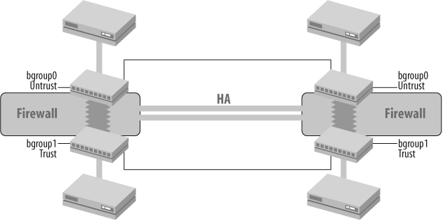
In Figure 5-8, the two interfaces of the firewalls on the Untrust side and the two routers are all in the same broadcast domain. The routers’ interfaces would be put into an HSRP or VRRP group, and the interfaces on the firewall would be in a virtual security device (VSD) group. There would be an identical setup for the Trust side and any other interface with directly connected routers. Do not confuse on-the-fire-wall Bridge Groups with HA interfaces because Bridge Groups build broadcast domains. NSRP does not actually exchange HA messages over payload interfaces, unlike HSRP and VRRP. ScreenOS uses dedicated HA interfaces for this purpose because on a firewall, a lot more information is being exchanged for HA than in HSRP or VRRP. Payload interfaces have to be in the same broadcast domain so that all devices on this broadcast domain can reach each other’s virtual IP address. Therefore, all devices need to be in the same network and need to be able to ARP for each other’s IP addresses.
	set interface bgroup0 zone "Untrust"
	set interface bgroup0 port ethernet0/0
	set interface bgroup0 port ethernet0/1

	set interface bgroup1 zone "Trust"
	set interface bgroup1 port ethernet0/2
	set interface bgroup1 port ethernet0/3
Although Bridge Groups are more commonly configured in route mode, you can configure them in route mode and transparent mode by placing them into an L3 or L2 zone. The first good example of why somebody would want to configure the firewall in transparent mode and use, in addition, a Bridge Group would be for a small-office setup. In this example, however, the hosts don’t have to be protected from each other, but they do have to be protected from hosts on the Internet. Often, it is easier to deploy a firewall in transparent mode in such a small deployment so that access routers do not need to be reconfigured. Therefore, two zones are enough for developing policies on the firewall. It is just easier to connect a few hosts directly to the firewall instead of provisioning an additional switch.
	set interface ethernet0/0 zone "V1-Untrust"
	set interface bgroup0 zone "V1-Trust"
	set interface bgroup0 port ethernet0/1
	set interface bgroup0 port ethernet0/2
	set interface bgroup0 port ethernet0/3
	set interface bgroup0 port ethernet0/4
5.6. Manipulate the Layer 2 Forwarding Table
Solution
Show the content of the FIB:
get mac-learn
Delete the FIB:
clear mac-learn
Delete an entry in the FIB:
unset mac 0010db123456 [ vlan 1 ]
Add a static entry to the FIB:
set mac 0010db123456 interface e0/1 [ vlan 1 ]
Discussion
Similar to a route table, a switch also has a forwarding table. Transparent bridges, a category to which all Ethernet switches belong, do not run a routing or discovery protocol. They populate the forwarding table on the fly by mapping src-mac addresses to incoming interfaces. Then, when a frame is switched, the switch just looks up the dst-mac address and forwards the frame out to the interface, which it has saved in its forwarding table. If there is no table entry, the switch forwards the frame out to all interfaces except for the interfaces on which it was received. ScreenOS 6.0 and later maintains one forwarding table for each VLAN separately, whereas earlier releases have only one table because there was no VLAN awareness. ScreenOS’s forwarding table is termed a FIB, whereas other vendors may call it a CAM table. Do not confuse the FIB table with the ARP table, which is used in transparent mode only for traffic originating from the firewall.
You can also switch ScreenOS from a transparent bridge to a bridge with static forwarding entries. In this mode, however, it is mandatory to configure static forwarding table entries for all hosts and routers connected to that broadcast domain:
	unset interface vlan1 broadcast
	unset mac-learn
	set mac 0010db123456 e0/1 vlan 1
Alternatively, you can also populate the forwarding table with the help of ARPs and trace routes. The firewall ARPs for each destination address if the IP address is in the same network as its vlan1 IP address or sends a traceroute. The reply is encapsulated in an Ethernet frame from which ScreenOS learns the location of the destination or next-hop MAC address:
set interface vlan1 arp trace-route
Both alternatives are rarely used, but keep in mind that MAC addresses have significance only on the LAN or VLAN; hence, the broadcast domain. The LAN to which the firewall is connected is usually in a secure location, but if multiple servers are connected to that broadcast domain and a server is penetrated, it is possible to poison the forwarding table of the firewall and create a Denial of Service (DoS) attack or redirect traffic. So, if a design with a static FIB table is chosen, a static table entry for each host and router on the broadcast domain needs to exist.
5.7. Configure the Management Interface in Transparent Mode
Solution
First, enable Secure Shell (SSH) and SSL:
	set ssh enable

	set ssl enable
Configure in-band management:
	set interface vlan1 ip 192.168.1.100/24
	set interface vlan1 manage
	set interface vlan1 nsrp manage zone v1-trust

	set route 0.0.0.0/0 interface vlan1 gateway 1.1.1.1
Alternatively, configure out-of-band management:
	set interface e0/0 zone mgt
	set interface e0/0 ip 192.168.1.100/24

	set route 10.0.0.0/8 interface e0/0 gateway 192.168.1.254
Then, allow management access from certain interfaces:
	set interface e0/0 manage ssh
	set interface e0/0 manage ssl
	set interface e0/0 manage ping
Optionally, you can configure which hosts will manage the firewall:
set admin manager-ip 10.1.1.100
Discussion
You can manage the firewall in-band or out-of-band. The default is in-band.
You have to apply management settings at interfaces as well as on the virtual vlan1 interface. Some ScreenOS devices have a dedicated MGT port, and in other devices any port can be moved into the MGT zone and can become a dedicated management port. WebAuth and VPN in transparent mode work only through the vlan1 virtual interface and do not work with an out-of-band management interface. You can manage an NSRP member in backup mode only through one zone, which is configurable.
The following enables SSH and SSL globally on the firewall:
	set ssh enable

	set ssl enable
On ScreenOS 5.1 and earlier, you will have to install your own SSL certificate. (For more information, see Chapter 10.)
	get pki x509 list local-cert

	set ssl cert 0x1
In this recipe, the firewall should be managed in-band, with v1-trust as the preferred management zone for a backup NSRP member. You want to enable SSH, SSL, and ping. If the firewall is configured differently from the default, deny all management access to the vlan1 interface first, and then enable selected management protocols on interfaces (by default, interfaces in different zones allow a different set of management protocols). It is a good practice to first switch off all management on an interface so that only selected management protocols are enabled. The vlan1 interface needs to have an IP address in the VLAN (which is active on both sides of the firewall):
	set interface vlan1 ip 192.168.1.100/24
	set interface vlan1 manage
	set interface vlan1 nsrp manage zone v1-trust

	unset interface e0/0 manage
	set interface e0/0 manage ssh

	set interface e0/0 manage ssl
	set interface e0/0 manage ping

	set route 0.0.0.0/0 interface vlan1 gateway 192.168.1.254
Tip
Notice that the places where management is configured for ScreenOS change with releases, with some older releases requiring you to enable management on an interface as well as on the L2 zone or a virtual L2 interface:
	set zone v1-trust manage
	set interface v1-trust manage
Those commands may still be present, hidden in the CLI of the more recent releases, and if changed, they can cause unexpected problems.
You can also manage the firewall through a dedicated interface. If a dedicated interface is chosen in transparent mode, the routing table will be shared with the vlan1 interface, which will still be used by VPN, WebAuth, or track-ip. You cannot configure a default route out of an out-of-band management interface and the vlan1 interface at the same time.
	set interface e0/0 zone mgt
	set interface e0/0 ip 192.168.1.100/24
	set interface e0/0 manage telnet
	set route 10.0.0.0/8 interface e0/0 gateway 192.168.1.254
When the firewall is within a trunk, and it is managed via the vlan1 interface or VPN and WebAuth should be used, managed traffic will be sent and received from the native or default VLAN that is able to switch untagged frames. The native VLAN is also called untagged VLAN or uncolored VLAN (in a switch, usually any VLAN can be made the native VLAN on a perport basis). Make sure you take STP and other Layer 2 management protocols such as CDP and the VLAN Trunk Protocol (VTP) into account, which also use the native or default VLAN. In addition, you can also restrict which hosts can manage the firewall:
set admin manager-ip 10.1.1.100
5.8. Configure the Spanning Tree Protocol (STP)
Problem
You want to configure STP with ScreenOS in transparent mode.
Solution
ScreenOS does not support STP, but it is able to forward STP BPDUs so that the spanning tree can operate through the firewall using the following:
	set interface vlan1 bypass-non-ip
	unset interface vlan1 bypass-non-ip
Discussion
Although ScreenOS cannot participate in STP, spanning tree BPDUs can pass through the firewalls, and bridges on either end are able to participate in the tree.
The following permits or denies STP through the firewall:
	set interface vlan1 bypass-non-ip
	unset interface vlan1 bypass-non-ip
The first line enables unicast and multicast non-IP frames through the firewall, and the second denies non-IP unicast frames, leaving non-IP multicast frames. With this odd command sequence, get interface vlan1 should show the following:
bypass non IP: multicast
You do not have to run STP with NSRP. Running STP can speed up convergence in certain switch topologies because STP forces FIB aging timers to decrease to a period of usually a few seconds after a topology change was detected. Without STP, convergence after a failover may take up to the current value of the FIB aging timer, which is usually about several minutes for active flows. FIB table aging is independent of tuning NSRP parameters because it does not impact topology convergence within upstream or downstream switches.
STP BPDUs will be flooded out to all interfaces. As long as all VLANs are following the same STP tree through the firewall interfaces, or BPDUs are distinctive between trees, this behavior does not cause any problems. STP comes in many flavors: PVST+ will tag BPDUs with the VLAN tag, and IEEE 802.1s hashes regional information from the BPDU to discriminate between trees and, therefore, should work, too. Certain IEEE 802.1D proprietary Multiple Spanning Tree (MST) extensions that support unique trees for each VLAN could cause problems.
5.9. Enable Compatibility with HSRP and VRRP Routers
Problem
You have HSRP or VRRP routers on a LAN, which is connected to the firewall. Switches on the other side of the firewall do not learn the location of the virtual IP and keep on flooding frames to the VIP out to all interfaces.
Solution
Create a policy to permit HSRP Hello messages:
	set address v1-trust hsrp 224.0.0.2/32
	set service hsrp protocol udp src-port 1985-1985 dst-port 1985-1985
	set policy top from v1-untrust to v1-trust any hsrp hsrp permit
Create a policy to permit VRRP Hello messages:
	set address v1-trust vrrp 224.0.0.18/32
	set service vrrp protocol 112 src-port 0-65535 dst-port 0-65535
	set policy top from v1-untrust to v1-trust any vrrp vrrp permit
Discussion
Ethernet frames, originating from HSRP routers, are sourced from the physical MAC address of each router’s interface. Ethernet frames from a VRRP router should be sourced by the virtual MAC address, but not all vendors may implement it this way. An ARP request to an HSRP or VRRP virtual IP address will be replied to with the virtual MAC address so that hosts are sending traffic to the active group member. Transparent switches build their forwarding table by listening to the src-mac address in a frame. Without a FIB or CAM table entry for the virtual MAC address, a switch is flooding frames directed toward the virtual IP address out to all interfaces except the interface on which it was received. For the switch to be able to learn the location of the virtual MAC address, which may never exist in the source of a payload frame, the active HSRP and VRRP router sends Hello messages with the virtual MAC address in the source.
Blocking HSRP or VRRP messages in the firewall denies downstream switches to learn the location of the active router. The consequence is that downstream switches will flood traffic, directed to those routers, out of all interfaces instead of to the forwarding firewall. Because every device on that VLAN will receive every IP packet—directed to another subnet—from every other device on that VLAN, the network stack on servers may get overloaded. For example, CPU exhaustion may be caused on an NSRP firewall in backup mode because in backup mode the firewall drops all traffic not directed to its management interface instead of setting up a session and switching the traffic. Furthermore, dropping of packets in backup mode is resource-intensive and can cause high CPU use on the backup NSRP device, in particular on high-performing ASIC platforms.
To allow HSRP and VRRP Hello messages to pass the firewall, configure a rule to permit them through the firewall. When the HSRP router is behind v1-untrust and the protected hosts in v1-trust (see Figure 5-2 earlier in this chapter), create the HSRP address object in v1-trust and any other zone, if configured:
	set address v1-trust hsrp 224.0.0.2/32
	set service hsrp protocol udp src-port 1985-1985 dst-port 1985-1985
	set policy top from v1-untrust to v1-trust any hsrp hsrp permit
In the same way, you can configure a VRRP rule from the firewall zone where the routers are located away to all other zones. Although VRRP routers will send gratuitous ARPs to signal a switchover, the firewall rule will ensure that FIB/CAM tables learned from the gratuitous ARPs are refreshed:
	set address v1-trust vrrp 224.0.0.18/32
	set service vrrp protocol 112 src-port 0-65535 dst-port 0-65535
	set policy top from v1-untrust to v1-trust any vrrp vrrp permit
A return policy for Hellos is not required because the Hellos do not actually need to pass the firewall to reach the peer router—they are already exchanged through the broadcast domain to which the two routers are connected. The rule is there only to allow the firewall and switches behind the firewall to learn the location of the active router.
You could also configure a global policy, which would be processed after all interzone rules were processed, and is valid for all zone combinations:
	set address global hsrp 224.0.0.2/32
	set service hsrp protocol udp src-port 1985-1985 dst-port 1985-1985
	set policy top global any hsrp hsrp permit

	set address global vrrp 224.0.0.18/32
	set service vrrp protocol 112 src-port 0-65535 dst-port 0-65535
	set policy top global any vrrp vrrp permit
5.10. Configure VPNs in Transparent Mode
Solution
Configure a policy-based VPN, and anchor the tunnel on the vlan1 interface:
	set ike gateway "gateway-b" ip 192.168.2.100 outgoing-zone
	"V1-Untrust" preshare juniper sec-level standard
	set ike gateway "gateway-b" nat-traversal

	set vpn "gateway-b" gateway "gateway-b" sec-level standard
	set vpn "gateway-b" monitor optimized rekey
Then, configure a tunnel policy, referencing L2 zones:
	set policy id 1 from "V1-Trust" to "V1-Untrust" "192.168.1.0/24"
	"192.168.2.0/24" "ANY" tunnel vpn "gateway-b" log
	set policy id 2 from "V1-Untrust" to "V1-Trust" "192.168.2.0/24"
	"192.168.1.0/24" "ANY" tunnel vpn "gateway-b" log
Discussion
An often-asked question is whether a VPN can be used to bridge a network between firewalls. The answer is “not really” because a VPN does not forward ARP queries via the IP Security (IPSec) tunnel. (You can, however, bridge networks over the tunnel if the two firewalls are directly connected via the same L2 link so that ARPs can be exchanged in the clear outside the tunnel.) VPN in transparent mode can still be useful.
To understand how VPN in transparent mode works, one has to understand how policy-based VPN works. With policy-based VPN, a tunnel policy is configured between two zones. If traffic is passing those two zones and it matches the policy, packets are encrypted over the configured VPN tunnel and sent to the configured remote Internet Key Exchange (IKE) gateway. The only difference with transparent mode and route mode is the way packets are switched from the ingress zone to the egress zone. In transparent mode, packets are switched as though on an Ethernet switch rather than routed. This might be confusing because it was said before that VPN on transparent mode cannot bridge networks, but it is why hosts need to have a route for the remote network to point to a router behind the firewall.
Figure 5-9 depicts a simple VPN topology. On the right side is network 192.168.1.0/24, and on the left side is network 192.168.2.0/24. The left and right firewalls are both in transparent mode. The hosts on either end are configured in the same network with their respective routers and point a default route to the router on the other side of the firewall. For example, hosts on the left side have IP addresses in the network of 192.168.1.0/24 and point to 192.168.1.254 as the default gateway—not to the fire-wall’s vlan1 address. This is critical so that hosts send packets through and not to the firewall, where the tunnel policy can catch them before they reach the router.

Between the two firewalls are two routers, which represent the Internet cloud. Fire-walls do not necessarily need to be in transparent mode on both ends. One end could be in transparent mode and the other end could be in route mode. It does not even matter if the other end is also using policy-based VPN or route-based VPN. In the latter case, Security Associations (SAs) and the proxy ID have to match (as detailed shortly).
The configuration of the VPN is not much different than it is in route mode. First, put interfaces into zones and give the vlan1 interface an IP address. The vlan1 interface must be in the same network with the hosts and the local router. Also, create a default route, which is used to route the encrypted portion of the tunnel to the remote gateway.
On the left firewall, configure the following:
	set interface e0/0 zone "V1-Trust"
	set interface e0/1 zone "V1-Untrust"

	set interface vlan1 ip 192.168.1.100/24
	set route 0.0.0.0/0 interface vlan1 gateway 192.168.1.254
On the right firewall, configure the following:
	set interface e0/0 zone "V1-Trust"
	set interface e0/1 zone "V1-Untrust"

	set interface vlan1 ip 192.168.2.100/24
	set route 0.0.0.0/0 interface vlan1 gateway 192.168.2.254
Then, configure the VPN IKE gateway and tunnel.
On the left firewall, configure the following:
	set ike gateway "gateway-b" ip 192.168.2.100 outgoing-zone "V1-Untrust"
	preshare juniper sec-level standard
	set ike gateway "gateway-b" nat-traversal

	set vpn "gateway-b" gateway "gateway-b" sec-level standard
	set vpn "gateway-b" monitor optimized rekey
On the right firewall, configure the following:
	set ike gateway "gateway-a" ip 192.168.1.100 outgoing-zone "V1-Untrust"
	preshare juniper sec-level standard
	set ike gateway "gateway-a" nat-traversal

	set vpn "gateway-a" gateway "gateway-a" sec-level standard
	set vpn "gateway-a" monitor optimized rekey
Finally, configure tunnel policies.
On the left firewall, configure the following:
	set address "V1-Trust" 192.168.1.0/24 192.168.1.0/24
	set address "V1-Untrust" 192.168.2.0/24 192.168.2.0/24

	set policy id 1 from "V1-Trust" to "V1-Untrust" "192.168.1.0/24"
	"192.168.2.0/24" "ANY" tunnel vpn "gateway-b" log
	set policy id 2 from "V1-Untrust" to "V1-Trust" "192.168.2.0/24"
	"192.168.1.0/24" "ANY" tunnel vpn "gateway-b" log
On the right firewall, configure the following:
	set address "V1-Untrust" 192.168.1.0/24 192.168.1.0/24
	set address "V1-Trust" 192.168.2.0/24 192.168.2.0/24

	set policy id 1 from "V1-Trust" to "V1-Untrust" "192.168.2.0/24"
	"192.168.1.0/24" "ANY" tunnel vpn "gateway-a" log
	set policy id 2 from "V1-Untrust" to "V1-Trust" "192.168.1.0/24"
	"192.168.2.0/24" "ANY" tunnel vpn "gateway-a" log
The addresses in the policy actually have significance because with policy-based VPN, the SAs for identifying the tunnel are derived from the tunnel policy. The tunnel policies must mirror each other on either end.
If the right gateway would be a route-based VPN, you would have to make some changes:
	Set zone name vpn
	Set interface tun.1 zone vpn
	Set interface tun.1 ip unnumbered interface e0/0
	Set vpn "gateway-a" bind interface tun.1
	Set vpn "gateway-a" proxy-id local-ip 192.168.2.0/24 remote-ip
	192.168.1.0/24 any

	set policy id 1 from "Trust" to "vpn" "192.168.2.0/24"
	"192.168.1.0/24" "ANY"
	set policy id 2 from "vpn" to "Trust" "192.168.1.0/24"
	"192.168.2.0/24" "ANY"
Of course, in route mode, the vlan1 interface is not used, and instead of an L2 zone, the IKE gateway has a real interface configured as the outgoing interface. Also, inter-faces would be in L3 zones and have IP addresses. For brevity’s sake, we do not explain this here, but only mention it to demonstrate that if one side is configured in transparent mode and the other in route mode, the proxy ID needs to be configured, matching the tunnel policy from the end with the transparent mode gateway.
5.11. Configure VSYS with Transparent Mode
Solution
Choose the trunk interfaces and put them into the null zone:
	set interface e2/1 zone null
	set interface e2/2 zone null
As the root admin, enter the VSYS:
set vsys customer_a
Import vlans 100 to 200 into vsys customer_a:
set vlan import 100 199
First, create a vlan group for the VLANs:
	set vlan group name vlan-grp-a
	set vlan group vlan-grp-a 100 199
Create security zones:
	set zone name L2-customer_a-trust L2 1
	set zone name L2-customer_a-untrust L2 1
Link the vlan group to the two interfaces:
	set vlan port e2/1 group vlan-grp-a zone L2-customer_a-trust
	set vlan port e2/2 group vlan-grp-a zone L2-customer_a-untrust
Configure policies:
	set policy from L2-customer_a-untrust to L2-customer_a-trust any
	any http permit
	set policy from L2-customer_a-trust to L2-customer_a-untrust any
	ny ssh permit
Exit the VSYS and continue with the next VSYS with a different set of VLANs.
Discussion
A VSYS is a way to logically partition a firewall. Instead of deploying many smaller firewalls, you can deploy one large firewall and share it with all users. In a transparent mode, VSYS traffic is always local to the VSYS and cannot be exchanged between VSYSes without an external network device such as a switch or router. One of the main benefits of VSYS is to abstract management of the device. Each VSYS administrator is only able to see and change configuration pertaining to the local VSYS. VSYS with transparent mode is supported in ScreenOS version 6.0 and later only on the NS-5000 Series platform.
The topology would be similar to the topology shown previously in Figure 5-4. The firewall is connected to the trunk interface on either side via switches. Traffic is sorted into different VSYSes by assigning certain tags to one VSYS and other tags to another VSYS. Policies can be kept local to the VSYS to which only the VSYS administrator has access.
In the root system, the interfaces are put into the null zone:
	set interface e2/1 zone null
	set interface e2/2 zone null
Then, enter the first VSYS, and move vlans 100 to 199 into that VSYS:
	set vsys customer_a
	   set vlan import 100 199
	   set vlan group name vlan-grp-a
	   set vlan group vlan-grp-a 100 199
	   set zone name L2-customer_a-trust L2 1
	   set zone name L2-customer_a-untrust L2 1
	   set vlan port e2/1 group vlan-grp-a zone L2-customer_a-trust
	   set vlan port e2/2 group vlan-grp-a zone L2-customer_a-untrust
	exit
Repeat the same process with the second VSYS, and move vlans 200 to 299 into that VSYS:
	set vsys customer_b
	   set vlan import 200 299
	   set vlan group name vlan-grp-b
	   set vlan group vlan-grp-b 200 299
	   set zone name L2-customer_b-trust L2 1
	   set zone name L2-customer_b-untrust L2 1
	   set vlan port e2/1 group vlan-grp-b zone L2-customer_b-trust L2
	   set vlan port e2/2 group vlan-grp-b zone L2-customer_b-untrust L2
	exit
Notice that traffic cannot be exchanged between VSYSes. It can only flow within one VSYS:
	set vsys customer_a
	   set policy from L2-customer_a-untrust to L2-customer_a-trust any
	any http permit
	   set policy from L2-customer_a-trust to L2-customer_a-untrust any
	any ssh permit
	exit

	set vsys customer_b
	   set policy from L2-customer_b-untrust to L2-customer_b-trust any
	any http permit
	   set policy from L2-customer_b-trust to L2-customer_b-untrust any
	any ssh permit
	exit