
Chapter 18. High Availability with NSRP
18.0. Introduction
The NetScreen Redundancy Protocol (NSRP) is a proprietary protocol originally developed by NetScreen Technologies Inc. The goal of NSRP is to ensure that the firewall and virtual private network (VPN) services are available at all times. There are three primary components of NSRP: gateway failover, session synchronization, and failure detection. The first component is relatively straightforward. Much like the Internet Engineering Task Force (IETF) standard protocol, the Virtual Router Redundancy Protocol (VRRP), NSRP provides a virtual Media Access Control (MAC) address and IP address to the network so that hosts and routers can point statically to a gateway IP. In NSRP terms, a virtual interface is known as a Virtual Security Interface (VSI). When a failure condition is detected, the MAC/IP pair for each interface is “migrated” from one device to the other via the use of gratuitous Address Resolution Protocol (ARP) messages. These ARP messages update the switch’s forwarding database so that traffic destined to the virtual MAC is forwarded to the port to which the new “master” is connected. From the network’s point of view, VRRP and NSRP in most cases use identical mechanisms to signal failover to the rest of the network. At this point, the similarities between the two protocols disappear.
Some of the key differentiators between VRRP and NSRP include the following:
NSRP typically utilizes dedicated links for heartbeat traffic, whereas VRRP uses forwarding interfaces for heartbeats.
NSRP heartbeat messages are Layer 2 multicast, and VRRP uses locally scoped IP multicast for heartbeats.
By default, NSRP’s virtual IPs (VIPs) terminate and originate traffic, whereas VRRP’s VIPs do not.
Using NSRP transforms the firewall into a virtual security device (VSD), whereas VRRP operates solely at the interface level.
This last point is critical to the understanding and functionality of NSRP. Conceptually, perhaps the greatest difference between classical routers and stateful firewalls is that a router operates on a packet-by-packet basis, whereas a firewall operates on a session-by-session basis. As the device must see the entire session to effectively ensure the legitimacy of the traffic, it follows that instead of using virtual interfaces that are useful in a packet-by-packet forwarding paradigm, a virtual device is needed to effectively ensure that the flowis processed correctly. In NSRP terminology, this virtual device is a VSD. VSDs are configured as VSD-Groups, and a device participating in NSRP can have one or more VSD-Groups assigned to it. In NSRP, each device can be the master or the backup for a particular session. This point is important, because when a packet arrives at the backup device for a given session, it is forwarded to the primary device across a dedicated link known as the High Availability (HA) data link. The HA data link is the second interface defined in the HA zone. Starting with ScreenOS 5.0, it became possible to disable the “ownership” of a session and, in fact, the concept of a VSD. In this “VSD-less” mode, as it has come to be known, no VSD-Group is active, and each device can actively process packets. One consequence of operating in VSD-less mode is that the gateway failover component of NSRP is no longer relevant (because there’s no master, there’s no need to failover). However, the second component of NSRP, the session synchronization component, is retained.
NSRP utilizes the concept of Run-Time Objects (RTOs) to indicate information that should be synchronized between members of an NSRP cluster. (Although NSRP uses the term cluster, perhaps pair would be a more accurate term, as in all currently shipping versions of ScreenOS, only two devices can be members of a cluster.) RTOs are a key component of NSRP, and they include the following object types (among many others):
Firewall sessions
Internet Key Exchange (IKE) Security Associations (SAs)
Public/private key pairs
User authentication tables
Route tables (ScreenOS 6.0 and later)
Dynamic Host Configuration Protocol (DHCP) lease entries
Configurations (most settings)
The motivations behind synchronization of these components should be clear. Again, the goal of NSRP is to ensure that constant communication is maintained in case of any type of failure at the firewall layer. In a pure firewall design, it is clearly required to synchronize sessions between cluster members. Without this synchronization, traffic for established sessions, particularly Transmission Control Protocol (TCP) sessions, would be dropped upon failover, as the new master device would not see the session setup that a firewall expects to see. Instead, it would see packets in mid-session and would drop them. By synchronizing the session information, however, this problem is avoided, as the new master already knows about the session and is able to match packets to its session table appropriately as they arrive. As Network Address Translation (NAT) information is included as part of a session, NAT bindings are also synchronized between peer devices.
IKE SAs are also synchronized. Although the lack of SA synchronization may not cause an outright failure of traffic as would a lack of firewall session synchronization, including SAs as RTOs has some strong benefits. The first benefit is that upon failover, traffic will resume more quickly as a new SA does not need to be established. The second major advantage is seen primarily in the case where a central device is terminating large numbers of tunnels. In this case, if SAs weren’t synchronized, upon failover, all of the remote tunnels would attempt to reestablish their SAs simultaneously. This would create a storm of IKE negotiations, causing performance degradation at the central site and delays in establishing the SAs. For SAs, which use digital certificates, it is also necessary to synchronize public/private key pairs so that SAs can be renegotiated.
User authentication tables also provide for continued flow of traffic where user auth, WebAuth, or IC auth is specified in a policy. If the backup device doesn’t know which IPs have successfully authenticated, it will not be able to seamlessly allow new sessions through for these devices. By synchronizing the auth tables to the backup device, the additional step of the user having to reauthenticate is eliminated, and the user experience is uninterrupted.
In a dynamically routed environment, as of ScreenOS 6.0, routes can be synchronized from the active unit to the backup unit in NSRP. In previous versions of ScreenOS, the only routes that were synchronized were static routes; in the current version, only active routes from the routing table are synchronized. Conceptually, this is similar to a graceful restart in the router world. In the case of a failover, the new master will continue to forward packets according to the routes it learned from the failed device until it establishes new neighbors and builds its forwarding table independently. Depending on the routing protocol or protocols in use, some disruption of traffic may occur.
The need to synchronize DHCP leases from master to backup should be fairly obvious: if DHCP lease information was not synchronized, there would likely be frequent IP conflicts after a failover, as the new master device would hand out IP addresses which the failed device gave out previously. You can easily avoid this situation by sharing lease information as RTOs.
Synchronization of configurations is a critical component of NSRP. Without synchronization of configuration information, upon failover, there would be substantial risk to new sessions failing where they would have succeeded on the previous master. Unlike many network devices, such as routers and switches, firewalls tend to undergo a significant amount of change as new applications and services are permitted into the network and new security threats arise. Maintenance of a firewall policy is a challenging enough task on a standalone device. Ensuring synchronization of configuration was an early goal of NSRP to prevent disruptions to service in the event of a failover. Because configurations must remain synchronized, both devices in an NSRP cluster must have identical hardware configurations. However, certain items of a configuration are not synchronized. Most of these have to do with NSRP itself and include such things as VSD-Group priority, interface monitor settings, track-ip settings, and others. Additionally, hostname and other device-specific information remain unique.
The final component of NSRP is failure tracking. NSRP uses three primary methods to track failures. The first is via its heartbeat mechanism. NSRP’s heartbeats are exchanged across a dedicated Ethernet link (in most cases). The heartbeat packets themselves are Ethernet multicasts, and they serve to detect the liveliness of the peer device. If three heartbeat messages (by default) are lost from the master, the passive device will declare itself the master. A few things can cause this to occur, including the following:
The master device has a system failure, software or hardware, and is no longer running.
The master device resets.
The master is too busy to send heartbeat messages.
The link(s) over which heartbeats are exchanged go down.
In scenarios where there are two HA links, the first link that comes up in the HA zone will become the HA control link, and the second will become the HA data link. When both links are up, however, the numerically higher interface (by index number) will be the control interface. When the control link fails, due to either link failure or loss of HA link probes, the NSRP control functionality moves to the second link, and heartbeat and other control messages begin to use this link.
The second method for failover detection is the HA interface/zone monitor. The interface and zone monitors function in similar ways. The interface monitor does what would be expected—namely, it monitors the state of the interface. NSRP has a configurable device monitoring threshold. All NSRP monitor objects have an associated weight. In a fully functional device, NSRP contains a weighted sum value of zero, which is the sum of the weights of all monitored objects. As each object fails, the weight assigned to the object is added to the weighted sum. When the weighted sum is equal to or greater than the NSRP monitoring threshold, the device will consider itself inoperable, and failover will occur. Along with the NSRP device-monitoring threshold, there is also a VSD-Group monitoring threshold. Like the device-monitoring threshold, the VSD-Group monitoring threshold is used to trigger failover. However, in the case of the VSD-Group monitoring threshold, failover occurs for only the specified VSD-Group. This capability is frequently used in the context of virtual systems to provide per-Virtual System (VSYS) failover.
When using interface-based monitoring, NSRP uses the physical state of the interface to determine whether to increment the weighted sum. If an interface being monitored goes down, its weight is added to the weighted sum, and if the monitor threshold is met or exceeded, the device (or VSD-Group) will failover. Zone-based monitoring applies the same concept, except to a zone instead of an interface. In zone-based monitoring, all interfaces in the zone must be declared down for the weight to be added to the weighted sum. As expected, zone-based monitoring is typically used in cases where multiple interfaces exist within a zone. Because interface-based monitoring relies on interface state to detect a failure condition, it is typically the fastest failover mechanism.
The final tracking mechanism for failure detection in NSRP is known as track-ip. track-ip provides protection against network failures, which do not occur at the physical level but disrupt connectivity nonetheless. An example of this would be a software failure on a switch that prevents communication from the firewall to its default gateway. track-ip works by sending either ping or ARP messages to a configured IP or set of IP addresses. Frequently, this is used with the neighboring router IP addresses to ensure full connectivity upstream, downstream, and so on. By default, one ping is sent per second to each track-ip object. Upon failure of three (by default) successive pings, the weight assigned to the object is added to the weighted sum, and if the monitor threshold is met or exceeded, a failover will be triggered. In some cases, ping is not appropriate, such as when VRRP is being run on the monitored object, or when ping is denied by policy. For these situations, ARP is recommended.
Generally speaking, each failure tracking mechanism is recommended for use in NSRP deployments. As all mechanisms are relatively lightweight, it is considered a good practice to deploy all three in most designs.
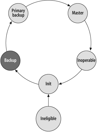
The NSRP state engine consists of six defined states of operation:
Ineligible
Inoperable
Init
Backup
Primary backup (PB)
Master
Figure 18-1 depicts the NSRP state machine.
Each VSD-Group on a device can be in any one of these states at any time. The first state, ineligible, is a user-defined state. An administrator can set a device to be ineligible to prevent it from becoming the master. This is often done when a device is suspected of having problems or needs to have maintenance performed on it. The next state, inoperable, means that an event has occurred that has rendered the device unable to become the master of a VSD-Group. A number of factors can cause this condition, such as an interface failure, track-ip failure, and others. Once the error condition that caused the device to become inoperable has cleared, or the ineligible setting is removed, the device transitions to the init state. In the init state, the device is ready to become active, but stays in a user-configurable hold-down for a period of time. This state helps to prevent state transitions in cases where the network is unstable, such as a flapping link. After the init hold timer expires, and assuming no failures transition the state back to inoperable, the device transfers itself to the primary backup state, which means that the device is ready to become the master of the group. Although a backup state is defined, it is currently unused. This state would be used if there were more than two members in a cluster (it is included here for completeness). As NSRP treats the first active device on the network as the master, if there is an existing master on the network, a device in primary backup state will not transition to master unless the existing master transitions to another state, or it preempts the mastership of the VSD-Group. To do this, the device must have a better priority than the existing master (indicated by a numerically lower value), and must be configured to preempt. Preemption is not the default setting, and you should use it with care. It is commonly used in active-active topologies, and in situations where the network administrators wish to have a particular device always be the master if it is capable. When using preempt, a hold timer indicates the number of seconds before the device can become the master of the VSD-Group. As there may be a significant amount of RTO information to synchronize in a busy network, it is typically a good idea to allow for enough time to synchronize these RTOs in the preempt hold-down timer.
NSRP is an extremely robust protocol built to handle virtually all failover scenarios seamlessly. As such, architecting NSRP can be fairly complex. For more information, see the documentation on Juniper’s web site, at http://www.juniper.net.
See Also
RFC 3768
18.1. Configure an Active-Passive NSRP Cluster in Route Mode
Solution
Set up an active-passive NSRP cluster. First, choose ports for the NSRP control and data messages:
FIREWALL-A->set interface ethernet0/7 zone haFIREWALL-A->set interface ethernet0/8 zone haFIREWALL-B->set interface ethernet0/7 zone haFIREWALL-B->set interface ethernet0/8 zone ha
Once the links are connected, enable NSRP by setting the cluster ID, VSD-Group information, and optional cluster name, and synchronize the configurations:
FIREWALL-A->set nsrp cluster id 1FIREWALL-A(M)->set nsrp cluster name FWCLUSTERFWCLUSTER:FIREWALL-A(M)->set nsrp vsd-group id 0 priority 10FIREWALL-B->set nsrp cluster id 1FIREWALL-B(B)->set nsrp cluster name FWCLUSTERFWCLUSTER:FIREWALL-B(B)->saveFWCLUSTER:FIREWALL-B(B)->exec nsrp sync global-config savedFWCLUSTER:FIREWALL-B(B)->reset
Once FIREWALL-B comes back online, finish the configuration by enabling RTO synchronization, configuring timers, setting up monitoring parameters, and configuring manage-ips:
FWCLUSTER:FIREWALL-A(M)->set nsrp rto-mirror syncFWCLUSTER:FIREWALL-A(B)->set nsrp rto-mirror session ageout-ackFWCLUSTER:FIREWALL-A(M)->set nsrp vsd-group hb-interval 200FWCLUSTER:FIREWALL-A(M)->set nsrp secondary-path ethernet0/3FWCLUSTER:FIREWALL-A(M)->set nsrp auth password iamapasswordFWCLUSTER:FIREWALL-A(M)->set nsrp encrypt password iamapasswordFWCLUSTER:FIREWALL-A(M)->set nsrp monitor interface ethernet0/1FWCLUSTER:FIREWALL-A(M)->set nsrp monitor interface ethernet0/3FWCLUSTER:FIREWALL-B(M)->set nsrp secondary-path ethernet0/3FWCLUSTER:FIREWALL-B(M)->set nsrp auth password iamapasswordFWCLUSTER:FIREWALL-B(M)->set nsrp encrypt password iamapasswordFWCLUSTER:FIREWALL-B(M)->set nsrp monitor interface ethernet0/1FWCLUSTER:FIREWALL-B(M)->set nsrp monitor interface ethernet0/3FWCLUSTER:FIREWALL-A(M)->set int e0/1 manage-ip 1.1.1.200FWCLUSTER:FIREWALL-A(M)->set int e0/3 manage-ip 2.1.1.200FWCLUSTER:FIREWALL-B(M)->set int e0/1 manage-ip 1.1.1.201FWCLUSTER:FIREWALL-B(M)->set int e0/3 manage-ip 2.1.1.201
Discussion
The simplest topology for an HA pair of firewalls is an active-passive cluster. This is shown in Figure 18-2.

Figure 18-2 depicts a sample active-passive topology. Typically, when deploying an HA firewall pair, the rest of the network is also deployed redundantly; however, this is not required. Physically, an active-passive design looks the same as an active-active design. Two firewalls are deployed at the same point in the network. In Figure 18-2, all traffic uses FIREWALL-A for transit, thus making the topology active-passive. The routers in the diagram point static routes to the VSI on each side of the firewall for routing. Because FIREWALL-A is the master, all traffic is forwarded to it by the switches which have forwarding entries for the VSI’s MAC address located on the interfaces to which FIREWALL-A is connected. Because the default failover signaling mechanism for NSRP is to use gratuitous ARP messages, switches are required for each connection to the firewall. You should not use hubs in an NSRP topology, as they will result in packets being incorrectly delivered to the passive unit.
In active-passive, one firewall acts as the master and handles all packet-processing for the network. The active-passive topology has many advantages. First, this is the simplest way to introduce HA into the network. From a network perspective, there is really no difference between an active-passive HA deployment and a single device deployment. This simplifies integration, design, and administration of the firewalls from a network perspective. It is always a good practice to avoid asymmetric traffic patterns when deploying firewalls, as state synchronization for asymmetric traffic is a challenging task at best. It is easiest to do this by deploying in an active-passive topology. Because an active-passive topology provides a single network path, outside of a configuration error or bug, there is no chance for an asymmetric traffic pattern to arise. There are three primary benefits to avoiding asymmetry. The first is that by ensuring a symmetric path, you are ensuring that the active firewall sees all packets, and state can be guaranteed to exist on the device (barring bugs, of course). The second benefit is that in ScreenOS, when an asymmetric path exists, HA data forwarding is performed. HA data forwarding uses the second HA link to forward packets to the master of the session. This link is meant as more of a safety net than a design tool, and when it is used heavily, it can result in decreased performance, especially on the NS5000 Series. The third benefit of ensuring a symmetric path is ease of troubleshooting. If a session is having trouble getting established, debugging and troubleshooting are much easier when they occur on a single device.
Configuration of the active-passive pair is a fairly simple task. It is recommended that you do this when initially installing the devices so that configuration synchronization is always in place. Unless the device comes with dedicated preassigned HA interfaces, as in the case of the NS500 and NS5000, interfaces should be assigned to the HA zone. You do this in the same way you assign interfaces to any other zone. Once the links have been assigned and are connected, set up the cluster ID. When two devices are configured with the same cluster ID, and their HA links are connected, they will form a peer relationship with each other. The cluster ID is also used as a portion of the virtual MAC address used for failover. The VSD-Group and interface ID are the other parameters which contribute to the virtual MAC definition. As the default VSD-Group ID (VSD-Group 0) is often used in NSRP clusters, and similar devices are often connected using the same interfaces, you should be careful when assigning the cluster ID. If multiple NSRP clusters share a single LAN, you should use a different cluster ID for each cluster to prevent the creation of duplicate virtual MAC addresses. When a duplicate virtual MAC address appears on a LAN, connectivity will almost certainly be disrupted. Once the two devices are configured with the same cluster ID and their HA interfaces are connected, they will begin to synchronize configurations. Note that synchronization occurs from master to backup, as well as from backup to master, so if either device’s configuration is modified, that change will be reflected on the other device. Likewise, a save command issued on either the master or the backup unit will execute a save to the peer device.
Next, set the cluster name (which is not mandatory in a pure firewall configuration, but is often useful for identifying the purpose of the cluster). After the cluster name is configured, FIREWALL-A is configured to have a priority of 10 on VSD-Group 0. In NSRP, the numerically lower priority is the “better” priority. This step ensures that FIREWALL-A will be the master if both devices come up at the same time. In a default NSRP configuration, the first active firewall on the network will become the master. It is rare that organizations desire this lack of determinism, so during an install, frequently one device is designated as the master. By setting the preempt keyword on the VSD-Group with the command set nsrp vsd-group id 0 preempt, you ensure that the device with the lower-priority value will take over mastership when it becomes active and eligible. Because this setting can cause further disruption to the network, however brief, we do not include it in this recipe. Setting lower-priority values helps to identify FIREWALL-A as the desired master. Next, the configuration is synchronized from FIREWALL-A to FIREWALL-B, and FIREWALL-B is rebooted. When you enter the command exec nsrp sync global-config save, the device, in this case FIREWALL-B, requests the configuration from FIREWALL-A and saves this configuration to flash so that upon reboot, the configurations will be synchronized. Once FIREWALL-B completes its reboot cycle it will be ready to participate in NSRP. Because FIREWALL-A is already active on the LAN, it is the master, as you can see from the command prompt which provides indication of the status of the device:
FWCLUSTER:FIREWALL-A(M)->
At this point, NSRP is functional from the point of network failover. Enable state synchronization with the command set nsrp rto-mirror-sync. Then, configure the backup device to verify that a session is expired before deleting it. The default behavior of NSRP is for the backup to install a session with a timeout of eight times that of the master’s session. When the session timer expires, it is deleted from the backup. Although this is OK for most sessions, long-lived sessions such as Border Gateway Protocol (BGP) sessions could inadvertently get deleted on the backup device. The set nsrp rto-mirror session ageout-ack command tells the backup to check the status of a session with the master before deleting it. The remaining commands in the recipe are for tuning and monitoring. By default, NSRP uses a heartbeat interval of one second and a failover threshold of three missed heartbeats, resulting in a three-second failover time for missed heartbeats. For many administrators, this is too slow. To adjust this timer, set the heartbeat interval using the set nsrp vsd-group hb-interval 200 command. This command sets the heartbeat interval to 200 milliseconds, which leads to a failover time of 600 milliseconds, which is the minimum for a failover based on heartbeat loss.
Setting the secondary path allows for a third interface to be used to elect a VSD-Group master, if for some reason both dedicated HA links were to fail. The secondary path is different from the standard HA interfaces in that only Hello packets are sent on the secondary path to elect a master; it is meant to prevent split brain and nothing more (split brain occurs when both devices attempt to become the master). Because the secondary path uses a forwarding interface, it is strongly recommended that message authentication and encryption be performed, as messages will travel over a shared interface. As you would expect, you must perform auth and encrypt settings on each device.
Next, enable monitoring of the physical interfaces, so that if there is a link loss, the device will failover. By default, interface monitoring objects have a weight of 255, and the device failover threshold is 255. This means that a failure of a single interface will cause the entire device to failover.
The final step in a basic NSRP configuration is configuration of the manage-ip. You use the manage-ip on all interfaces on each device in an NSRP cluster. Each device uses this IP address to individually communicate with the network. Without the manage-ip, administrators would not be able to manage the backup devices in an NSRP cluster.
Although configuration of active-passive NSRP is not complex, you should be careful to ensure that the appropriate design is in place. For example, switches (or one switch carved into virtual local area networks [VLANs]) should be considered a requirement, and cluster IDs must be chosen with care.
18.2. View and Troubleshoot NSRP State
Solution
	FWCLUSTER:FIREWALL-A(M)-> get nsrp
	nsrp version: 2.0

	cluster info:
	cluster id: 1, name: FWCLUSTER
	local unit id: 15372992
	active units discovered:
	index: 0, unit id: 15372992, ctrl mac: 0014f6ea92c8
	index: 1, unit id: 15128512, ctrl mac: 0014f6e6d7c8, data mac: ffffffffffff
	total number of units: 2

	VSD group info:
	init hold time: 5
	heartbeat lost threshold: 3
	heartbeat interval: 200(ms)
	master always exist: enabled
	group priority preempt holddown inelig   master       PB other members
	    0       10 no             3 no       myself 15128512
	total number of vsd groups: 1
	Total iteration=917926,time=2296775292,max=19811,min=417,average=2502

	RTO mirror info:
	run time object sync:   enabled
	route synchronization: enabled
	ping session sync: enabled
	coldstart sync done
	nsrp data packet forwarding is enabled

	nsrp link info:
	control   channel: ethernet0/4 (ifnum: 8)  mac: 0014f6ea92c8 state: up
	ha data link not available
	secondary path channel: bgroup0 (ifnum: 9)  mac: 0014f6ea92c9 state: up

	NSRP encryption password: iamapassword
	NSRP authentication password: iamapassword
	device based nsrp monitoring threshold: 255, weighted sum: 0,
	    not failed
	device based nsrp monitor interface: ethernet0/4(weight 255, UP)
	device based nsrp monitor zone:
	device based nsrp track ip: (weight: 255, enabled, not failed)
	number of gratuitous arps: 4 (default)
	config sync: enabled

	track ip: enabled
Discussion
The get nsrp command provides a comprehensive view into NSRP’s operational state on the device. The first bit of information from the output is the version number, which is always set to 2 (NSRP v1 was never called NSRP, and there is no v3 at the time of this writing). Next, we have the cluster information, which provides highlevel information about the cluster itself. The get nsrp command is actually a concatenation of six more specific commands, as you can see from the following output:
FWCLUSTER:FIREWALL-A(M)->get nsrp ?> redirect output | match output <return> cluster cluster units info counter nsrp counters group nsrp group info ha-link nsrp ha link info monitor nsrp monitored object info rto-mirror RTO mirror group info track-ip show track ip info vsd-group vsd group info FWCLUSTER:FIREWALL-A(M)-> get nsrp cluster cluster id: 1, name: FWCLUSTERlocal unit id: 15372992 active units discovered: index: 0, unit id: 15372992,ctrl mac: 0014f6ea92c8 index: 1,unit id: 15128512,ctrl mac: 0014f6e6d7c8, data mac: ffffffffffff total number of units: 2
From this output, you can see that the get nsrp cluster command provides the same output as the first stanza from the get nsrp output. From this stanza, you can see the cluster ID and name, as well as the IDs of the local and any other active units discovered in the cluster. NSRP was originally designed to support more than two members per cluster; however, this capability has not been exercised to date. For this reason, the total number of units displayed in a functional NSRP cluster should always be two. The unit ID is a unique device identifier. On each device, you can see the local unit ID, which can be used to ensure that the appropriate devices are connected. In this output, the local ID is also displayed as an active unit. The ctrl mac indicates the MAC address used for the HA control link. The output from this example was taken from an SSG20 device with no data link set. If there was an HA data link, the data MAC would be indicated under index 0 with the appropriate MAC address of the interface. To verify that the second unit ID is the appropriate device, look on the peer device:
	FWCLUSTER:FIREWALL-B(B)-> get nsrp | include local
	local unit id: 15128512
From the preceding output, you can see that it is indeed the appropriate device. The next stanza of information comes from the get nsrp vsd-group command:
	FWCLUSTER:FIREWALL-A(M)-> get nsrp vsd-group

	VSD group info:
	init hold time: 5
	heartbeat lost threshold: 3
	heartbeat interval: 200(ms)
	master always exist: enabled
	group priority preempt holddown inelig   master       PB other members
	    0       10 no             3 no       myself 15128512
	total number of vsd groups: 1
	Total iteration=832696,time=2083723367,max=16065,min=417,average=2502

	vsd group id: 0, member count: 2, master: 15372992
	member information:
	--------------------------------------------------------------------
	group  unit_id  state          prio flag rto_peer   hb miss holddown
	--------------------------------------------------------------------
	    0 15128512  primary backup  100    0        0    0    0        0
	    0 15372992  master           10    0        0    0    0        0
From this command, you can see the group information, which in our case is just vsd-group id 0. The init hold time indicates the time in seconds required before a group can become active on a device. Before the init hold time expires, the device is said to be in the init state, which is the time a device waits before attempting to participate in the NSRP process. The default of five seconds is shown here. The heartbeat lost threshold and heartbeat interval parameters represent the number of lost heartbeats and the time between heartbeats, respectively, before a device is declared down. Here, the minimum intervals of three missed heartbeats and 200 milliseconds are configured in this cluster. The master-always-exist parameter is shown next. master-always-exist is a setting that is used to allow devices to continue to forward traffic if both devices in a pair would normally be considered inoperable, as shown in Figure 18-3.
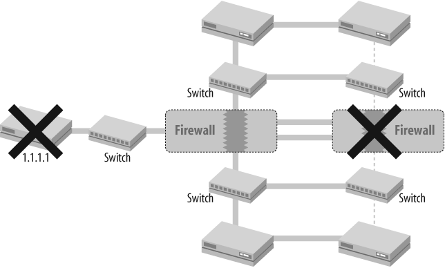
In Figure 18-3, the network has a DMZ behind a router with an IP address of 1.1.1.1. This DMZ should always be available, but the redundancy deployed in the Trusted and Untrusted networks is not carried through to the DMZ. To ensure availability, the network administrators define a track-ip object on each firewall to ensure that 1.1.1.1 is pingable. If 1.1.1.1 is not reachable from the primary device, it should failover to the secondary device. However, if the 1.1.1.1 router fails, both firewalls will go into an inoperable state, as their track-ip object will fail. This will disrupt traffic for the whole network, instead of just the DMZ. To get around this, use the set nsrp vsd-group master-always-exist command. This command tells the firewalls that if both devices become inoperable, one should still remain active on the network, preventing the blackholing of traffic.
The next section of the VSD-Group output shows information about all of the VSD-Groups on the device. Because this is an active-passive topology, only VSD-Group 0 is shown. The priority indicates the local device’s priority for the group, which in the case of FIREWALL-A is 10. Remember that the lower priority numerically is the better priority. You can also determine that preempt is disabled (the hold-down timer for preempt would be three seconds if enabled), the local device is not inoperable, the local device is the master, the primary backup is FIREWALL-B, and there are no other members in the cluster.
The output after this is specific to the get nsrp vsd-group command, and is useful in providing more detail about both devices’ status. As you can see, the priorities of both devices are shown from a single viewpoint, along with counters for events leading to state transition.
The next stanza of information in the get nsrp command is inherited from the get nsrp rto-mirror command:
	FWCLUSTER:FIREWALL-A(M)-> get nsrp rto-mirror

	RTO mirror info:
	run time object sync:   enabled
	route synchronization: enabled
	ping session sync: enabled
	coldstart sync done
From this output, notice the synchronizing RTOs, which again means that state is being shared in the cluster. Route synchronization was added in ScreenOS 6.0, and it allows the user to synchronize dynamically learned routes in an NSRP cluster to the passive member. This capability prevents the requirement of a newly promoted master to have to construct its routing table from scratch, and can reduce network reconvergence time. Ping session sync is enabled in this case, which means that session synchronization will occur for ping packets. This is the default setting, but it is frequently disabled. The coldstart sync is executed upon boot-up. A device that reboots will attempt to synchronize all RTOs from the NSRP peer.
The next bundle of information concerns the link information for HA. As we already know, NSRP typically is run on dedicated interfaces. This output is taken from an SSG20 which doesn’t support the HA zone, but in this case, ethernet0/4 is used as a dedicated link for HA:
	FWCLUSTER:FIREWALL-A(M)-> get nsrp ha-link
	total_ha_port = 0
	probe on ha-link is disabled
	secondary path channel: bgroup0 (ifnum: 9) mac: 0014f6ea92c9 state: up
	control   channel: ethernet0/4 (ifnum: 8) mac: 0014f6ea92c8 state: up
	ha data link not available
Because the SSG20 doesn’t support the HA zone, the total ports are zero. In other platforms, this value will be set to two in most cases. The HA link probe is a function used for determining the health of an HA link. By default, the physical state of the HA link is used to determine whether heartbeats should be sent and expected on the link. When the physical state of the first HA link goes down, NSRP control messages will begin to exchange on the second HA link (assuming one exists). This assumes that the firewalls are connected back to back, which is not always the case. If there is an intermediate switching layer, sometimes the physical links can remain up, but heartbeats cannot be received. In this scenario, by default, both devices will attempt to become the master (split brain), and connectivity problems will likely result. To address this, the HA link probe adds a logical connectivity test to the HA links so that if such a failure occurs, heartbeat messages first failover to the second HA link and, if configured, the HA secondary path. The secondary path itself is a forwarding interface which is the failsafe in cases where all HA links are down. The secondary path is not used for synchronization of RTOs, however, and is invoked only after multiple failovers. When invoked, a master is elected, and no RTOs are synchronized until an HA link is restored. In an active-passive environment, an HA data link is not required as there should never be any asymmetric traffic. Nevertheless, it is not a bad idea to have such a link so that you can continue to synchronize sessions in case your primary HA link goes down.
Finally, the get nsrp command displays the encryption and authentication settings:
	FWCLUSTER:FIREWALL-A(M)-> get nsrp | include (encryption|auth)
	NSRP encryption password: iamapassword
	NSRP authentication password: iamapassword
The get nsrp command also displays the number of gratuitous ARPs used to signal the network, and whether configuration synchronization is enabled:
	FWCLUSTER:FIREWALL-A(M)-> get nsrp | include (arp|config)
	number of gratuitous arps: 4 (default)
	config sync: enabled
The final bits of the get nsrp display show monitoring information from the get nsrp monitor command:
	FWCLUSTER:FIREWALL-A(M)-> get nsrp monitor
	device based nsrp monitoring threshold: 255, weighted sum: 0, not
	    failed
	device based nsrp monitor interface: ethernet0/4(weight 255, UP)
	device based nsrp monitor zone:
	device based nsrp track ip: (weight: 255, enabled, not failed)
From this output, you can see that the device has the default monitoring threshold of 255 set, and that the weighted sum of all failed objects is 0, and thus, the device has not failed over. Also note that interface ethernet 0/4 is being monitored with a weight of 255, and it is up. Because the weight of this object is equal to the failover threshold, if the interface goes down, the device will transition to the inoperable state, as you can see with the following output:
FWCLUSTER:FIREWALL-A(M)->set interface ethernet0/4 phy link-downFWCLUSTER:FIREWALL-A(I)->get nsrp vsd-groupVSD group info: init hold time: 5 heartbeat lost threshold: 3 heartbeat interval: 200(ms) master always exist: enabled group priority preempt holddown inelig master PB other members 0 10 no 3 no 15128512 none myself (inoperable) total number of vsd groups: 1 Total iteration=922386,time=2307632447,max=19811,min=417,average=2501 vsd group id: 0, member count: 2, master: 15128512 member information: -------------------------------------------------------------------- group unit_id state prio flag rto_peer hb miss holddown -------------------------------------------------------------------- 0 15128512 master 100 0 0 0 1 0 0 15372992 inoperable 10 0 0 0 0 0 FWCLUSTER:FIREWALL-A(I)->get nsrp monitordevice based nsrp monitoring threshold: 255, weighted sum: 255,failed device based nsrp monitor interface: ethernet0/4(weight 255, DOWN) device based nsrp monitor zone: device based nsrp track ip: (weight: 255, enabled, not failed) FWCLUSTER:FIREWALL-A(I)->
The NSRP zone monitoring is also displayed, along with the track-ip information. To get the specifics of the track-ip objects, use the get nsrp track-ip command:
	FWCLUSTER:FIREWALL-A(B)-> get nsrp track-ip
	ip address      interval threshold wei  interface  meth fail-count
	    success-rate
	192.168.5.1            1         3   1  auto        ping       0 100%
	failure weight: 255, threshold: 255, not failed: 0 ip(s) failed,
	    weighted sum =0
This command shows that a single IP is being tracked, 192.168.5.1, and that every second a ping is sent, and if three pings are lost, the object will be failed. Unlike interfaces, track-ip objects are set to a weight of 1 by default so that the failure of a single track-ip object will not cause a device/VSD-Group failover. You must increase the failover threshold to 255 for a single track-ip object failure to cause a device/VSD failover. Alternatively, as you can see in the get nsrp track-ip output, there is a threshold for track-ip as a whole to failover. If this is set to a value of one, failure of a single track-ip object with the default weight will cause the track-ip failure weight (255 by default, as you can see in the output of get nsrp track-ip) to be added to the device monitor’s weighted sum, and will cause the device to become inoperable.
The get nsrp command provides a comprehensive analysis of the operation of an NSRP cluster, and it is often the only command necessary to troubleshoot an NSRP problem. When you require more specific information, add the described arguments to the command to get more information.
See Also
The Introduction to this chapter; Recipe 18.3
18.3. Influence the NSRP Master
Problem
You need to configure FIREWALL-A in your cluster to always be the master if it can reach the DMZ router’s VRRP address and its Trust and Untrust interfaces are functional. Furthermore, a failure on one piece of the network should not cause the entire network to become unusable.
Solution
Use priority and preempt to set FIREWALL-A as the master:
FWCLUSTER:FIREWALL-A(B)->set nsrp vsd-group id 0 priority 10FWCLUSTER:FIREWALL-A(B)->set nsrp vsd-group id 0 preempt hold-down 90FWCLUSTER:FIREWALL-A(B)->set nsrp vsd-group id 0 preempt
Next, configure monitoring on both devices:
FWCLUSTER:FIREWALL-A(M)->set nsrp monitor interface eth0/0FWCLUSTER:FIREWALL-A(M)->set nsrp monitor interface bgroup0FWCLUSTER:FIREWALL-A(M)->set nsrp monitor interface eth0/3FWCLUSTER:FIREWALL-A(M)->set nsrp monitor track-ip ipFWCLUSTER:FIREWALL-A(M)->set nsrp monitor track-ip ip 1.1.1.1 weight 255FWCLUSTER:FIREWALL-A(M)->set nsrp monitor track-ip ip 1.1.1.1 method arpFWCLUSTER:FIREWALL-B(M)->set nsrp monitor interface eth0/0FWCLUSTER:FIREWALL-B(M)->set nsrp monitor interface bgroup0FWCLUSTER:FIREWALL-B(M)->set nsrp monitor interface eth0/3FWCLUSTER:FIREWALL-B(M)->set nsrp monitor track-ip ipFWCLUSTER:FIREWALL-B(M)->set nsrp monitor track-ip ip 1.1.1.1 weight 255FWCLUSTER:FIREWALL-B(I)->set nsrp monitor track-ip ip 1.1.1.1 method arp
Finally, enable master-always-exist, so that a failure to reach the VRRP address by both devices won’t cause a complete network failure:
FWCLUSTER:FIREWALL-A(M)-> set nsrp vsd-group master-always-existDiscussion
Many network administrators prefer to have a specific device act as the master if at all possible. It becomes their default master device, and as long as no failure conditions have caused it to enter and remain in the inoperable state, it should become the master. The use of priority and preempt enables this functionality. To ensure that all RTOs have been received, the preempt hold-down timer is set to 90 seconds on FIREWALL-A. This serves to ensure that the network is stable (from FIREWALL-A’s perspective) for at least 90 seconds before FIREWALL-A assumes mastership of VSD-Group 0. Additionally, it allows for a decent time interval to ensure successful synchronization of all RTOs before it reasserts itself as the master. If all RTOs have not been received before a preempt occurs, any session matching these RTOs will be dropped; therefore, it is a good practice to allow a decent amount of time for this to occur. The priority and preempt settings are device local settings, and thus are not propagated to FIREWALL-B. This is, of course, the desired behavior to ensure that FIREWALL-A is the master. FIREWALL-B maintains its default priority of 100.
	FWCLUSTER:FIREWALL-B(B)-> get nsrp vsd-group

	VSD group info:
	init hold time: 5
	heartbeat lost threshold: 3
	heartbeat interval: 200(ms)
	master always exist: enabled
	group priority preempt holddown inelig   master      PB other members
	    0      100 no             3 no     15372992   myself none
	total number of vsd groups: 1
	Total iteration=853767,time=2128083592,max=16696,min=418,average=2492

	vsd group id: 0, member count: 2, master: 15372992
	member information:
	--------------------------------------------------------------------
	group  unit_id  state          prio flag rto_peer   hb miss holddown
	--------------------------------------------------------------------
	    0 15372992  master           10    2        0    1    0       30
	    0 15128512  primary backup   100   0        0    0    0        0
On the other hand, you must configure monitoring parameters on both devices to be effective. Like the priority and preempt values (as well as many other NSRP configuration settings), monitoring parameters are considered device local in scope; that is, they are not synchronized as part of the configuration synchronization process. For this example, all interfaces are monitored, and the VRRP address of the DMZ router is monitored. Because the routers in the DMZ are running VRRP, ARP is chosen as the monitoring method, and the weight of the object is adjusted to 255 to ensure that if the VRRP address doesn’t respond, the device will transition to the inoperable state.
The final piece of the puzzle is to configure the master-always-exist setting. This ensures that if both devices become inoperable due to a monitored object failure, the network is not brought down. In this example, if FIREWALL-A loses connectivity to the 1.1.1.1 track-ip object, it will become inoperable, and FIREWALL-B will become the master. If, however, the failure is common to both FIREWALL-A and FIREWALL-B, FIREWALL-A will remain the master, and traffic will continue to flow between the Trust and Untrust zones.
See Also
18.4. Configure NSRP Monitors
Solution
Configure NSRP monitoring to verify interface and gateway availability:
FWCLUSTER:FIREWALL-A(M)->set nsrp monitor interface e0/1FWCLUSTER:FIREWALL-A(M)->set nsrp monitor interface e0/3FWCLUSTER:FIREWALL-A(I)->set int e0/1 manage-ip 1.1.1.200FWCLUSTER:FIREWALL-A(I)->set int e0/3 manage-ip 2.1.1.200FWCLUSTER:FIREWALL-A(M)->set nsrp monitor track-ipFWCLUSTER:FIREWALL-A(M)->set nsrp monitor track-ip ip 1.1.1.3 weight 255FWCLUSTER:FIREWALL-A(M)->set nsrp monitor track-ip ip 2.1.1.3 weight 255FWCLUSTER:FIREWALL-B(M)->set nsrp monitor interface e0/1FWCLUSTER:FIREWALL-B(M)->set nsrp monitor interface e0/3FWCLUSTER:FIREWALL-B(B)->set int e0/1 manage-ip 1.1.1.201FWCLUSTER:FIREWALL-B(M)->set int e0/3 manage-ip 2.1.1.201FWCLUSTER:FIREWALL-B(M)->set nsrp monitor track-ipFWCLUSTER:FIREWALL-B(M)->set nsrp monitor track-ip ip 1.1.1.3 weight 255FWCLUSTER:FIREWALL-B(M)->set nsrp monitor track-ip ip 2.1.1.3 weight 255
Discussion
You use NSRP monitoring to validate the integrity of a path. Interface monitoring, as described in the introduction to this chapter, is used to validate the physical state of a link. By default, interface monitoring uses a default weight of 255. You can verify this using the get nsrp monitor command:
	FWCLUSTER:FIREWALL-A(B)-> get nsrp monitor
	device based nsrp monitoring threshold: 255, weighted sum: 0, not
	    failed
	device based nsrp monitor interface: ethernet0/1(weight 255, UP)
	    ethernet0/3(weight 255, UP)
	device based nsrp monitor zone:
	device based nsrp track ip: (weight: 255, enabled, not failed)
You use the monitoring weight in NSRP to increment the weighted sum for NSRP monitoring. You can do this on a per-device basis or on a per-VSD basis. When used in a per-VSD capacity, you can use NSRP to failover a single VSD-Group so that the entire cluster is not subject to failover. This can be particularly valuable in a VSYS context. You can configure per-VSYS failover by including all interfaces in each VSYS in a unique VSD-Group. To configure per-VSD failover, use the set nsrp vsd-group id <x> monitor set of commands. In our configuration, as you can see from the output of get nsrp monitor, a single interface will cause the entire device to failover as the weight of the interface, 255, is equal to the device-based NSRP monitoring threshold.
track-ip operates slightly differently by default, as by itself it is considered an NSRP monitor object, with a weight of 255. Before track-ip is considered failed, the weighted sum of objects within the track-ip configuration must exceed the failure threshold for track-ip itself, which is set to 255 by default:
	FWCLUSTER:FIREWALL-A(B)-> get nsrp monitor track-ip
	ip address interval threshold wei interface  meth fail-count success-rate
	1.1.1.3           1         3 255 auto        ping          0 82%
	2.1.1.3           1         3 255 auto        ping          0 83%
	failure weight: 255, threshold: 255, not failed: 0 ip(s) failed,
	weighted sum = 0
Note here that the threshold for failure of track-ip is 255, and when this threshold is met or exceeded, it will add 255 to the NSRP device weighted sum. By default, the weight of each track-ip object is one, so failure of a single IP will not cause track-ip to be considered failed. To modify this behavior, include the weight of 255 in the track-ip object configuration.
track-ip uses ping as the default mechanism for failure tracking, but sometimes this is not desirable. Some VRRP implementations, for example, do not allow packets to be processed by the VIP. To handle these situations, you can configure track-ip with a method of ARP. track-ip also requires the use of a manage-ip on the device. The ping requests are sent with the manage-ip as the source address. This is required as each device maintains its own monitoring configuration and performs monitoring independently. Without a manage-ip, the backup device will have no valid source interface from which to initiate the tracking functionality. Furthermore, if track-ip packets are sourced from a VSI, and if the device becomes inoperable, they will never be able to be reinitiated, thus leaving the device in an inoperable state.
NSRP monitoring allows you to perform numerous health checks to ensure that the network is operating as expected. You should use it in virtually all NSRP configurations to ensure the fastest failover time if there is a problem on the network.
See Also
The Introduction to this chapter; Recipe 18.1; Recipe 18.2
18.5. Configure NSRP in Transparent Mode
Solution
Configure FIREWALL-A in transparent mode:
FIREWALL-A->set interface ethernet0/1 zone v1-untrustFIREWALL-A->set interface ethernet0/3 zone v1-trustFIREWALL-A->set interface vlan1 ip 1.1.1.1/24
Configure NSRP on the devices as though they were in route mode:
FIREWALL-A->set interface ethernet0/7 zone haFIREWALL-A->set interface ethernet0/8 zone haFIREWALL-B->set interface ethernet0/7 zone haFIREWALL-B->set interface ethernet0/8 zone haFIREWALL-A->set nsrp cluster id 1FIREWALL-A(M)->set nsrp cluster name FWCLUSTERFWCLUSTER:FIREWALL-A(M)->set nsrp vsd-group id 0 priority 10FIREWALL-B->set nsrp cluster id 1FIREWALL-B(B)->set nsrp cluster name FWCLUSTERFWCLUSTER:FIREWALL-B(B)->saveFWCLUSTER:FIREWALL-B(B)->exec nsrp sync global-config savedFWCLUSTER:FIREWALL-B(B)->reset
Once FIREWALL-B comes back online, finish the configuration by enabling RTO synchronization, configuring timers, setting up monitoring parameters, and configuring manage-ips:
FWCLUSTER:FIREWALL-A(M)->set nsrp rto-mirror syncFWCLUSTER:FIREWALL-A(B)->set nsrp rto-mirror session ageout-ackFWCLUSTER:FIREWALL-A(M)->set nsrp vsd-group hb-interval 200FWCLUSTER:FIREWALL-A(M)->set interface vlan1 manage-ip 1.1.1.11FWCLUSTER:FIREWALL-A(M)->set nsrp monitor interface ethernet0/1FWCLUSTER:FIREWALL-A(M)->set nsrp monitor interface ethernet0/3FWCLUSTER:FIREWALL-A(M)->set nsrp track-ipFWCLUSTER:FIREWALL-A(M)->set nsrp track-ip ip 1.1.1.10 weight 255FWCLUSTER:FIREWALL-A(M)->set nsrp track-ip ip 1.1.1.100 weight 255FWCLUSTER:FIREWALL-A(M)->set nsrp track-ip ip 1.1.1.100 interface vlan1FWCLUSTER:FIREWALL-A(M)->set nsrp track-ip ip 1.1.1.10 interface vlan1FWCLUSTER:FIREWALL-B(M)->set nsrp monitor interface ethernet0/1FWCLUSTER:FIREWALL-B(M)->set nsrp monitor interface ethernet0/3FWCLUSTER:FIREWALL-B(M)->set interface vlan1 manage-ip 1.1.1.11FWCLUSTER:FIREWALL-B(B)->set nsrp track-ipFWCLUSTER:FIREWALL-B(B)->set nsrp track-ip ip 1.1.1.10 weight 255FWCLUSTER:FIREWALL-B(B)->set nsrp track-ip ip 1.1.1.100 weight 255FWCLUSTER:FIREWALL-B(B)->set nsrp track-ip ip 1.1.1.10 interface vlan1FWCLUSTER:FIREWALL-B(B)->set nsrp track-ip ip 1.1.1.100 interface vlan1
Discussion
NSRP does not require any specific configuration to be deployed in transparent mode, outside of the monitoring parameters. There are certain considerations, however, in creating such a topology. The first and most major difference between transparent and route/NAT mode is that (at the time of this writing) in transparent mode, you can use only a single VSD-Group, namely VSD 0. The reason is because NSRP was originally envisioned to operate only between switches in a flat Layer 2 topology. In this scenario, as depicted in Figure 18-4, the problem is evident.

In this topology, a bridge loop is formed if the firewalls are operating in an active-active mode. Of course, you could run the spanning tree to eliminate the loop, but then the topology would no longer be active-active. In active-passive mode, however, the loop is broken, as the passive device in a transparent NSRP cluster does not forward any traffic. This includes Bridge Packet Data Units (BPDUs) because the links are up by default in NSRP, meaning that interfaces connected to the backup device in an NSRP cluster will go through the LISTENING and LEARNING phases of the spanning tree, and then will transition to the FORWARDING state. Although the port is in a FORWARDING state from the spanning tree’s perspective, it will not stay there. During an NSRP transition, both devices in the cluster will flap their links briefly. When the switches are running the spanning tree, this will transition them to the LISTENING state, and they will have to go through the LISTENING and LEARNING states before getting back to the FORWARDING state. This can result in an outage whose length is governed by the spanning tree’s timers.
To provide better failover times, two options are available: you can use a rapid spanning tree, or you can disable the spanning tree. The latter option can be a terrifying prospect for some organizations, and it may be explicitly prohibited by network policy. Indeed, it does require faith in NSRP as the loop prevention protocol as opposed to the spanning tree. If the switches don’t support the rapid spanning tree and multisecond failover times are unacceptable, this may be the only option.
In transparent mode, when a destination MAC address is unknown to the firewall, the firewall will flood the packet out through all interfaces except the one from which it was received. When the reply packet comes back to the firewall, the firewall will create an entry in the MAC-Learn table, much like a switch would do when it receives a packet from an unknown MAC. In NSRP, the MAC-Learn table is not considered an RTO, so in the event of a failover, the new master will have to reflood traffic for unknown MACs. In our simple topology in Figure 18-4, you will never actually see this scenario. Note the output from FIREWALL-B's getmac-learn:
FWCLUSTER:FIREWALL-B(B)->get mac-learnlink down clear mac learn table: enable Total 1024, Used 2, Create 24, Ageout 22 Flood 4, BCast 53, ReLearn 164, NoFree 0, Error 0, Drop 0 <if> <mac> <timeout> <tag id> ethernet0/3:0005.85c8.f5d0 60 1 ethernet0/3:0005.85c8.f5d1 60 1 FWCLUSTER:FIREWALL-B(B)->clear mac-learnFWCLUSTER:FIREWALL-B(B)-> get mac-learn link down clear mac learn table: enable Total 1024, Used 2, Create 26, Ageout 24 Flood 4, BCast 53, ReLearn 164, NoFree 0, Error 0, Drop 0 <if> <mac> <timeout> <tag id> ethernet0/3:0005.85c8.f5d0 60 1 ethernet0/3:0005.85c8.f5d1 60 1
Even when you clear the MAC-Learn table on FIREWALL-B, you will retain the MAC addresses for ROUTER-A and ROUTER-B. This is a consequence of having configured track-ip. By enabling track-ip, you not only monitor the availability of your routers from a packet from a packet-forwarding perspective, but also are able to keep the critical entries in the MAC-Learn table populated. You can validate this theory by disabling track-ip:
FWCLUSTER:FIREWALL-B(B)->unset nsrp track-ipFWCLUSTER:FIREWALL-B(B)->clear mac-learnFWCLUSTER:FIREWALL-B(B)->get macmac-learn show mac learning table FWCLUSTER:FIREWALL-B(B)->get mac-learnlink down clear mac learn table: enable Total 1024, Used 0, Create 26, Ageout 26 Flood 4, BCast 53, ReLearn 164, NoFree 0, Error 0, Drop lt <if> <mac> <timeout> <tag id>
Note that the router MAC addresses are no longer retained.
In transparent mode, as in route mode, RTO synchronization enables stateful device failover. Instead of signaling network failover by issuing gratuitous ARPs, however, NSRP signals failover to the network by bouncing the links on both cluster members. This has the effect of clearing the switches’ forwarding databases. Without a forwarding database entry for a given MAC, the switches, like the firewalls, flood the packets out through all ports except those on which the packets were received, until the forwarding database is built.
As with NSRP in route mode, monitoring is recommended for all interfaces, as is track-ip. track-ip in transparent mode uses the vlan1 IP for the source of track-ip packets, or more accurately, the manage-ip of vlan1. With transparent mode, vlan1 and its manage-ip should be set up in the same subnet as the surrounding devices.
See Also
18.6. Configure an Active-Active NSRP Cluster
Problem
You need to use both devices in an NSRP pair to forward traffic.
Solution
Configure an active-active NSRP cluster:
FIREWALL-A->set nsrp cluster id 1FIREWALL-A(M)->set nsrp cluster name FWCLUSTERFWCLUSTER:FIREWALL-A(M)->set nsrp vsd-group id 0 priority 10FIREWALL-B->set nsrp cluster id 1FIREWALL-B(B)->set nsrp vsd-group id 1 priority 10FWCLUSTER:FIREWALL-B(B)->saveFWCLUSTER:FIREWALL-B(B)->exec nsrp sync global-config savedFWCLUSTER:FIREWALL-B(B)->reset
Once FIREWALL-B comes back online, continue the configuration by enabling RTO synchronization, configuring timers, and setting up monitoring parameters:
FWCLUSTER:FIREWALL-A(M)->set nsrp rto-mirror syncFWCLUSTER:FIREWALL-A(M)->set nsrp vsd-group hb-interval 200FWCLUSTER:FIREWALL-A(M)->set nsrp data-forwardingFWCLUSTER:FIREWALL-A(M)->set nsrp monitor interface ethernet0/1FWCLUSTER:FIREWALL-A(M)->set nsrp monitor interface ethernet0/3FWCLUSTER:FIREWALL-B(M)->set nsrp monitor interface ethernet0/1FWCLUSTER:FIREWALL-B(M)->set nsrp monitor interface ethernet0/3
Finally, ensure that the two devices remain active, when possible, by configuring preempt for the appropriate groups, and setting master-always-exist:
FWCLUSTER:FIREWALL-A(M)->set nsrp vsd-group id 0 preemptFWCLUSTER:FIREWALL-A(M)->set nsrp vsd-group id 0 preempt hold-down 90FWCLUSTER:FIREWALL-A(M)->set nsrp vsd-group master-always-existFWCLUSTER:FIREWALL-B(M)->set nsrp vsd-group id 1 preemptFWCLUSTER:FIREWALL-B(M)->set nsrp vsd-group id 1 preempt hold-down 90
Discussion
NSRP in active-active mode is conceptually similar to NSRP in active-passive mode. Figure 18-5 shows a typical active-active configuration.

Instead of having a single VSD-Group to forward traffic in active-active mode, NSRP uses two (or sometimes more) VSD-Groups. The effect is that each device can become the master for a subset of sessions and each device can forward traffic. To deliver traffic to the firewalls, some routes are pointed at VSI:0 and some routes are pointed at VSI:1. This creates a load-sharing environment on the firewalls. There are three main reasons for deploying an active-active topology:
To increase forwarding capacity
To ensure that the “backup” device is functional
To provide independent failover for a subset of traffic
Of these three reasons, you should be careful when deciding to deploy active-active when an increase in forwarding capacity is the motivator. Juniper’s firewall products operate at extremely high performance. Deploying an active-active NSRP cluster to increase performance may not be necessary, and may have unintended results. Although using two devices to forward traffic instead of one will increase the system’s theoretical throughput, if NSRP detects a failure and one of the devices becomes inoperable—and if the throughput at that time exceeds the capacity of a single device—data will certainly be lost and full redundancy cannot be said to have been provided.
Another unintended consequence may arise. Unless routing is configured carefully, asymmetric traffic can easily result. NSRP handles asymmetric traffic by performing NSRP data forwarding. Data forwarding in NSRP occurs when a packet arrives on a firewall and the VSD-Group the packet is destined to (derived from the destination MAC address in the packet) does not have an existing session for the packet. When such packets arrive on a device, they are immediately forwarded across the HA data link to the peer device in the cluster for processing, using the MAC address of the VSI that the original packet was destined to as the source of the forwarded packet. When this packet it received on the master looks like it was found on the local VSI, session lookup is done, and the packet is forwarded appropriately. On the NS5000, this forwarding is particularly costly, as the HA links are located on the management module, and thus the CPU is used to forward them. If there is a significant amount of this traffic on a pair of NS5000s, decreased forwarding performance will be the likely result. Even on platforms where this is not the case, debugging can get trickier in an environment with HA data forwarding. HA data forwarding is a wonderfully useful mechanism; however, it is best used in failure conditions, rather than as a design principle. To ensure symmetry, various routing tricks including NAT, policy-based routing, and filter-based forwarding are recommended. For more information on policy-based routing, see Chapter 7.
Although using an active-active pair to increase forwarding capacity is not recommended, ensuring the existence of an operational backup device is frequently desired, and is a useful reason to deploy active-active. Providing independent failover for a subset of traffic is also desired in some high-performance environments, where even the subsecond failover capabilities of NSRP are deemed too disruptive. Again, with any motivation for deploying an active-active topology, you must be careful to ensure symmetry as much as possible.
The configuration of active-active NSRP is similar to active-passive because in NSRP, when the first device on the network comes up, it becomes the master. The addition of the preempt command is required, as well as the explicit configuration of priority for each VSD-Group. In Recipe 18.1, we used only the default VSD-Group 0. To run an active-active configuration, a minimum of two VSD-Groups are used. Create a newVSD-Group with the set nsrp vsd-group id 1 priority 10 command. When executed on FIREWALL-B, the configuration is synchronized with FIREWALL-A, with a notable exception—the priority—as can be seen from FIREWALL-A’s configuration:
	FWCLUSTER:FIREWALL-A(M)-> get config | include vsd-group
	set nsrp vsd-group master-always-exist
	set nsrp vsd-group id 0 priority 10
	set nsrp vsd-group id 0 preempt
	set nsrp vsd-group id 0 preempt hold-down 90
	set nsrp vsd-group id 1 priority 100
Note that the default priority of 100 is assigned to the VSD-Group. Although the creation of a VSD-Group is a synchronized component of a configuration, as one would expect, the priority of the group is a local-only setting. As previously mentioned, preempt is recommended for a successful NSRP configuration, as it will force both devices, when capable, to assume mastership of one of the VSD-Groups. Set the holddown timer to 90 seconds to avoid excessive state changes in an unstable network, and ensure full synchronization of RTOs. (Setting the hold-down timer applies only to the preempt function.) If the peer device becomes inoperable before the hold-down timer expires, the device will still become the master as long as it is not inoperable.
On examining the get nsrp vsd-group command, you’ll see that the pair is in an active-active state:
	FWCLUSTER:FIREWALL-A(M)-> get nsrp vsd-group

	VSD group info:
	init hold time: 5
	heartbeat lost threshold: 3
	heartbeat interval: 1000(ms)
	master always exist: enabled
	group priority preempt holddown inelig   master       PB other members
	    0       10 yes           90 no       myself  4274560
	    1      100 no             3 no      4274560   myself
	total number of vsd groups: 2
	Total iteration=2713608,time=565665873,max=21663,min=86,average=208

	vsd group id: 0, member count: 2, master: 4687744
	member information:
	---------------------------------------------------------------------
	group  unit_id  state          prio flag rto_peer   hb miss holddown
	---------------------------------------------------------------------
	    0  4274560  primary backup  100    0        0    1    0        0
	    0  4687744  master           10    2        0    0    0       90

	vsd group id: 1, member count: 2, master: 4274560
	member information:
	---------------------------------------------------------------------
	group  unit_id  state          prio flag rto_peer   hb miss holddown
	---------------------------------------------------------------------
	    1  4274560  master           10    2        0    1    0       90
	    1  4687744  primary backup  100    0        0    0    0        0
As expected, each device is the master of one VSD-Group. Note in the command prompt the existence of the M designating FIREWALL-A as the master. Examine FIREWALL-B and you’ll see the same:
FWCLUSTER:FIREWALL-B(M)->
This is the expected behavior in an operational active-active configuration. If a failure occurs, one device should become master of both VSD-Groups. Switching FIREWALL-B to backup mode, you can see this:
FWCLUSTER:FIREWALL-B(M)->exec nsrp vsd-group id 1 mode backupStart deactivate session (vsd=1) ... 0 sessions deactivated FWCLUSTER:FIREWALL-A(M)->get nsrp vsd-groupVSD group info: init hold time: 5 heartbeat lost threshold: 3 heartbeat interval: 1000(ms) master always exist: enabled group priority preempt holddown inelig master PB other members 0 10 yes 90 no myself 4274560 1 100 no 3 no myself 4274560 total number of vsd groups: 2 Total iteration=2716552,time=567481260,max=21663,min=86,average=208 vsd group id: 0, member count: 2, master: 4687744 member information: ------------------------------------------------------------------- group unit_id state prio flag rto_peer hb miss holddown ------------------------------------------------------------------- 0 4274560 primary backup 100 0 0 0 0 0 0 4687744 master 10 2 0 0 0 90 vsd group id: 1, member count: 2, master: 4687744 member information: ------------------------------------------------------------------- group unit_id state prio flag rto_peer hb miss holddown ------------------------------------------------------------------- 1 4274560 primary backup 10 2 0 1 0 90 1 4687744 master 100 0 0 0 0 0
After the expiration of the hold-down timer, FIREWALL-B will preempt the mastership of VSG-Group 1, and the pair will again become active-active.
See Also
18.7. Configure NSRP with OSPF
Solution
Configure a VSD-less cluster:
FWCLUSTER:FIREWALL-A(M)->unset nsrp vsd-group id 0FWCLUSTER:FIREWALL-A(B)->set nsrp rto-mirror session non-vsiFWCLUSTER:FIREWALL-A(M)->set interface e0/1 ip 1.1.1.1/24FWCLUSTER:FIREWALL-A(M)->set interface e0/3 ip 2.1.1.1/24FWCLUSTER:FIREWALL-B(M)->set inte e0/1 ip 1.1.2.1/24FWCLUSTER:FIREWALL-B(M)->set inte e0/3 ip 2.1.2.1/24
Enable OSPF on each device:
FWCLUSTER:FIREWALL-A(M)->set vrouter trust-vrFWCLUSTER:FIREWALL-A(trust-vr)(M)->set protocol ospfFWCLUSTER:FIREWALL-A(trust-vr/ospf)(M)->set area 0FWCLUSTER:FIREWALL-A(trust-vr/ospf)(M)->set enableFWCLUSTER:FIREWALL-A(trust-vr/ospf)(M)->endFWCLUSTER:FIREWALL-A(M)->set interface ethernet0/1 protocol ospf area 0FWCLUSTER:FIREWALL-A(M)->set interface ethernet0/1 protocol ospf link-type p2pFWCLUSTER:FIREWALL-A(M)->set interface ethernet0/1 protocol ospf enableFWCLUSTER:FIREWALL-A(M)->set interface ethernet0/3 protocol ospf area 0FWCLUSTER:FIREWALL-A(M)->set interface ethernet0/3 protocol ospf link-type p2pFWCLUSTER:FIREWALL-A(M)->set interface ethernet0/3 protocol ospf enableFWCLUSTER:FIREWALL-B(M)->set interface ethernet0/1 protocol ospf area 0FWCLUSTER:FIREWALL-B(M)->set interface ethernet0/3 protocol ospf area 0FWCLUSTER:FIREWALL-B(M)->set interface ethernet0/1 protocol ospf cost 100FWCLUSTER:FIREWALL-B(M)->set interface ethernet0/3 protocol ospf cost 100FWCLUSTER:FIREWALL-B(M)->set interface ethernet0/1 protocol ospf link-type p2pFWCLUSTER:FIREWALL-B(M)->set interface ethernet0/3 protocol ospf link-type p2pFWCLUSTER:FIREWALL-B(M)->set interface ethernet0/1 protocol ospf enableFWCLUSTER:FIREWALL-B(M)->set interface ethernet0/3 protocol ospf enable
Discussion
VSD-less clusters were added in ScreenOS 5.0 with the goal of separating the failover component of NSRP from the session synchronization component. Prior to ScreenOS 5.0, when a dynamic routing protocol was run in conjunction with NSRP, failover behavior was not always predictable, and was often slow, because when using NSRP with the default VSD-Group of 0, interface IP addresses are shared among devices in the cluster. As a single IP address faces the network per VSD-Group, only one device can form routing protocol neighborships per VSD-Group at a time. In the default active-passive setup, this means that when the active device in a cluster becomes inoperable and it fails over, the new master will not yet have any routes with which to forward traffic. Furthermore, it may not even have built the sessions because there were no routes for the active sessions.
Active-active mode is no better, and maybe worse. In active-active mode, each device will have neighbors built on its respective VSIs. Upon failover, however, the master will become its own neighbor, as you can see in the following output which assumes configuration of OSPF on VSIs:
FWCLUSTER:FIREWALL-A(M)->get vrouter trust-vr protocol ospf neighborVR:trust-vr RouterId: 172.25.113.177--------------------------------- Neighbor(s) on interface ethernet0/3:1 (Area 0.0.0.0) IpAddr/IfIndex RouterId Pri State Opt Up StateChg ---------------------------------------------------------------------- 2.1.1.1 172.25.113.177 1 2Way E 00:00:10 (+3 -0) 2.1.1.3 10.3.3.2 128 Full E 00:00:12 (+7 -0) 2.1.1.4 10.30.3.2 128 Full E 00:00:12 (+7 -0) Neighbor(s) on interface ethernet0/1:1 (Area 0.0.0.0) IpAddr/IfIndex RouterId Pri State Opt Up StateChg ---------------------------------------------------------------------- 1.1.1.1 172.25.113.177 1 2Way E 00:00:10 (+3 -0) 1.1.1.3 10.2.2.2 128 Full E 00:00:12 (+7 -0) 1.1.1.4 10.20.2.2 128 Full E 00:00:12 (+7 -0) Neighbor(s) on interface ethernet0/1:1 (Area 0.0.0.0) IpAddr/IfIndex RouterId Pri State Opt Up StateChg ----------------------------------------------------------------------1.1.1.2 172.25.113.145 1 2Way E 00:00:21 (+3 -0) 1.1.1.2 172.25.113.177 1 2Way E 00:00:10 (+4 -1)1.1.1.3 10.2.2.2 128 Full E 00:11:45 (+7 -0) 1.1.1.4 10.20.2.2 128 Full E 00:11:57 (+7 -0) Neighbor(s) on interface ethernet0/1:1 (Area 0.0.0.0) IpAddr/IfIndex RouterId Pri State Opt Up StateChg ----------------------------------------------------------------------2.1.1.2 172.25.113.145 1 2Way E 00:00:41 (+3 -0) 2.1.1.2 172.25.113.177 1 2Way E 00:00:22 (+4 -1)2.1.1.3 10.3.3.2 128 Full E 00:11:57 (+7 -0) 2.1.1.4 10.30.3.2 128 Full E 00:11:57 (+7 -0)
As you can see from the output of get vrouter trust-vr protocol ospf neighbor when OSPF is configured in a traditional active-active topology, if FIREWALL-B fails, FIREWALL-A becomes its own neighbor and has multiple neighbors with the same neighbor address. This condition will continue until the dead interval expires, at which point FIREWALL-A will only be its own neighbor. When this happens, traffic flows can become unpredictable, network stability can suffer, and troubleshooting can become challenging.
There are two possible solutions to this problem: one we describe in Recipe 18.8; the other, described here, is to disable the failover component of NSRP and let the routing protocol handle failover. Figure 18-6 shows an example OSPF network.

In this network, OSPF costs are used to determine the active path, and point-to-point links are used. There are two reasons for using point-to-point links. The first is that if an intermediate switch layer connects FIREWALL-A to routers A and B, there is no way to deterministically cost the links. This will result in asymmetric routing. The second reason is to decrease failover time. To do this, point-to-point interfaces are used in many routed networks because link failure detection is typically faster than through a switched network. Furthermore, there is no need to go through the Designated Router/Backup Designated Router (DR/BDR) election process if the interface type is point-to-point. Although this recipe covers OSPF, conceptually the design parameters are the same for the Routing Information Protocol (RIP) and BGP, although the terminology will change.
To configure the firewalls for a network with the routing protocol controlling failover, first disable vsd-group id 0. When you enter the unset nsrp vsd-group id 0 command, the firewalls no longer synchronize configuration information pertaining to interfaces. This includes IP addresses, all other interface-specific configuration, and static routes. When VSD-Group 0 is unset, each firewall maintains its own IP information, and as such, each must be configured independently on each firewall. At this point in the configuration, both firewalls show a “B” for backup in their prompt, indicating they are not masters of any sessions. RTOs for non-VSI sessions must be explicitly enabled for synchronization. The command set nsrp rto-mirror session non-vsi does this. When this command is entered, both firewalls’ prompts change to “M,” indicating that they can be the master of any sessions that arrive on the device.
One thing to note with a VSD-less cluster is that there is no synchronization of embryonic sessions and no HA data-path forwarding. An embryonic session is a session that is only partially created. This would be the case in a session where a SYN had been seen, but there was no SYN-ACK yet. Because NSRP determines whether to perform data-path forwarding based on the VSD-Group of the packet, and whether a session exists in its locally active VSD-Group for such a packet, it follows that when there is no VSD-Group, data won’t be forwarded across the HA data link. This is, in fact, the behavior of NSRP. The consequence of this is that in a VSD-less cluster, asymmetric traffic is not supported at all.
Next, you configure the OSPF settings. Because asymmetry is not supported in a VSD-less topology, costs must be configured to ensure a symmetric path. Additionally, the interfaces are configured as OSPF point-to-point link types so as to avoid the overhead in electing and maintaining DR/BDR. In our sample network, all traffic will take the lowest-cost path through FIREWALL-A, unless this path becomes unavailable. In this case, once OSPF reconverges, all traffic will flow through FIREWALL-B.
VSD-less clusters represent a powerful tool for being able to deploy dynamically routed solutions with session synchronization. They provide all of the state information as a standard NSRP configuration while leaving the network failover component to a standard routing protocol. In many situations, network requirements may dictate that a dynamic protocol be run. As long as symmetry is maintained, VSD-less clusters provide an excellent way to accomplish this.
See Also
18.8. Provide Subsecond Failover with NSRP and BGP
Solution
Disable VSD-Group 0, configure interfaces, and create a new VSD-Group for failover:
FWCLUSTER:FIREWALL-A(M)->unset nsrp vsd-group id 0FWCLUSTER:FIREWALL-A(B)->set nsrp rto-mirror session non-vsiFWCLUSTER:FIREWALL-A(M)->set interface ethernet0/1 ip 1.1.1.1/24FWCLUSTER:FIREWALL-A(M)->set interface ethernet0/3 ip 2.1.1.1/24FWCLUSTER:FIREWALL-B(M)->set interface ethernet0/1 ip 1.1.1.2/24FWCLUSTER:FIREWALL-B(M)->set interface ethernet0/3 ip 2.1.1.2/24FWCLUSTER:FIREWALL-A(M)->set nsrp vsd-group id 1 priority 10FWCLUSTER:FIREWALL-A(M)->set interface ethernet0/1:1 ip 1.1.1.254/24FWCLUSTER:FIREWALL-A(M)->set interface ethernet0/3:1 ip 2.1.1.254/24FWCLUSTER:FIREWALL-A(M)->set nsrp vsd-group hb-interval 200FWCLUSTER:FIREWALL-A(M)->set nsrp monitor interface e0/1FWCLUSTER:FIREWALL-A(M)->set nsrp monitor interface e0/3FWCLUSTER:FIREWALL-B(M)->set nsrp monitor interface e0/1FWCLUSTER:FIREWALL-B(M)->set nsrp monitor interface e0/3
Configure BGP on the firewalls:
FWCLUSTER:FIREWALL-A(M)->set vrouter trust-vrFWCLUSTER:FIREWALL-A(trust-vr)(M)->set protocol bgp 65535FWCLUSTER:FIREWALL-A(trust-vr/bgp)(M)->set enableFWCLUSTER:FIREWALL-A(trust-vr/bgp)(M)->set neighbor 1.1.1.3 remote-as 65501FWCLUSTER:FIREWALL-A(trust-vr/bgp)(M)->set neighbor 1.1.1.4 remote-as 65501FWCLUSTER:FIREWALL-A(trust-vr/bgp)(M)->set neighbor 2.1.1.3 remote-as 65502FWCLUSTER:FIREWALL-A(trust-vr/bgp)(M)->set neighbor 2.1.1.4 remote-as 65502FWCLUSTER:FIREWALL-A(trust-vr/bgp)(M)->set neighbor 1.1.1.3 enableFWCLUSTER:FIREWALL-A(trust-vr/bgp)(M)->set neighbor 1.1.1.4 enableFWCLUSTER:FIREWALL-A(trust-vr/bgp)(M)->set neighbor 2.1.1.4 enableFWCLUSTER:FIREWALL-A(trust-vr/bgp)(M)->set neighbor 2.1.1.3 enableFWCLUSTER:FIREWALL-A(trust-vr/bgp)(M)->unset synchronizationFWCLUSTER:FIREWALL-A(trust-vr/bgp)(M)->endFWCLUSTER:FIREWALL-A(M)->set interface e0/1 protocol bgpFWCLUSTER:FIREWALL-A(M)->set interface e0/3 protocol bgpFWCLUSTER:FIREWALL-B(M)->set interface e0/1 protocol bgpFWCLUSTER:FIREWALL-B(M)->set interface e0/3 protocol bgp
Configure a route map so that BGP advertised routes are sent with a next-hop attribute of the VSI:
FWCLUSTER:FIREWALL-A(M)->set vrouter trust-vrFWCLUSTER:FIREWALL-A(trust-vr)(M)->set access-list 10 permit ip 0.0.0.0/0 10FWCLUSTER:FIREWALL-A(trust-vr)(M)->set route-map name set-nh-vsi- Upstream permit 10FWCLUSTER:FIREWALL-A(trust-vr/set-nh-vsi-upstream-10)(M)->set match ip 10FWCLUSTER:FIREWALL-A(trust-vr/set-nh-vsi-upstream-10)(M)->set next- hop 1.1.1.254FWCLUSTER:FIREWALL-A(trust-vr/set-nh-vsi-upstream-10)(M)->exitFWCLUSTER:FIREWALL-A(trust-vr)(M)->set protocol bgpFWCLUSTER:FIREWALL-A(trust-vr/bgp)(M)->set neighbor 1.1.1.3 route-map set-nh-vsi-upstream outFWCLUSTER:FIREWALL-A(trust-vr/bgp)(M)->set neighbor 1.1.1.4 route-map set-nh-vsi-upstream outFWCLUSTER:FIREWALL-A(trust-vr/bgp)(M)->exitFWCLUSTER:FIREWALL-A(trust-vr)(M)->set route-map name set-nh-vsi-downstream permit 10FWCLUSTER:FIREWALL-A(trust-vr/set-nh-vsi-downstream-10)(M)->set match Ip 10FWCLUSTER:FIREWALL-A(trust-vr/set-nh-vsi-downstream-10)(M)->set next- Hop 2.1.1.254FWCLUSTER:FIREWALL-A(trust-vr/set-nh-vsi-downstream-10)(M)->exitFWCLUSTER:FIREWALL-A(trust-vr)(M)->set protocol bgpFWCLUSTER:FIREWALL-A(trust-vr/bgp)(M)->set neighbor 2.1.1.3 route-map set-nh-vsi-downstream outFWCLUSTER:FIREWALL-A(trust-vr/bgp)(M)->set neighbor 2.1.1.4 route-map set-nh-vsi-downstream outFWCLUSTER:FIREWALL-A(trust-vr/bgp)(M)->endFWCLUSTER:FIREWALL-A(M)->
Finally, configure FIREWALL-B to advertise routes using an inactive interface for the next-hop:
FWCLUSTER:FIREWALL-B(M)-> set vrouter trust-vr adv-inact-interfaceDiscussion
BGP is a powerful protocol in any environment, and firewalls are no exception. In fact, the granular policy controls available in BGP make it an ideal routing protocol to run in a firewall environment. The biggest problem with running BGP in a firewall environment is that the failover timers are typically considered too slow. Although ScreenOS allows the configuration of BGP timers as low as a one-second keepalive and three-second hold timer, not all router vendors allow timers to be configured so low, and even so, if you can get subsecond failover, it’s nice to have it. We examine this in greater detail starting with Figure 18-7, which shows a sample BGP network.
In Figure 18-7’s environment, three separate ASs are used: one for the firewalls, and one each for the Trusted and Untrusted networks. This allows some control over the routes that the firewalls advertise. If there was a single AS, with the firewalls in the middle, they would not be able to control how routes were advertised from routers A and B to routers C and D because the advertisement would be direct from A to C, A to D, and so on. An IGP or static route would also be required. By using three separate ASs, the design is simplified and more control is retained.
BGP allows for granular modification of its attributes. One attribute that is frequently modified is next-hop. Usually, this is set to the value of self at EBGP boundaries so that AS-external routes do not need to be included in the IGP, but in our case, we modify the next-hop setting to reflect the VSI address. By setting the next hop to the VSI, extremely fast convergence is provided.

The first step in getting this set up is to configure a VSD-less cluster under NSRP, as in Recipe 18.6. VSD-less clusters allow for the devices in a cluster to maintain unique interface configurations. As such, you need to configure the IP addresses independently on each device. Next, configure a new VSD-Group and a VSI on the Trusted and Untrusted interfaces. The state of the interfaces for both the VSI and non-VSI configured on both devices is as expected:
	FWCLUSTER:FIREWALL-A(M)-> get int

	A - Active, I - Inactive, U - Up, D - Down, R - Ready

	Interfaces in vsys Root:
	Name      IP Address        Zone    MAC             VLAN State VSD
	eth0/0    172.25.113.177/24 MGT     0017.cb47.8780     -   U   -
	eth0/1    1.1.1.1/24        Untrust 0017.cb47.8785     -   U   -
	eth0/1:1  1.1.1.254/24      Untrust 0010.dbff.2051     -   U   1
	eth0/2    0.0.0.0/0         DMZ     0017.cb47.8786     -   U   -
	eth0/3    2.1.1.1/24        Trust   0017.cb47.8787     -   U   -
	eth0/3:1  2.1.1.254/24      Trust   0010.dbff.2071     -   U   1
	eth0/4    0.0.0.0/0         Null    0017.cb47.8788     -   D   -
	eth0/5    0.0.0.0/0         Null    0017.cb47.8789     -   D   -
	eth0/6    0.0.0.0/0         Null    0017.cb47.878a     -   D   -
	eth0/7    0.0.0.0/0         HA      0017.cb47.878b     -   U   -
	eth0/8    0.0.0.0/0         HA      0017.cb47.878c     -   U   -
	eth0/9    0.0.0.0/0         Null    0017.cb47.878d     -   D   -
	bgroup0/0 0.0.0.0/0         Null    0017.cb47.878e     -   D   -
	bgroup0/1 0.0.0.0/0         Null    0017.cb47.8795     -   D   -
	bgroup0/2 0.0.0.0/0         Null    0017.cb47.8796     -   D   -
	vlan1     0.0.0.0/0         VLAN    0017.cb47.878f     1   D   -
	null      0.0.0.0/0         Null    N/A                -   U   0
On FIREWALL-B:
	FWCLUSTER:FIREWALL-B(M)-> get int

	A - Active, I - Inactive, U - Up, D - Down, R - Ready

	Interfaces in vsys Root:
	Name      IP Address        Zone    MAC            VLAN State VSD
	eth0/0    172.25.113.145/24 MGT     0017.cb41.3980    -   U   -
	eth0/1    1.1.1.2/24        Untrust 0017.cb41.3985    -   U   -
	eth0/1:1  1.1.1.254/24      Untrust 0010.dbff.2051    -   I   1
	eth0/2    0.0.0.0/0         DMZ     0017.cb41.3986    -   U   -
	eth0/3    2.1.1.2/24        Trust   0017.cb41.3987    -   U   -
	eth0/3:1  2.1.1.254/24      Trust   0010.dbff.2071    -   I   1
	eth0/4    0.0.0.0/0         Null    0017.cb41.3988    -   D   -
	eth0/5    0.0.0.0/0         Null    0017.cb41.3989    -   D   -
	eth0/6    0.0.0.0/0         Null    0017.cb41.398a    -   D   -
	eth0/7    0.0.0.0/0         HA      0017.cb41.398b    -   U   -
	eth0/8    0.0.0.0/0         HA      0017.cb41.398c    -   U   -
	eth0/9    0.0.0.0/0         Null    0017.cb41.398d    -   D   -
	bgroup0/0 0.0.0.0/0         Null    0017.cb41.398e    -   D   -
	bgroup0/1 0.0.0.0/0         Null    0017.cb41.3995    -   D   -
	bgroup0/2 0.0.0.0/0         Null    0017.cb41.3996    -   D   -
	vlan1     0.0.0.0/0         VLAN    0017.cb41.398f    1   D   -
	null      0.0.0.0/0         Null    N/A               -   U   0
The non-VSI interfaces are indeed properly set up on each device, as are the VSIs.
Next, configure BGP as you would in a standard BGP configuration. Again, because the interface-specific information is not synchronized when VSD-Group 0 is unset, you need to specifically enable BGP on each device. Once basic BGP is set up, configure route maps that match all traffic, and set the next-hop address to be the appropriate VSI. Apply these route maps to the appropriate neighbors. At this point, the upstream and downstream routers will send traffic to the VSI addresses of the fire-wall. When you apply the command set vrouter trust-vr adv-inact-interface to FIREWALL-B, the command allows the firewall to advertise the routes using the VSI for the next hop even though the interface is inactive on the device. You can see this in the routing table on ROUTER-A:
	ROUTER-A.inet.0: 6 destinations, 10 routes (6 active, 0 holddown, 0
	    hidden)
	+ = Active Route, - = Last Active, * = Both

	1.1.1.0/24         *[Direct/0] 00:29:06
	                    > via fe-0/0/0.2
	1.1.1.3/32         *[Local/0] 00:29:06
	                      Local via fe-0/0/0.2
	10.1.1.0/24        *[Static/5] 00:15:26
	                      Reject
	10.2.1.0/24        *[BGP/170] 00:00:12, localpref 100
	                      AS path: I
	                    > to 1.1.1.4 via fe-0/0/0.2
	10.3.1.0/24        *[BGP/170] 00:07:02, localpref 100, from 1.1.1.2
	                      AS path: 65535 65502 I
	                    > to 1.1.1.254 via fe-0/0/0.2
	                    [BGP/170] 00:07:02, localpref 100, from 1.1.1.1
	                      AS path: 65535 65502 I
	                    > to 1.1.1.254 via fe-0/0/0.2
	                    [BGP/170] 00:04:24, localpref 100, from 1.1.1.4
	                      AS path: 65535 65502 I
	                    > to 1.1.1.254 via fe-0/0/0.2
	10.4.1.0/24        *[BGP/170] 00:07:02, localpref 100, from 1.1.1.2
	                      AS path: 65535 65502 I
	                    > to 1.1.1.254 via fe-0/0/0.2
	                    [BGP/170] 00:07:02, localpref 100, from 1.1.1.1
	                      AS path: 65535 65502 I
	                    > to 1.1.1.254 via fe-0/0/0.2
	                    [BGP/170] 00:04:24, localpref 100, from 1.1.1.4
	                      AS path: 65535 65502 I
	                    > to 1.1.1.254 via fe-0/0/0.2
Both FIREWALL-A and FIREWALL-B advertise the routes identically, so that if there is a failover from FIREWALL-A to FIREWALL-B, traffic will continue to flow using the VSIs as the next hops. Eventually, the BGP sessions from the routers to FIREWALL-A will expire, and all routes learned from FIREWALL-A will be withdrawn and replaced with those from FIREWALL-B. Because the routes are identical, there will be no disruption from this event, as the network does not have to reconverge.
BGP is a terrific routing protocol to run on firewalls because of its intrinsic capabilities for applying policy to routing information. The ability to integrate so well with NSRP and to provide subsecond failover is powerful, and allows you the best of both worlds: providing subsecond failover, and the ease of administration provided with dynamic routing.
See Also
18.9. Synchronize Dynamic Routes in NSRP
Solution
Configure a dynamic routing protocol and enable route synchronization:
FWCLUSTER:FIREWALL-A(M)->set vrouter trust-vrFWCLUSTER:FIREWALL-A(trust-vr)(M)->set protocol ripFWCLUSTER:FIREWALL-A(trust-vr/rip)(M)->set enableFWCLUSTER:FIREWALL-A(trust-vr/rip)(M)->endFWCLUSTER:FIREWALL-A(M)->set int e0/1 proto ripFWCLUSTER:FIREWALL-A(M)->set int e0/1 proto rip enableFWCLUSTER:FIREWALL-A(M)->set int e0/3 proto ripFWCLUSTER:FIREWALL-A(M)->set int e0/3 proto rip enableFWCLUSTER:FIREWALL-A(M)->set nsrp rto-mirror route
Discussion
The ability to synchronize routes from primary to backup devices in an NSRP cluster was added in ScreenOS 6.0. This capability removes the problems explored in Recipe 18.6 with establishing new neighbors upon failover. The solution employed is simply to synchronize the routes from the master to the backup, and the important keyword here is routes. Although routes are synchronized, the underlying entities from which the routing table is derived, such as the link state database in OSPF, are not synchronized. You can see this in the following output taken when OSPF is the protocol running on the firewalls:
	FWCLUSTER:FIREWALL-B(B)-> get route

	IPv4 Dest-Routes for <untrust-vr> (0 entries)
	---------------------------------------------------------------------
	H: Host C: Connected S: Static A: Auto-Exported
	I: Imported R: RIP P: Permanent D: Auto-Discovered
	N: NHRP
	iB: IBGP eB: EBGP O: OSPF E1: OSPF external type 1
	E2: OSPF external type 2 trailing B: backup route

	IPv4 Dest-Routes for <trust-vr> (12 entries)
	--------------------------------------------------------------------
	   ID         IP-Prefix Interface      Gateway   P Pref  Mtr   Vsys
	--------------------------------------------------------------------
	*  45        1.1.1.1/32    eth0/1      0.0.0.0   H    0  0     Root
	*  47        2.1.1.1/32    eth0/3      0.0.0.0   H    0  0     Root
	*  73       10.3.3.2/32    eth0/3      2.1.1.3  OB   60  100   Root
	*  72       10.2.2.2/32    eth0/1      1.1.1.3  OB   60  100   Root
	*  74      10.30.3.2/32    eth0/3      2.1.1.4  OB   60  100   Root
	*  75      10.20.2.2/32    eth0/1      1.1.1.4  OB   60  100   Root
	*   1   172.25.113.0/24    eth0/0      0.0.0.0   C    0  0     Root
	*   2 172.25.113.145/32    eth0/0      0.0.0.0   H    0  0     Root
	*   4     172.25.0.0/16    eth0/0  172.25.113.1  S   20  1     Root
	*   3     172.23.0.0/16    eth0/0  172.25.113.1  S   20  1     Root
	*  46        2.1.1.0/24    eth0/3       0.0.0.0  C    0  0     Root
	*  44        1.1.1.0/24    eth0/1       0.0.0.0  C    0  0     Root

	FWCLUSTER:FIREWALL-B(B)-> get vrouter trust-vr protocol ospf database
	VR: trust-vr RouterId: 172.25.113.145
	----------------------------------
	FWCLUSTER:FIREWALL-B(B)->
Although four routes are learned via OSPF (designated by OB in the protocol field, where the B means that it is a backup route), there are no entries in the link state database. The net effect of this is that OSPF, which has a fairly complex state machine, takes much longer to failover than RIP does. Figure 18-8 shows the network topology for this recipe’s discussion.

Operationally, the network is virtually identical to the simple active-passive design from Recipe 18.1. RIP was chosen for this recipe because it is simple to operate and understand, and from a failover perspective, it performs well in this scenario. The reason for RIP’s seamless failover is that RIP simply relies on advertisements from its neighbors to build its routing table; no real state is involved. When you enable RIP, verify that you are seeing RIP-learned routes on FIREWALL-A by looking at the routing table:
	FWCLUSTER:FIREWALL-A(M)-> get route protocol rip

	IPv4 Dest-Routes for <untrust-vr> (0 entries)
	---------------------------------------------------------------------
	H: Host C: Connected S: Static A: Auto-Exported
	I: Imported R: RIP P: Permanent D: Auto-Discovered
	N: NHRP
	iB: IBGP eB: EBGP O: OSPF E1: OSPF external type 1
	E2: OSPF external type 2 trailing B: backup route

	IPv4 Dest-Routes for <trust-vr> (18 entries)
	---------------------------------------------------------------------
	     ID      IP-Prefix  Interface    Gateway   P Pref    Mtr     Vsys
	---------------------------------------------------------------------
	*    74    10.3.3.2/32     eth0/3     2.1.1.3  R  100      2     Root
	*    78    10.2.2.2/32     eth0/1     1.1.1.3  R  100      2     Root
	*    76   10.30.3.2/32     eth0/3     2.1.1.4  R  100      2     Root
	*    80   10.20.2.2/32     eth0/1     1.1.1.4  R  100      2     Root
	*    75    10.4.1.0/24     eth0/3     2.1.1.4  R  100      2     Root
	*    77    10.1.1.0/24     eth0/1     1.1.1.3  R  100      2     Root
	*    79    10.2.1.0/24     eth0/1     1.1.1.4  R  100      2     Root
	*    73    10.3.1.0/24     eth0/3     2.1.1.3  R  100      2     Root

	Total number of rip routes: 8
On FIREWALL-B:
	FWCLUSTER:FIREWALL-B(B)-> get route protocol rip

	IPv4 Dest-Routes for <untrust-vr> (0 entries)
	---------------------------------------------------------------------
	H: Host C: Connected S: Static A: Auto-Exported
	I: Imported R: RIP P: Permanent D: Auto-Discovered
	N: NHRP
	iB: IBGP eB: EBGP O: OSPF E1: OSPF external type 1
	E2: OSPF external type 2 trailing B: backup route

	IPv4 Dest-Routes for <trust-vr> (8 entries)
	---------------------------------------------------------------------
	    ID      IP-Prefix    Interface     Gateway   P Pref   Mtr   Vsys
	---------------------------------------------------------------------

	Total number of rip routes: 0
The problem is that route synchronization is not a default setting in NSRP. It’s confusing because static routes are synchronized in NSRP because they are a part of the configuration. Dynamic routes are not a part of the configuration; they are independently learned, and are thus not synchronized by default. When you enable route synchronization with the command set nsrp rto-mirror route, check FIREWALL-B again, to see the following:
	FWCLUSTER:FIREWALL-B(B)-> get route protocol rip

	IPv4 Dest-Routes for <untrust-vr> (0 entries)
	-----------------------------------------------------------------
	H: Host C: Connected S: Static A: Auto-Exported
	I: Imported R: RIP P: Permanent D: Auto-Discovered
	N: NHRP
	iB: IBGP eB: EBGP O: OSPF E1: OSPF external type 1
	E2: OSPF external type 2 trailing B: backup route

	IPv4 Dest-Routes for <trust-vr> (16 entries)
	-----------------------------------------------------------------
	   ID      IP-Prefix  Interface   Gateway   P Pref  Mtr     Vsys
	-----------------------------------------------------------------
	*  77    10.3.3.2/32     eth0/3   2.1.1.3  RB  100    2     Root
	*  81    10.2.2.2/32     eth0/1   1.1.1.3  RB  100    2     Root
	*  79   10.30.3.2/32     eth0/3   2.1.1.4  RB  100    2     Root
	*  83   10.20.2.2/32     eth0/1   1.1.1.4  RB  100    2     Root
	*  78    10.4.1.0/24     eth0/3   2.1.1.4  RB  100    2     Root
	*  80    10.1.1.0/24     eth0/1   1.1.1.3  RB  100    2     Root
	*  82    10.2.1.0/24     eth0/1   1.1.1.4  RB  100    2     Root
	*  76    10.3.1.0/24     eth0/3   2.1.1.3  RB  100    2     Root

	Total number of rip routes: 8
Clearly, it is getting the desired routes via RIP. On FIREWALL-B, there’s a new type of route. Although the routes are the same and are learned via RIP, they also have “backup” as a protocol associated with them, indicating the routes are learned via RTO synchronization from an NSRP peer. If FIREWALL-A fails, traffic fails over in normal NSRP times, and traffic continues to route. Because the routers in the network only need to receive a RIP advertisement for the networks before they expire their last advertisements, the routing table remains static. As the hold time for RIP is typically much larger than NSRP’s failover time, no disruption of traffic should occur.
See Also
18.10. Create a Stateful Failover for an IPSec Tunnel
Solution
Configure an active-passive cluster:
FIREWALL-A->set nsrp cluster id 1FIREWALL-A(M)->set nsrp cluster name FWCLUSTERFWCLUSTER:FIREWALL-A(M)->set nsrp vsd-group id 0 priority 10FIREWALL-B->set nsrp cluster id 1FIREWALL-B(B)->set nsrp cluster name FWCLUSTERFWCLUSTER:FIREWALL-B(B)->saveFWCLUSTER:FIREWALL-B(B)->exec nsrp sync global-config savedFWCLUSTER:FIREWALL-B(B)->reset
Once FIREWALL-B comes back online, finish the configuration by enabling RTO synchronization, configuring timers, and setting up monitoring parameters:
FWCLUSTER:FIREWALL-A(M)->set nsrp rto-mirror syncFWCLUSTER:FIREWALL-A(M)->set nsrp vsd-group hb-interval 200FWCLUSTER:FIREWALL-A(M)->set nsrp monitor interface ethernet0/1FWCLUSTER:FIREWALL-A(M)->set nsrp monitor interface ethernet0/3FWCLUSTER:FIREWALL-B(M)->set nsrp monitor interface ethernet0/1FWCLUSTER:FIREWALL-B(M)->set nsrp monitor interface ethernet0/3
Configure the tunnel normally, using the outgoing VSI. In this case, we use the default VSD-Group of 0:
FWCLUSTER:FIREWALL-A(M)->set ike gateway ROUTER-A address 1.1.1.3 main outgoing-interface ethernet0/1 preshare scrnosckbk sec-level standardFWCLUSTER:FIREWALL-A(M)->set vpn ROUTER-A gateway ROUTER-A sec-level standardFWCLUSTER:FIREWALL-A(M)->set interface tunnel.1 zone trustFWCLUSTER:FIREWALL-A(M)->set interface tunnel.1 ip unnumbered interface ethernet0/3FWCLUSTER:FIREWALL-A(M)->set vpn ROUTER-A bind interface tunnel.1FWCLUSTER:FIREWALL-A(M)->set vpn ROUTER-A monitor optimized rekey
Discussion
NSRP is exceptional at providing redundancy in an IPSec environment, and ScreenOS in general has a large number of ways to do this. NSRP is probably the fastest in terms of being able to restore service to a broken network. Because SAs are synchronized between NSRP peers, the failover characteristics of NSRP with respect to IPSec are the same as those in a firewalled environment. Aside from the high speed of failover seen with NSRP, the real benefit of synchronizing SAs is that the establishment of SAs on the backup device is a gradual process. In failover schemes where SAs are not synchronized, the net effect is a storm of IKE negotiations that are processor-intensive. Because SAs are transferred to an NSRP peer as they are created, there is no SA storm. To further lessen the chances of this happening, you can set the Phase 2 proposal lifetimes in KB, instead of in seconds, so that the remote sites rekey at a (theoretically) more random interval. To do this, use the set ike p2-proposal nsrp-aes group2 esp aes128 sha-1 kbyte 10000 command and reference this proposal in the VPN configuration as opposed to the sec-level.
When using dynamically routed VPNs, use the RTO route synchronization setting as described in Recipe 18.9; otherwise, traffic will be disrupted after a failover, despite the fact that the SAs are preestablished. Because a VSI is required for SA synchronization, you can use VSD-less clusters effectively only for a purely route-based failover.
Configuring IPSec with NSRP is really no different from configuring IPSec tunnels in nonredundant mode. The only requirement is to ensure that the tunnel is terminated on the VSI itself. When the tunnel is terminated on the VSI, all SAs are synchronized to the NSRP peer. You can see this when the SA is established on FIREWALL-A:
	FWCLUSTER:FIREWALL-A(M)-> get sa
	total configured sa: 1
	HEX ID    Gateway   Port Algorithm    SPI  Life:sec kb Sta PID vsys
	00000002<    1.1.1.3 500 esp: des/md5 27182b9f  3261 unlim A/- -1 0
	00000002>    1.1.1.3 500 esp: des/md5 988fd8fc  3261 unlim A/- -1 0
Examining the same on FIREWALL-B, the SPIs of the SAs match those on FIREWALL-A:
	FWCLUSTER:FIREWALL-B(B)-> get sa
	total configured sa: 1
	HEX ID    Gateway   Port Algorithm    SPI  Life:sec kb Sta PID vsys
	00000002<    1.1.1.3 500 esp: des/md5 27182b9f  3278 unlim A/- -1 0
	00000002>    1.1.1.3 500 esp: des/md5 988fd8fc  3278 unlim A/- -1 0
As with other RTOs that are synchronized between cluster members, SAs are seamlessly failed over from one device to another.
NSRP with IPSec is recommended for VPN deployments where redundancy is required. As with NSRP in a standard firewall mode, you can run NSRP with IPSec in either an active-passive or an active-active mode.
See Also
18.11. Configure NAT in an Active-Active Cluster
Solution
Set up a standard NSRP cluster:
FIREWALL-A->set nsrp cluster id 1FIREWALL-A(M)->set nsrp cluster name FWCLUSTERFWCLUSTER:FIREWALL-A(M)->set nsrp vsd-group id 0 priorityFIREWALL-B->set nsrp cluster id 1FIREWALL-B(B)->set nsrp vsd-group id 1 priority 10FWCLUSTER:FIREWALL-B(B)->saveFWCLUSTER:FIREWALL-B(B)->exec nsrp sync global-config savedFWCLUSTER:FIREWALL-B(B)->reset
Once FIREWALL-B comes back online, continue the configuration by enabling RTO synchronization, configuring timers, and setting up monitoring parameters:
FWCLUSTER:FIREWALL-A(M)->set nsrp rto-mirror syncFWCLUSTER:FIREWALL-A(M)->set nsrp vsd-group hb-interval 200FWCLUSTER:FIREWALL-A(M)->set nsrp data-forwardingFWCLUSTER:FIREWALL-A(M)->set nsrp monitor interface ethernet0/1FWCLUSTER:FIREWALL-A(M)->set nsrp monitor interface ethernet0/3FWCLUSTER:FIREWALL-B(M)->set nsrp monitor interface ethernet0/1FWCLUSTER:FIREWALL-B(M)->set nsrp monitor interface ethernet0/3
Finally, ensure that the two devices remain active when possible by configuring preempt for the appropriate groups, and setting master-always-exist:
FWCLUSTER:FIREWALL-A(M)->set nsrp vsd-group id 0 preemptFWCLUSTER:FIREWALL-A(M)->set nsrp vsd-group id 0 preempt hold-down 90FWCLUSTER:FIREWALL-A(M)->set nsrp vsd-group master-always-existFWCLUSTER:FIREWALL-B(M)->set nsrp vsd-group id 1 preemptFWCLUSTER:FIREWALL-B(M)->set nsrp vsd-group id 1 preempt hold-down 90
Create dynamic IPs (DIPs), assign the DIPs to a group, and use the group DIP ID in the policy:
FWCLUSTER:FIREWALL-B(M)->set interface e0/1 dip 4 1.1.1.10FWCLUSTER:FIREWALL-B(M)->set interface e0/1:1 dip 5 1.1.1.20FWCLUSTER:FIREWALL-B(M)->set dip group 6 member 4FWCLUSTER:FIREWALL-B(M)->set dip group 6 member 5FWCLUSTER:FIREWALL-B(M)->set policy from trust to untrust any any any nat src dip-id 6 permit log
Discussion
ScreenOS requires that an interface be used, to which one can bind the NAT. This presents a problem with an NSRP scenario, because you can reference only a single DIP in a policy—the DIP must be assigned to the appropriate VSI. With DIP ID 4 applied to interface e0/1 and assigned to the policy, traffic fails to pass. Using debug flow basic, you can see the following:
	FWCLUSTER:FIREWALL-B(M)-> get db str
	****** 393954.0: <Trust/ethernet0/3:1> packet received [84]******
	  ipid = 41531(a23b), @1d52f114
	  packet passed sanity check.
	  Ethernet0/3:1:2.1.1.4/0->1.1.1.4/14641,1(8/0)<Root>
	  no session found
	  flow_first_sanity_check: in <ethernet0/3:1>, out <N/A>
	  chose interface ethernet0/3:1 as incoming nat if.
	  Flow_first_routing: in <ethernet0/3:1>, out <N/A>
	  search route to (ethernet0/3:1, 2.1.1.4->1.1.1.4) in vr trust-vr
	    for vsd-1/flag-0/ifp-null
	  [ Dest] 104.route 1.1.1.4->1.1.1.4, to ethernet0/1:1
	  routed (x_dst_ip 1.1.1.4) from ethernet0/3:1 (ethernet0/3:1 in 1)
	    to ethernet0/1:1
	  policy search from zone 2-> zone 1
	 policy_flow_search policy search nat_crt from zone 2-> zone 1
	  RPC Mapping Table search returned 0 matched service(s) for (vsys
	    Root, ip 1.1.1.4, port 45381, proto 1)
	  No SW RPC rule match, search HW rule
	  Permitted by policy 1
	  dip alloc failed. Dip_id = 0
	  packet dropped, dip alloc failed
Clearly, there’s a problem. To address this, create a new DIP, ID 5, and apply it to e0/1:1. Then assign both DIPs to a DIP group, and apply the DIP group to the policy. Once you do this, you’ll see the following in the debug:
	FWCLUSTER:FIREWALL-B(M)-> get db str
	****** 394293.0: <Trust/ethernet0/3:1> packet received [84]******
	  ipid = 42134(a496), @1d5ee114
	  packet passed sanity check.
	  Ethernet0/3:1:2.1.1.4/0->1.1.1.4/14897,1(8/0)<Root>
	  no session found
	  flow_first_sanity_check: in <ethernet0/3:1>, out <N/A>
	  chose interface ethernet0/3:1 as incoming nat if.
	  Flow_first_routing: in <ethernet0/3:1>, out <N/A>
	  search route to (ethernet0/3:1, 2.1.1.4->1.1.1.4) in vr trust-vr
	    for vsd-1/flag-0/ifp-null
	  [ Dest] 104.route 1.1.1.4->1.1.1.4, to ethernet0/1:1
	  routed (x_dst_ip 1.1.1.4) from ethernet0/3:1 (ethernet0/3:1
	in 1) to ethernet0/1:1
	  policy search from zone 2-> zone 1
	 policy_flow_search policy search nat_crt from zone 2-> zone 1
	 RPC Mapping Table search returned 0 matched service(s)
	   Root, ip 1.1.1.4, port 42285, proto 1)
	 No SW RPC rule match, search HW rule
	 Permitted by policy 1
	 dip id = 5, 2.1.1.4/0->1.1.1.20/1024
	 choose interface ethernet0/1:1 as outgoing phy if
	 check nsrp pak fwd: in_tun=0xffffffff, VSD 1 for out
	 ethernet0/1:1 vsd 1 is active
	 no loop on ifp ethernet0/1.
	 No loop on ifp ethernet0/1:1.
	 Session application type 0, name None, nas_id 0, timeout
	 service lookup identified service 0.
	 Flow_first_final_check: in <ethernet0/3:1>, out <ethernet0/
	 install vector flow_nsrp_fwd_vector
	 install vector flow_ttl_vector
	 install vector flow_l2prepare_xlate_vector
	 install vector flow_frag_list_vector
	 install vector flow_fragging_vector
	 install vector flow_send_shape_vector
	 install vector NULL
	 create new vector list 21-50065c4.
	 Session (id:55979) created for first pak 21
	 flow_first_install_session====.
	 route to 1.1.1.4
	 arp entry found for 1.1.1.4
	 ifp2 ethernet0/1:1, out_ifp ethernet0/1:1, flag 00800800,
	   ffffffff, rc 1
	 outgoing wing prepared, ready
	 handle cleartext reverse route
	 search route to (ethernet0/1:1, 1.1.1.4->2.1.1.4) in
	   for vsd-1/flag-3000/ifp-ethernet0/3:1
	 [ Dest] 106.route 2.1.1.4->2.1.1.4, to ethernet0/3:1
	 route to 2.1.1.4
	 arp entry found for 2.1.1.4
	 ifp2 ethernet0/3:1, out_ifp ethernet0/3:1, flag 00800801,
	   ffffffff, rc 1
	 nsrp msg sent.
	 Flow got session.
	 Flow session id 55979
	 vsd 1 is active
	 post addr xlation: 1.1.1.20->1.1.1.4.
	flow_send_vector_, vid = 0, is_layer2_if=0
From this output, it appears as though DIP ID 5—which is what was assigned to ethernet0/1:1—is being used for the translation. Looking at the actual policy, you can see that the DIP ID referenced in the policy is actually DIP ID 6, which is the DIP group:
FWCLUSTER:FIREWALL-B(M)->get policy id 1name:"none" (id 1), zone Trust -> Untrust,action Permit, status "enabled" src "Any", dst "Any", serv "ANY" Policies on this vpn tunnel: 0nat src dip-id 6,Web filtering disabled vpn unknown vpn, policy flag 00010020, session backup: on traffic shapping off, scheduler n/a, serv flag 00 log close, log count 2, alert no, counter no(0) byte rate(sec/min) 0/0 total octets 392, counter(session/packet/octet) 0/0/0 priority 7, diffserv marking Off tadapter: state off, gbw/mbw 0/0 policing (no) No Authentication No User, User Group or Group expression set
In an active-passive mode, no special configuration is required; however, active-active mode using NAT requires the use of DIP groups to apply within the policy so that the VSD-specific NAT translations can be used. NAT itself is a powerful tool when used with NSRP in active-active mode because it is a way to engineer traffic to remain symmetrical. With SRC NAT provided by DIPs, a symmetric path can be ensured. When possible, NAT is recommended in active-active topologies to assist with maintaining symmetry.
See Also
18.12. Configure NAT in a VSD-Less Cluster
Problem
You need to configure NAT and are using a VSD-less cluster.
Solution
Configure a standard VSD-less cluster:
FWCLUSTER:FIREWALL-A(M)->unset nsrp vsd-group id 0FWCLUSTER:FIREWALL-A(B)->set nsrp rto-mirror session non-vsiFWCLUSTER:FIREWALL-A(M)->set interface e0/1 ip 1.1.1.1/24FWCLUSTER:FIREWALL-A(M)->set interface e0/3 ip 2.1.1.1/24FWCLUSTER:FIREWALL-B(M)->set inte e0/1 ip 1.1.2.1/24FWCLUSTER:FIREWALL-B(M)->set inte e0/3 ip 2.1.2.1/24
Enable OSPF on each device:
FWCLUSTER:FIREWALL-A(M)->set vrouter trust-vrFWCLUSTER:FIREWALL-A(trust-vr)(M)->set protocol ospfFWCLUSTER:FIREWALL-A(trust-vr/ospf)(M)->set area 0FWCLUSTER:FIREWALL-A(trust-vr/ospf)(M)->set enableFWCLUSTER:FIREWALL-A(trust-vr/ospf)(M)->endFWCLUSTER:FIREWALL-A(M)->set interface ethernet0/1 protocol ospf area 0FWCLUSTER:FIREWALL-A(M)->set interface ethernet0/1 protocol ospf link-type p2pFWCLUSTER:FIREWALL-A(M)->set interface ethernet0/1 protocol ospf enableFWCLUSTER:FIREWALL-A(M)->set interface ethernet0/3 protocol ospf area 0FWCLUSTER:FIREWALL-A(M)->set interface ethernet0/3 protocol ospf link-type p2pFWCLUSTER:FIREWALL-A(M)->set interface ethernet0/3 protocol ospf enableFWCLUSTER:FIREWALL-B(M)->set interface ethernet0/1 protocol ospf area 0FWCLUSTER:FIREWALL-B(M)->set interface ethernet0/3 protocol ospf area 0FWCLUSTER:FIREWALL-B(M)->set interface ethernet0/1 protocol ospf cost 100FWCLUSTER:FIREWALL-B(M)->set interface ethernet0/3 protocol ospf cost 100FWCLUSTER:FIREWALL-B(M)->set interface ethernet0/1 protocol ospf link-type p2pFWCLUSTER:FIREWALL-B(M)->set interface ethernet0/3 protocol ospf link-type p2pFWCLUSTER:FIREWALL-B(M)->set interface ethernet0/1 protocol ospf enableFWCLUSTER:FIREWALL-B(M)->set interface ethernet0/3 protocol ospf enable
Configure identical loopback addresses on each device:
FWCLUSTER:FIREWALL-A(M)->set interface lo.1 zone untrustFWCLUSTER:FIREWALL-A(M)->set interface lo.1 ip 1.10.1.1/24FWCLUSTER:FIREWALL-B(M)->set int lo.1 zone untrustFWCLUSTER:FIREWALL-B(M)->set int lo.1 ip 1.10.1.1/24
Next, enable OSPF on the loopback interfaces in passive mode, configure the cost on
FIREWALL-B to be 100, and configure interface monitoring:
FWCLUSTER:FIREWALL-A(M)->set interface lo.1 protocol ospf area 0FWCLUSTER:FIREWALL-A(M)->set interface lo.1 protocol ospf passiveFWCLUSTER:FIREWALL-A(M)->set interface lo.1 protocol ospf enableFWCLUSTER:FIREWALL-A(M)->set interface lo.1 monitor interface ethernet0/3FWCLUSTER:FIREWALL-B(M)->set interface lo.1 protocol ospf area 0FWCLUSTER:FIREWALL-B(M)->set interface lo.1 protocol ospf passiveFWCLUSTER:FIREWALL-B(M)->set interface lo.1 protocol ospf cost 100FWCLUSTER:FIREWALL-B(M)->set interface lo.1 protocol ospf enableFWCLUSTER:FIREWALL-B(M)->set interface lo.1 monitor interface ethernet0/3
Configure identical DIPs on each device, and assign the egress interface to a loopback group:
FWCLUSTER:FIREWALL-A(M)->set interface lo.1 dip 10 1.10.1.2FWCLUSTER:FIREWALL-A(M)->set interface e0/1 loopback-group loopback.1FWCLUSTER:FIREWALL-B(M)->set interface lo.1 dip 10 1.10.1.2
Finally, create a policy referencing the DIP:
	FWCLUSTER:FIREWALL-A(M)-> set policy from "Trust" to "Untrust" "Any"
	    "Any" "ANY" nat src dip-id 10 permit
Discussion
Because NAT in ScreenOS is interface-dependent, VSD-less clusters as described in Recipe 18.6 pose an interesting challenge. In a VSD-less cluster, the routing protocol handles failover and NSRP handles session synchronization. To create the appropriate adjacencies and enforce symmetry, you independently configure each link in its own subnet. DIPs typically reside in the interface subnet, so in a VSD-less cluster, they run into problems because each egress interface has its own subnet. To address this, you can tie DIPs to loopback addresses, which you then anycast to the network. It is critical that you use the same IP address for translation when there is a failover, or state will break, not just on the firewall side but on the destination side as well. Assume that the connection being NAT’d is a Telnet session. If, during a failover, the source IP were to change, the server would clearly reject any packets and the session would have to be reestablished.
In an anycast scenario, identical routes are advertised to the network at different points. This type of announcement is frequently used in Protocol Independent Multi-cast (PIM) networks for Rendezvous Point (RP) announcement, as well as for state-less protocols such as Domain Name System (DNS). Because ScreenOS synchronizes state, anycast can work for stateful protocols as well. In our recipe, the loopback address is anycast to the network with a higher cost on FIREWALL-B. This is done to enforce symmetry. When we examine the adjacent router’s link-state database, you can see that we have achieved the desired result:
FWCLUSTER:FIREWALL-A(M)->get vr trust router-idvrouter trust-vr router-id for BGP and OSPF is 172.25.113.177 FWCLUSTER:FIREWALL-B(M)->get vr trust router-idvrouter trust-vr router-id for BGP and OSPF is 172.25.113.145Router 172.25.113.145 172.25.113.1450x80000052 104 0x22 0x576 60 bits 0x0, link count 3 id 1.10.1.0, data 255.255.255.0, Type Stub (3) TOS count 0, TOS 0 metric 100 id 2.1.10.2, data 2.1.10.2, Type Transit (2) TOS count 0, TOS 0 metric 100 id 1.1.10.2, data 1.1.10.2, Type Transit (2) TOS count 0, TOS 0 metric 100 Aging timer 00:58:15 Installed 00:01:40 ago, expires in 00:58:16, sent 00:01:38 ago Last changed 00:31:42 ago, Change count: 17Router 172.25.113.177172.25.113.177 0x80000038 1084 0x22 0x9056 60 bits 0x0, link count 3 id 1.10.1.0, data 255.255.255.0, Type Stub (3) TOS count 0, TOS 0 metric 1 id 1.1.1.3, data 1.1.1.1, Type Transit (2) TOS count 0, TOS 0 metric 1 id 2.1.1.3, data 2.1.1.1, Type Transit (2) TOS count 0, TOS 0 metric 1 Aging timer 00:41:55 Installed 00:18:03 ago, expires in 00:41:56, sent 00:18:03 ago Last changed 00:18:03 ago, Change count: 33
FIREWALL-B’s router LSA, 1.10.1.0/24, has a metric of 100, whereas in FIREWALL-A, the metric is 1. This means that return traffic to the loopback address will always go through FIREWALL-A as long as the network is operational. When using loopback addresses, however, it is necessary to tie their fate to that of at least one physical address. Figure 18-9 illustrates a standard VSD-less cluster.

If the link on interface ethernet0/1 from FIREWALL-A to ROUTER-A goes down, ROUTER-A will no longer have a valid route to the loopback address and the DIP. If, however, the link on interface ethernet0/3 from FIREWALL-A to ROUTER-C goes down,ROUTER-A will retain the route to the loopback address, and traffic will be disrupted because an asymmetric path will arise. In this scenario, traffic going from ROUTER-C to ROUTER-A will follow the path through ROUTER-D, FIREWALL-B, and ROUTER-B. However, because both firewalls are NAT’ing to the same address to ensure continued connectivity if there’s a network failure, when ROUTER-A sends the reply to the packet, the route to the destination goes to FIREWALL-A, which will drop the packet.
To get around this problem, the fate of the loopback interface is tied to that of the physical address. When the set interface lo.1monitor interface ethernet0/3 command is entered, if ethernet0/3 goes down, lo.1 will also be declared down, and FIREWALL-A will send an LSA update. See this in action by disabling interface ethernet0/3:
FWCLUSTER:FIREWALL-A(M)-> get interface A - Active, I - Inactive, U - Up, D - Down, R - Ready Interfaces in vsys Root: Name IP Address Zone MAC VLAN State VSD eth0/0 172.25.113.177/24 MGT 0017.cb47.8780 - U - eth0/1 1.1.1.1/24 Untrust 0017.cb47.8785 - U - eth0/2 0.0.0.0/0 DMZ 0017.cb47.8786 - U - eth0/3 2.1.1.1/24 Trust 0017.cb47.8787 - U - eth0/4 0.0.0.0/0 Null 0017.cb47.8788 - D - eth0/5 0.0.0.0/0 Null 0017.cb47.8789 - D - eth0/6 0.0.0.0/0 Null 0017.cb47.878a - D - eth0/7 0.0.0.0/0 HA 0017.cb47.878b - U - eth0/8 0.0.0.0/0 HA 0017.cb47.878c - U - eth0/9 0.0.0.0/0 Null 0017.cb47.878d - D - bgroup0/0 0.0.0.0/0 Null 0017.cb47.878e - D - bgroup0/1 0.0.0.0/0 Null 0017.cb47.8795 - D - bgroup0/2 0.0.0.0/0 Null 0017.cb47.8796 - D - loopback.1 1.10.1.1/24 Untrust N/A - U - vlan1 0.0.0.0/0 VLAN 0017.cb47.878f 1 D - null 0.0.0.0/0 Null N/A - U 0 FWCLUSTER:FIREWALL-A(trust-vr/ospf)(M)->get database detail selfVR: trust-vr RouterId: 172.25.113.177 Router LSA(s) in area 0.0.0.0 -------------------------------- Age: 8 Seq Number: 0x8000004b Checksum: 0x6a69 Advertising Router: 172.25.113.177 Link State ID: 172.25.113.177 Length: 60 Options: Extern DC Flags: ,,,Links 3Link# 1 Link State ID: 1.10.1.0 Link Data: 255.255.255.0 Type: 3 TOS: 0 Metric: 1 Link# 2 Link State ID: 1.1.1.3 Link Data: 1.1.1.1 Type: 2 TOS: 0 Metric: 1 Link# 3 Link State ID: 2.1.1.3 Link Data: 2.1.1.1 Type: 2 TOS: 0 Metric: 1 FWCLUSTER:FIREWALL-A(M)->set interface ethernet0/3 phy link-downFWCLUSTER:FIREWALL-A(M)->get interfaceA - Active, I - Inactive, U - Up, D - Down, R - Ready Interfaces in vsys Root: Name IP Address Zone MAC VLAN State VSD eth0/0 172.25.113.177/24 MGT 0017.cb47.8780 - U - eth0/1 1.1.1.1/24 Untrust 0017.cb47.8785 - U - eth0/2 0.0.0.0/0 DMZ 0017.cb47.8786 - U - eth0/3 2.1.1.1/24 Trust 0017.cb47.8787 - D - eth0/4 0.0.0.0/0 Null 0017.cb47.8788 - D - eth0/5 0.0.0.0/0 Null 0017.cb47.8789 - D - eth0/6 0.0.0.0/0 Null 0017.cb47.878a - D - eth0/7 0.0.0.0/0 HA 0017.cb47.878b - U - eth0/8 0.0.0.0/0 HA 0017.cb47.878c - U - eth0/9 0.0.0.0/0 Null 0017.cb47.878d - D - bgroup0/0 0.0.0.0/0 Null 0017.cb47.878e - D - bgroup0/1 0.0.0.0/0 Null 0017.cb47.8795 - D - bgroup0/2 0.0.0.0/0 Null 0017.cb47.8796 - D - loopback.1 1.10.1.1/24 Untrust N/A - D - vlan1 0.0.0.0/0 VLAN 0017.cb47.878f 1 D - null 0.0.0.0/0 Null N/A - U 0 FWCLUSTER:FIREWALL-A(trust-vr/ospf)(M)-> get data detail self VR: trust-vr RouterId: 172.25.113.177 Router LSA(s) in area 0.0.0.0 -------------------------------- Age: 1166 Seq Number: 0x80000048 Checksum: 0xe32c Advertising Router: 172.25.113.177 Link State ID: 172.25.113.177 Length: 36 Options: Extern DC Flags: ,,,Links 1Link# 1 Link State ID: 1.1.1.3 Link Data: 1.1.1.1 Type: 2 TOS: 0 Metric: 1
When the monitor interface command is used on the loopback interface, the asym-metric traffic pattern is avoided, and full stateful failover is provided. Anycast is a powerful tool that can solve some tricky network design problems. NAT in a VSD-less cluster is one example of how you can use anycast to provide stateful failover.
See Also
18.13. Configure NSRP Between Data Centers
Solution
Configure standard NSRP and enable the HA link probe:
FIREWALL-A->set interface ethernet0/7 zone haFIREWALL-A->set interface ethernet0/8 zone haFIREWALL-B->set interface ethernet0/7 zone haFIREWALL-B->set interface ethernet0/8 zone haFIREWALL-A->set nsrp cluster id 1FIREWALL-A(M)->set nsrp cluster name FWCLUSTERFWCLUSTER:FIREWALL-A(M)->set nsrp vsd-group id 0 priority 10FIREWALL-B->set nsrp cluster id 1FIREWALL-B(B)->set nsrp cluster name FWCLUSTERFWCLUSTER:FIREWALL-B(B)->saveFWCLUSTER:FIREWALL-B(B)->exec nsrp sync global-config savedFWCLUSTER:FIREWALL-B(B)->resetFWCLUSTER:FIREWALL-A(M)->set nsrp rto-mirror syncFWCLUSTER:FIREWALL-A(M)->set nsrp vsd-group hb-interval 200FWCLUSTER:FIREWALL-A(M)->set nsrp ha-link probeFWCLUSTER:FIREWALL-A(M)->set nsrp auth password iamapasswordFWCLUSTER:FIREWALL-A(M)->set nsrp encrypt password iamapasswordFWCLUSTER:FIREWALL-A(M)->set nsrp monitor interface ethernet0/1FWCLUSTER:FIREWALL-A(M)->set nsrp monitor interface ethernet0/3FWCLUSTER:FIREWALL-B(M)->set nsrp auth password iamapasswordFWCLUSTER:FIREWALL-B(M)->set nsrp encrypt password iamapasswordFWCLUSTER:FIREWALL-B(M)->set nsrp monitor interface ethernet0/1FWCLUSTER:FIREWALL-B(M)->set nsrp monitor interface ethernet0/3
Discussion
Especially in large cities, it is common to interconnect data centers with Ethernet connections. For purposes of site resiliency, it is often desired to create a virtual data center spanning two physical locations. With Ethernet, it is easy to do this, as every-thing appears as one big LAN. Because NSRP operates directly on the Ethernet layer, there are minimal differences between running a standard NSRP configuration and one that operates between physical locations. The largest difference is that the HA connections must almost always be run through switches, as shown in Figure 18-10 with its diversified data center deployment.
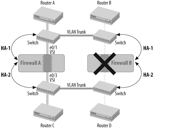
Instead of connecting the HA links directly to each other as in previous recipes, the HA links are connected via switches in a multisite configuration. Each HA link must be located on its own VLAN in such a topology so that HA data messages and control messages remain separated. Additionally, the HA-link-probe should be set. NSRP detects HA link failure via physical link state. If the Ethernet segment between data centers is disrupted, NSRP would not detect this without the use of the link probe, and the two data centers would each have an active master. Clearly this is not desirable.
Because the NSRP packets will be traversing a shared interface, it is strongly recommended that you use the authentication and encryption functions of the protocol. Apply the auth and the encrypt password to each device.
Although the majority of multisite NSRP deployments have physical Ethernet connectivity between them, this is not a hard and fast requirement. The only requirement is that the Layer 2 frames arrive at the remote peer as sent. Layer 2 VPN technologies can also provide this service over a Layer 3 infrastructure. NSRP is not connection-oriented, and is not known to have strict latency requirements.
See Also
18.14. Maintain NSRP Clusters
Solution
Use the exec nsrp sync commands:
Use theexec nsrp synccommands: FWCLUSTER:FIREWALL-A(B)->exec nsrp sync global-config saveFWCLUSTER:FIREWALL-A(B)->resetFWCLUSTER:FIREWALL-A(B)->exec nsrp sync rto ?RM Resource Manager all all realtime objects arp arp attack-db DI attack dababase auth-table auth table dhcp dhcp dip-in incoming dip table dns dns h323 H.323 l2tp l2tp mgcp MGCP calls phase1-SA IKE Phase-1 SA rpc rpc map sccp SCCP calls session session vpn vpn xlate-ctx xlate ctx table FWCLUSTER:FIREWALL-A(B)->exec nsrp sync rto all from peerFWCLUSTER:FIREWALL-A(B)->exec nsrp vsd-group id 0 mode ?backup backup ineligible ineligible init init pb primary backup
Discussion
Although NSRP should remain in sync at all times, sometimes things can get out of a synchronized state. Because NSRP should be fully synchronized to operate properly, it is a good practice to synchronize RTOs manually before maintenance, or after a reboot or other network event has occurred. You can synchronize configurations with the exec nsrp sync global-config save command. When you enter this command, the device will request the configuration from its NSRP peer and save it to flash. Then, you should reboot the device for the configuration to take effect.
You can synchronize RTOs either by category or completely. It is generally a good idea to synchronize all RTOs if you notice they are out of sync. NSRP sessions on a backup device were originally designed to have a lifetime equal to eight times that of the master upon session creation. Because of this, the number of sessions on the primary and backup devices could often differ significantly. You can use the set nsrp rto-mirror session ageout-ack command to tell the backup device to verify with the master before deleting a session. This is critically important for long-lived sessions.
When performing network maintenance, it is sometimes important to manually adjust the status of the cluster. One example of this is software upgrades. The traditional best practice for a software upgrade is to set the mode of the backup device to ineligible, or in the case of an active-active configuration, to set the master of one VSD-Group to be ineligible, then upgrade that device, manually synchronize all RTOs to the device, and then switch it over to become the master. Using the exec nsrp sync rto-mirror all from peer command, you can complete the upgrade with minimal to no downtime.
See Also
The Introduction to this chapter; Recipe 18.1