

IBM DS8900F hardware components and architecture
This chapter describes the hardware components of the IBM DS8900F. It provides insights into the architecture and individual components.
This chapter covers the following topics:
|
Note: The IBM DS8910F model 993 Rack-Mounted system has some configuration differences from the racked model 994. For more information, see IBM DS8910F Model 993 Rack-Mounted Storage System Release 9.1, REDP-5566.
|
2.1 Flash drive terminology of the DS8900F
This section describes the naming conventions that are used to describe the DS8900F components and features. Although most of these terms are introduced in other chapters of this book, they are repeated and summarized here.
2.1.1 Storage system
The term storage system in this context describes a single DS8900F (base frame plus optional expansion frame).
Base frame
The DS8900F has four available base frame models in three DS8900F families (Analytic class, Agility class, and Flexibility Class). The model numbers depend on the hardware configuration for each: DS8980F, DS8950F, and DS8910F. In this chapter, the DS8900F family name, or model number, are used interchangeably. Table 2-1 lists each of the frame models.
Table 2-1 DS8900F frame models and expansion frames
|
DS8900F
|
Base frame model
|
Expansion frame model
|
Max expansion frames
|
|
DS8980F
|
998
|
E96
|
1
|
|
DS8950F
|
996
|
E96
|
1
|
|
DS8910F
|
994
|
N/A
|
N/A
|
|
DS8910F
|
993
|
N/A
|
N/A
|
Each base frame is equipped with dual Hardware Management Consoles (HMCs).
To increase the storage capacity and connectivity, an expansion frame can be added to any DS8980F model 998, or a DS8950F model 996 with 40 cores, and at least 1 TB system memory.
To increase the storage capacity and connectivity, an expansion frame can be added to any DS8980F model 998, or a DS8950F model 996 with 40 cores, and at least 1 TB system memory.
For more information about the base frame configuration, see 2.2.5, “DS8900F base frames” on page 35.
For more information about the DS8910F model 993 Rack-Mounted system,
see IBM DS8910F Model 993 Rack-Mounted Storage System Release 9.1, REDP-5566.
see IBM DS8910F Model 993 Rack-Mounted Storage System Release 9.1, REDP-5566.
Expansion frame
The DS8980F and DS8950F support one optional expansion frame, which provides space for extra storage capacity and also supports up to two extra I/O enclosure pairs. To add an expansion frame to the DS8950F, the storage system must first be configured with 1024 GB of memory and 40 processor cores.
With these models, you can place the expansion frame up to 20 meters away from the base frame. To use this feature, use the optical Peripheral Component Interconnect Express (PCIe) I/O Bay interconnect. The Copper PCIe I/O Bay interconnect is used when the expansion frame is physically next to the base frame. For more information about the expansion frame connections, see 2.2.6, “DS8900F expansion frame” on page 38.
All DS8900F system memory and processor upgrades can be performed concurrently.
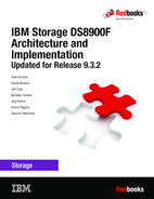
2.1.2 Management Enclosure
The Management Enclosure (ME) contains two HMC systems that provide internal network and power control communications to the central processor complexes (CPCs), I/O enclosures, and intelligent Power Distribution Units (iPDUs).
A monitor and keyboard with trackpad are provided for local management. The ME also provides up to two Ethernet connections from each HMC for remote management.
Figure 2-1 shows the front view of the 2U ME.
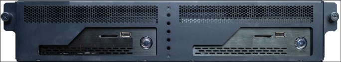
Figure 2-1 DS8900F Management Enclosure
2.1.3 Central processor complex
The DS8900F uses two POWER9-based servers, which are referred to as CPCs. Internal server, processor complex, or central electronics complex (CEC) are also sometimes used. For more information, see 2.3.1, “IBM POWER9 processor-based CPCs” on page 42.
The characteristics for CPCs for each model type are listed in Table 2-2.
Table 2-2 DS8900F processor and cache details
|
Model
|
Processors per storage system
|
Cache per storage system
|
|
998
|
Forty-four cores
|
4352 GB
|
|
996
|
Twenty cores
|
512 GB
|
|
Forty cores
|
1024 GB
| |
|
2048 GB
| ||
|
3456 GB
| ||
|
993 and 994
|
Sixteen cores
|
192 GB
|
|
512 GB
|
Both CPCs in a DS8900F system share the system workload. The CPCs are redundant, and either CPC can fail over to the other for scheduled maintenance, upgrade tasks, or if a failure occurs. The CPCs are identified as CPC 0 and CPC 1. A logical partition (LPAR) in each CPC runs the AIX V7.x operating system (OS) and storage-specific Licensed Internal Code (LIC). This LPAR is called the storage node. The storage servers are identified as Node 0 and Node 1 or server0 and server1.
2.2 DS8900F configurations and models
This section presents the DS8900F configurations and models at the time of writing.
The DS8900F consists of one base frame, and for the DS8980F or DS8950F, one optional expansion frame. The CPCs are in the base frame, and they can be upgraded with more processor cores and system memory to accommodate growing performance or when more storage capacity or host connectivity is required.
The DS8900F consists of one base frame, and for the DS8980F or DS8950F, one optional expansion frame. The CPCs are in the base frame, and they can be upgraded with more processor cores and system memory to accommodate growing performance or when more storage capacity or host connectivity is required.
The main variations between models are the combinations of CPCs, I/O enclosures, storage enclosures, and flash drives. System memory, processors, storage capacity, and host attachment upgrades from the smallest to the largest configuration can be performed concurrently.
Beginning with Release 9.3 new builds, DS8900F storage systems use machine type 5341. The former warranty and service options are now offered as part of Expert Care. Options range from a 1-year base warranty to a 5-year Expert Care Advanced or Premium.
2.2.1 DS8980F Analytic Class configuration
The DS8980F model 5341-998 is equipped with two CPCs, each with dual 11-core processors, with a maximum of 16 FC or Fibre Channel connection (IBM FICON) host adapters in the base frame and a maximum of 16 FC or FICON host adapters in a model E96 expansion frame.
Figure 2-2 shows the maximum configuration of a DS8980F with a model E96 expansion frame. The DS8950 model 996 and E96 are similar.
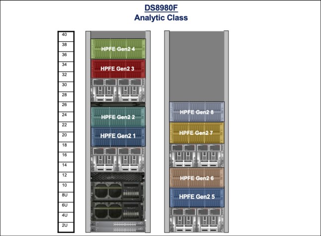
Figure 2-2 View of fully configured DS8980F or DS8950F system
Table 2-3 lists the hardware along with the minimum and maximum configuration options for the DS8980F model 998.
Table 2-3 DS8980F model 998 component list
|
Features
|
DS8980F
|
|
Rack size
|
19” 600x1050, 40U fixed
|
|
Frames min / max
|
1 / 2
|
|
CPC
|
Two IBM Power machine type and model (MTM) 9009-42A systems
|
|
I/O enclosure pairs min / max
|
1 / 4
|
|
POWER9 cores per storage system
|
44
|
|
System memory
|
4352 GB
|
|
System non-volatile storage (NVS) memory
|
128 GB
|
|
Host adapters min / max1
|
2 / 32
|
|
Host adapter ports min / max
|
8 / 128
|
|
zHyperLink adapters min / max2
|
0 / 12
|
|
Flash drives min / max
|
16 / 384
|
|
High-Performance Flash Enclosure (HPFE) Gen2 pairs min / max
|
1 / 8
|
|
Flash redundant array of independent disks (RAID) adapter pairs min / max
|
1 / 8
|
|
iPDU min / max
|
2 / 6
|
|
Power
|
Single-phase or three-phase
|
|
HMC
|
Two in ME
|
|
Ethernet switches
|
Two 8-port switches in ME, two extra 24-port switches with an E96 expansion frame
|
|
Keyboard/monitor
|
1
|
1 For more information, see 2.4.2, “I/O enclosure adapters” on page 51.
2 For more information, see Getting Started with IBM zHyperLink for z/OS, REDP-5493.
|
Note: The DS8900F hardware uses iPDUs, non-volatile dual inline memory modules (NVDIMMs) and Backup Power Modules (BPMs) to replace the internal DC-UPSs in prior generations.
|
2.2.2 DS8950F Agility Class configuration
The DS8950F model 5341-996 is equipped with two CPCs, each with either single or dual 10-core processors, with a maximum of 16 FC / FICON host adapters in the base frame and a maximum of 16 FC / FICON host adapters in the expansion frame.
Figure 2-2 on page 28 shows the maximum configuration of a DS8950F model 996 and DS8950F model E96.
Table 2-4 lists the hardware along with the minimum and maximum configuration options for the DS8950F model 996.
Table 2-4 DS8950F model 996 component list
|
Features
|
DS8950F
|
|
Rack size
|
19” 600x1050, 40U fixed
|
|
Frames min / max
|
1 / 2
|
|
CPC
|
Two IBM Power MTM 9009-42A systems
|
|
I/O Enclosure pairs min / max
|
1 / 4
|
|
POWER9 cores per system min / max
|
20 / 40
|
|
System memory min / max
|
512 GB / 3456 GB
|
|
System NVS memory min / max
|
32 GB / 128 GB
|
|
Host adapters min / max1
|
2 / 32
|
|
Host adapter ports min / max
|
8 / 128
|
|
zHyperLink adapters min / max2
|
0 / 12
|
|
Flash drives min / max
|
16 / 384
|
|
HPFE Gen2 pairs min / max
|
1 / 8
|
|
Flash RAID adapter pairs min / max
|
1 / 8
|
|
iPDU min / max
|
2 / 6
|
|
Power
|
Single-phase or three-phase
|
|
HMC
|
Two in ME
|
|
Ethernet switches
|
Two 8-port switches in ME, two extra 24-port switches with an E96 expansion frame
|
|
Keyboard/Monitor
|
1
|
1 For more information, see 2.4.2, “I/O enclosure adapters” on page 51.
2 For more information, see Getting Started with IBM zHyperLink for z/OS, REDP-5493.
2.2.3 DS8910F Flexibility Class Racked configuration
The DS8910F model 5341-994 is equipped with two CPCs, each with dual quad-core processors, with a maximum of 16 Fibre Channel (FC) / FICON host adapters, and a maximum of four zHyperLink adapters.
Figure 2-3 shows a DS8910F 994 system.
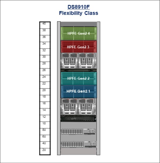
Figure 2-3 View of fully configured DS8910F model 994
Table 2-5 lists the hardware and the minimum and maximum configuration options for the DS8910F model 994.
Table 2-5 DS8910F model 994 component list
|
Features
|
DS8910F
|
|
Rack size
|
19” 600x1050, 40U fixed
|
|
Frames
|
1
|
|
CPC
|
Two IBM Power MTM 9009-22A systems
|
|
I/O bay pairs min / max
|
1 / 2
|
|
POWER9 cores per storage system
|
16
|
|
System memory min / max
|
192 GB / 512 GB
|
|
System NVS memory min / max
|
8 GB / 32 GB
|
|
Host adapters min / max1
|
2 / 16
|
|
Host adapter ports min / max
|
8 / 64
|
|
zHyperLink adapters min / max2
|
0 / 4
|
|
Flash drives min / max
|
16 / 192
|
|
HPFEs Gen2 pairs min / max
|
1 / 4
|
|
Flash RAID adapter pairs min / max
|
1 / 4
|
|
iPDU min / max
|
2 / 4
|
|
Power
|
Single-phase or three-phase
|
|
HMC
|
2 in ME
|
|
Ethernet switches
|
Two 8-port switches in ME
|
|
Keyboard/Monitor
|
1
|
1 For more information, see 2.4.2, “I/O enclosure adapters” on page 51.
2 For more information, see Getting Started with IBM zHyperLink for z/OS, REDP-5493.
2.2.4 DS8910F Flexibility Class Rack-Mounted configuration
The DS8910F Flexibility Class Rack-Mounted model 993 provides a modular rack-mountable enterprise storage system within the 5341 all-flash family.
|
Note: The DS8910F Flexibility Class Rack-Mounted system has hardware specifications that differ slightly from the rack-based models. Specific information about the model 993 can be found in IBM DS8910F Model 993 Rack-Mounted Storage System Release 9.1, REDP-5566.
|
DS8910F model 993 can be integrated into existing IBM Z models T02 or ZR1 (#0937),
IBM LinuxONE III model LT2 or LinuxONE II model LR1 (#0938), or any other standard 19-inch rack that conforms to EIA 310D specifications (#0939).
IBM LinuxONE III model LT2 or LinuxONE II model LR1 (#0938), or any other standard 19-inch rack that conforms to EIA 310D specifications (#0939).
The model 993 uses the same hardware components that are found in the rack-based DS8910 systems and offers all the same advanced features while reducing data center footprint and power infrastructure requirements.
The DS8910F model 993 is equipped with two CPCs, each with dual quad-core processors, and it can be scaled up to 96 Tier 0, Tier 1, or Tier 2 flash drives; up to 512 GB system memory and 32 host adapter ports; and four zHyperLink adapters.
Figure 2-4 shows a DS8910F Rack-Mounted model 993 system that is integrated into the z15 model T02 or LinuxONE III model LT2 that is powered by the second set of IBM Z iPDUs. DS8910F model 993 does not share a keyboard and display with the T02 or LT2 through the IBM Z KVM. Feature Codes 0611 and 0621 are required for integration of the DS8910F model 993 into a T02 or LT2.
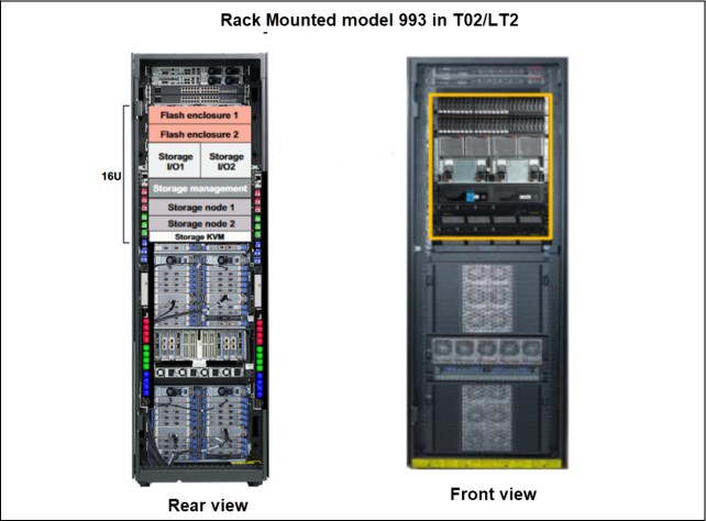
Figure 2-4 DS8910F model 993 integrated into a T02 or LT2
Figure 2-5 shows two DS8910F Rack-Mounted model 993 servers. One is integrated into the IBM z14® model ZR1 or LinuxONE II LR1 and is powered by the second set of IBM Z iPDUs (A3 and A4).
The console is shared with ZR1 or LR1 through the IBM Z KVM. Feature Codes 0610 and 0620 are required for integration of DS8910F model 993 into a ZR1 or LR1.
The other DS8910F Rack-Mounted model 993 server that is shown is the maximum configuration (two HPFE pairs) with a pair of optional iPDUs that can be integrated into a standard 19-inch rack. The DS8910F model 993 iPDUs support single or three-phase power.
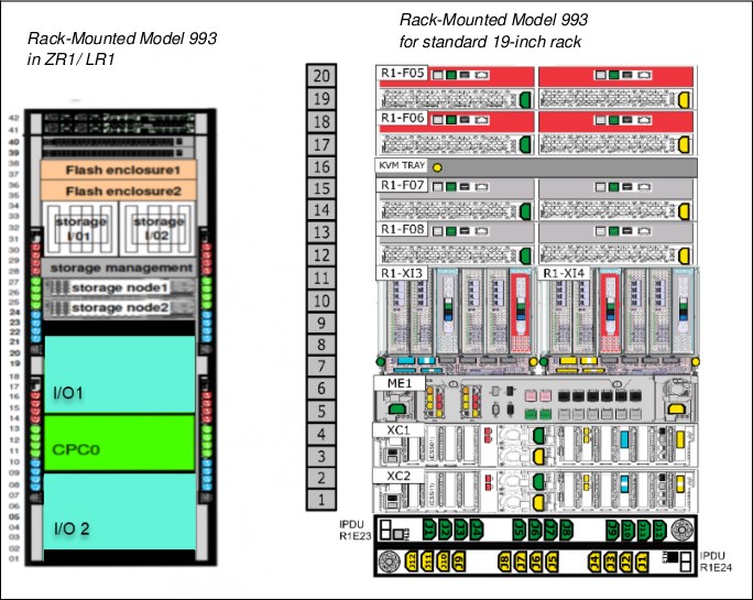
Figure 2-5 DS8910F model 993 for installation in a ZR1 or LR1 (left) and standard rack (right)
Table 2-6 lists all the hardware components and maximum capacities that are supported for the DS8910F model 993. When integrated into the entry models of IBM Z family of servers, T02, LT2, ZR1, or LR1, the DS8910F model 993 uses two IBM Z iPDUs, A3 and A4, for power. It shares the display and keyboard with ZR1 or LR1 through IBM Z KVM. It has a dedicated display and keyboard when it is integrated into a T02 or LT2.
Table 2-6 DS8910F model 993 components
|
Features
|
DS8910F model 993
|
|
Integration
|
T02, LT2, ZR1, LR1, or standard 19-inch rack space that conforms to EIA 310D
|
|
CPC
|
Two IBM Power MTM 9009-22A
|
|
I/O Enclosure pairs min / max
|
1 / 1
|
|
POWER9 cores per storage system min / max
|
16 / 16
|
|
System memory min / max
|
192 GB / 512 GB
|
|
System NVS memory min / max
|
8 GB / 32 GB
|
|
Host adapters min / max1
|
2 / 8
|
|
Host adapter ports min / max
|
8 / 32
|
|
zHyperLink adapters min / max
|
0 / 4
|
|
Flash drives min / max
|
16 / 96
|
|
HPFE Gen2 pairs min / max
|
1 / 2
|
|
Flash RAID adapter pairs min / max
|
1 / 2
|
|
iPDU
|
Two optional iPDUs with standard rack integration
|
|
Power
|
Single-phase or three-phase
|
|
HMC
|
Two in ME
|
|
Ethernet switches
|
Two 8-port switches in ME
|
|
Keyboard/Monitor
|
One with integration into T02 or LT2 and One optional with standard rack integration
|
2.2.5 DS8900F base frames
As mentioned in 2.1.1, “Storage system” on page 26, the DS8900F is available in different racked and rack-mounted models. The frame model number is determined by the configuration and the hardware version. The specific combinations are shown in Table 2-1 on page 26.
|
Note: The DS8900F models 998, 996, and 994 use a high-end 40U rack with a reduced footprint.
|
The DS8900F base racks accommodate the following components:
•Up to four HPFE Gen2 enclosure pairs in the base frame
The flash drives are installed in groups of 16, which are called installation groups. The installation groups are ordered as a set by Feature Code. Each HPFE Gen2 enclosure pair can accommodate 16, 32, or 48 flash drives.
Flash drives are available in 800 GB, 1.6 TB, 1.92 TB, 3.2 TB, 3.84 TB, 7.68 TB, and
15.36 TB capacities. For more information about HPFE, see IBM DS8000 High-Performance Flash Enclosure Gen2 (DS8000 R9.0), REDP-5422.
15.36 TB capacities. For more information about HPFE, see IBM DS8000 High-Performance Flash Enclosure Gen2 (DS8000 R9.0), REDP-5422.
All enclosures have redundant power and integrated cooling, which draws air from front to rear. For more information about cooling requirements, see Chapter 5, “IBM DS8900F physical planning and installation” on page 141.
•The rack power subsystem
The DS8900F family introduced a simplified rack power distribution system by using iPDUs that support single or three-phase power in all models. Each iPDU has its own dedicated input AC power cord. Various connector options are available for different regions.
The iPDUs are organized and installed in pairs. One iPDU pair is installed by default in each frame. A second iPDU pair is installed in the base frame when a second I/O enclosure or HPFE Gen2 pair are added. The second iPDU pair does not have to be the same type as the first pair. For more information about the iPDUs, see 2.6, “Power and cooling” on page 58.
•Management Enclosure
Each base frame includes a ME, which contains two HMCs in all DS8900F models. The ME also contains other essential management components, such as redundant network switches (used only for internal communications), Rack Power Control (RPC) cards, and the local or remote switch card. For more information about the HMC, see 2.7, “Management Console and network” on page 67.
Each base frame includes a 1U keyboard or display tray that is used to control both HMCs.
•POWER9 processor-based CPCs
Each base frame accommodates two POWER9 servers, also known as CPCs. The POWER9 servers contain the processors and memory that drive all functions to operate the DS8900F storage facility image (SFI). System memory and processor cores in the DS8900F can be upgraded concurrently. The Analytic and Agility Class DS8950F configurations run on two 4U IBM Power S924 servers. The Flexibility Class DS8910F systems use two 2U IBM Power S922 servers. For more information about the CPCs, see 2.3.1, “IBM POWER9 processor-based CPCs” on page 42.
Each CPC can accommodate an optional 10 Gbps Transparent Cloud Tiering (TCT) network adapter. For more information about slots for TCT, see 2.3.4, “Ethernet connections” on page 46.
•I/O enclosures
The DS8900F base frame accommodates a maximum of four I/O enclosures, which are installed in pairs. The first I/O enclosure pair is installed by default. The I/O enclosures provide PCIe Gen3 connectivity between the CPCs and installed I/O adapters.
The I/O enclosures house the following PCIe I/O adapters:
– Up to 16 host adapters in the base frame for a total of up to 64 host ports.
– Up to four 4-port 16 Gbps Fibre Channel Protocol (FCP) / FICON host adapters in each I/O enclosure, supporting either shortwave (SW) or longwave (LW).
– Up to four 4-port 32 Gbps encryption-capable FCP / FICON host adapters in each I/O enclosure, supporting either SW or LW.
|
Note: An intermix of 16 Gbps and 32 Gbps host adapters is supported (any combination). Intermix of SW and LW adapters is also allowed. For HA, IBM recommends installing host adapters in pairs.
|
The host adapter ports can be configured in the following manner:
• Switched Fibre Channel Protocol (FCP), which is used for open systems host attachment, and for Metro Mirror (MM) and Global Copy (GC).
• FICON for IBM Z host connectivity and also for z/OS Global Mirror (zGM).
• FCP and FICON are not supported simultaneously on the same port.
|
Note: The Fibre Channel Arbitrated Loop (FC-AL) topology is no longer supported on DS8900F host adapters.
|
– Flash RAID device adapters (DAs):
• One flash RAID adapter pair is required for each HPFE Gen2 pair.
• Each I/O enclosure pair supports up to two DA pairs.
• DA pairs connect to HPFE Gen2 pairs over eight SAS paths in a redundant dual loop topology.
– zHyperLink connections to IBM Z hosts:
• Supports direct connectivity to IBM Z at distances up to 150 m.
• zHyperLink adapters (CXP transceivers) and cables are installed in pairs within an I/O enclosure pair boundary.
• zHyperLink cables are available in lengths of 3 m (for integrated 993 models), 40 m, or 150 m. For other lengths, see IBM Z Connectivity Handbook, SG24-5444, or consult your optical cable vendor.
• High-Performance FICON (z/HPF) connectivity is required.
• zHyperLink adapter and zHyperLink cables
zHyperLink connections with IBM Z hosts provide low latency for random reads and small block sequential writes. It is a point-to-point connection, as shown in Figure 2-6.
|
Note: All DS8900F models have zHyperLink capability.
|
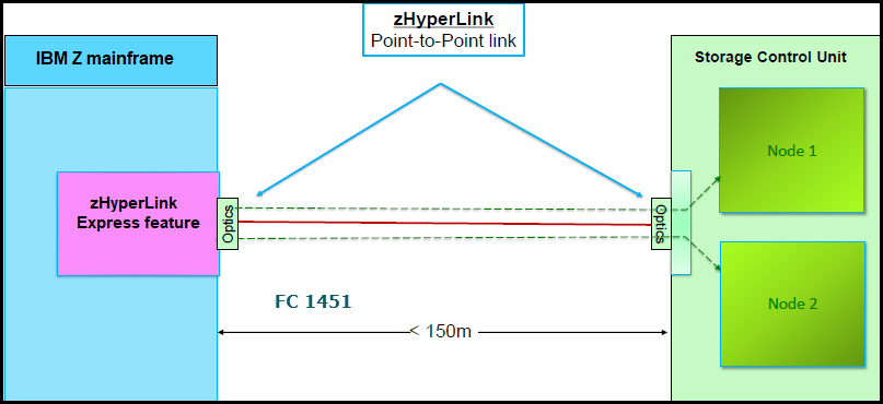
Figure 2-6 DS8900F zHyperLink connection to the system
• Each zHyperLink requires a transceiver to connect the optical zHyperLink cable to the storage system. The transceiver connects directly to an I/O enclosure CXP PCIe port, and provides connectivity for 12 transmit and receive pairs, in a multi-fiber termination push-on (MTP-24) connection. A 24x MTP-MTP cable is required for each zHyperLink connection. The transceivers are plugged into ports T3 and T4 of the I/O enclosure, as shown in Figure 2-20 on page 52.
• The number of zHyperLink adapters that can be installed into the DS8900F system depends on the number of cores per CPC. The supported combinations for zHyperLink port availability are shown in Table 2-7.
Table 2-7 zHyperLink availability for DS8900F models
|
System or model
|
Cores per CPC
(DS8900F server)
|
zHyperLink support
|
Max zHyperLink connections (increments of 2)
|
|
DS8980F Base Frame model 998
|
22
|
Yes
|
08
|
|
DS8980F model E96
|
|
Yes
|
08
|
|
DS8950F Base Frame model 996
|
10
|
Yes
|
06
|
|
20
|
Yes
|
08
| |
|
DS8950F model E96
|
|
Yes
|
08
|
|
DS8910F model 994
|
08
|
Yes
|
04
|
|
DS8910F model 993
|
08
|
Yes
|
04
|
|
Note: A maximum of 12 zHyperLink connections may be configured per DS8900F system.
|
For more information about I/O enclosures and I/O adapters, see 2.4, “I/O enclosures and adapters” on page 48.
2.2.6 DS8900F expansion frame
The Analytic and Agility class configurations support an optional model E96 40U high-end expansion frame. The supported expansion frame options are shown in Table 2-1 on page 26.
|
Note: Only the DS8980F and DS8950F models support an expansion frame.
|
All DS8980F systems support the installation of an expansion frame without any additional features. DS8950F systems require at least 20 cores per CPC and 1 TB system memory (system cache) to support the extra throughput that is provided by the installation of I/O and storage enclosures in the expansion frame.
Expansion frame components
The model E96 expansion frame accommodates the following components:
•Up to four HPFE Gen2 enclosure pairs in the expansion frame.
The flash drives are installed in groups of 16, which are called installation groups. The installation groups are ordered as a set by Feature Code. Each HPFE Gen2 enclosure pair can accommodate 16, 32, or 48 flash drives.
Flash drives are available in 800 GB, 1.6 TB, 1.92 TB, 3.2 TB, 3.84 TB, 7.68 TB, and
15.36 TB capacities. For more information about HPFE, see IBM DS8000 High-Performance Flash Enclosure Gen2 (DS8000 R9.0), REDP-5422.
15.36 TB capacities. For more information about HPFE, see IBM DS8000 High-Performance Flash Enclosure Gen2 (DS8000 R9.0), REDP-5422.
All enclosures have redundant power and integrated cooling, which draws air from front to rear. For more information about cooling requirements, see Chapter 5, “IBM DS8900F physical planning and installation” on page 141.
•The rack power subsystem.
The DS8900F family introduced a simplified rack power distribution system that uses iPDUs that support single or three-phase power in all models. Each iPDU has its own dedicated input AC power cord. Various connector options are available for different regions.
The iPDUs are ordered and installed in pairs. One iPDU pair is installed by default in each frame. For more information about iPDUs, see 2.6, “Power and cooling” on page 58.
•I/O enclosures.
The DS8950F model E96 accommodates a maximum of four I/O enclosures, which are installed in pairs. The first I/O enclosure pair is installed by default. The I/O enclosures provide PCIe Gen3 connectivity between the CPCs and installed I/O adapters.
The I/O enclosures house the following PCIe I/O adapters:
– Up to 16 host adapters in the base frame for a total of up to 64 host ports.
– Up to four 4-port 16 Gbps FCP / FICON host adapters in each I/O enclosure, supporting either SW or LW.
– Up to four 4-port 32 Gbps FCP / FICON encryption-capable host adapters in each I/O enclosure, supporting either SW or LW.
|
Note: An intermix of 16 Gbps and 32 Gbps host adapters is supported (any combination). Intermix of SW and LW adapters is also allowed. For HA, IBM recommends installing host adapters in pairs.
|
The host adapters can be configured in the following manner:
• Switched Fibre Channel Protocol (FCP), which is used for open systems host attachment, and for Metro Mirror (MM) and GC.
• FICON for IBM Z host connectivity and also for zGM.
• FCP and FICON are not supported simultaneously on the same port.
|
Note: The FC-AL topology is no longer supported on DS8900F host adapters.
|
– zHyperLink connections to IBM Z hosts:
• Supports direct connectivity to IBM Z at distances up to 150 m.
• zHyperLink adapters (CXP transceivers) and cables are installed in pairs, within an I/O enclosure pair boundary.
• zHyperLink cables are available in lengths of 3 m (for integrated 993 models), 40 m, or 150 m. For other lengths, see IBM Z Connectivity Handbook, SG24-5444, or contact your optical cable vendor.
– Flash RAID DAs:
• One flash RAID adapter pair is required for each HPFE Gen2 pair.
• Each I/O enclosure pair supports up to two DA pairs.
• DA pairs connect to HPFE Gen2 pairs over eight SAS paths in a redundant dual loop topology.
For more information, see 2.4, “I/O enclosures and adapters” on page 48.
Connecting the expansion frame
The default cable set for connecting an expansion frame contains PCIe copper cables that allow a distance of up to 2 m. This limitation requires the installation of the expansion frame next to the base frame. One cable set is required for each installed I/O enclosure pair in the expansion frame.
To ease floor planning for future expansions, an available optical PCIe cable allows a distance up to 20 m. The cable set contains optical cables and transceivers. One cable set is required for each installed I/O enclosure pair in the expansion frame.
As shown in Figure 2-7 on page 41, this extension makes the positioning of an expansion frame more flexible, especially for future capacity expansion. An extra rack side cover pair is available if needed.
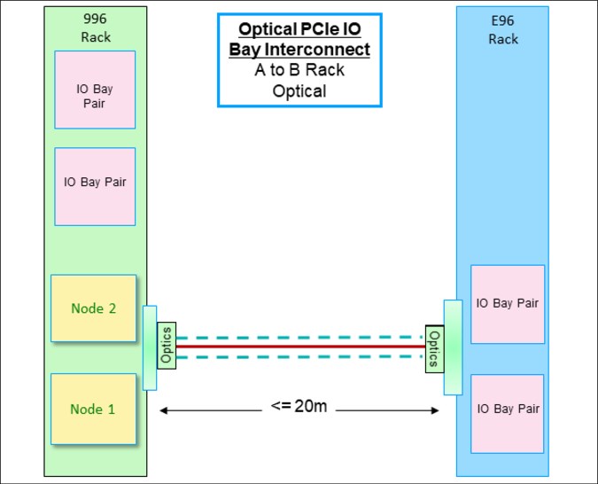
Figure 2-7 Expansion frame at a distance
2.2.7 Scalable upgrades
The hardware features that are supported in the DS8900F depend on the total system memory and total processor cores that are installed. This design ensures that the performance and capacity scale correctly. For more information about processor and system memory requirements for hardware upgrades, see Figure 2-11 on page 44. Each of the DS8900F configurations can be nondisruptively upgraded from the smallest system memory feature to the largest memory feature that is supported by that configuration.
2.2.8 Licensed functions
Several of the DS8900F functions require a license key. For more information about licensed functions, see Chapter 7, “IBM DS8900F features and licensed functions” on page 199.
2.3 DS8900F architecture overview
This section provides an architectural overview of the major components of the DS8900F:
•IBM POWER9 processor-based CPCs
•I/O enclosures and adapters
•PCIe connectivity and communication
•Storage subsystem
•Hardware management
2.3.1 IBM POWER9 processor-based CPCs
All DS8900F systems include two CPCs:
•In the DS8980F and DS8950F configurations, the CPCs are IBM Power 9009-42A servers, which have two processor sockets. The processors run in Turbo mode and typically achieve cycle speeds of 3.5 GHz.
– For the DS8980F configuration, the CPCs are populated with two 11-core processors for a combined total of 22 cores per CPC. The DS8980F CPCs support a total of
2176 GB of memory (two modules of 32 GB DDR4 NVDIMMs, two modules of 32 GB DDR4 RDIMMs, and 16 modules of 128G DDR4 RDIMMs).
2176 GB of memory (two modules of 32 GB DDR4 NVDIMMs, two modules of 32 GB DDR4 RDIMMs, and 16 modules of 128G DDR4 RDIMMs).
– For the DS8950F configuration, the CPCs are populated with one 10-core processor in the SCM-0 slot, or with two 10-core processors, for a combined total of 20 cores per CPC. The DS8950F CPCs support a maximum of 1728 GB of memory (two modules of 32 GB DDR4 NVDIMMs and 26 modules of 64 GB DDR4 RDIMMs).
•The CPCs that are used in DS8980F and DS8950F feature the following configuration:
– Two single-chip module (SCM) sockets.
– Thirty-two DDR4 dual inline memory module (DIMM) slots.
– Two BPMs.
– Three PCIe Gen4 16 lane slots with 16 lanes.
– Two PCIe Gen4 16 lane slots with eight lanes.
– Two PCIe Gen3 16 lane slots with eight lanes.
– Four PCIe Gen3 eight lane slots with eight lanes.
– One storage cage with two hard disk drives (HDDs).
– Four power supply units (PSUs).
Figure 2-8 on page 43 and Figure 2-9 on page 44 show the CPC configured for the DS8980F and DS8950F systems.
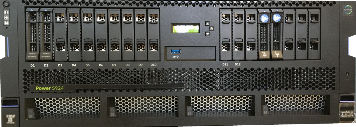
Figure 2-8 DS8980F CPC: front view
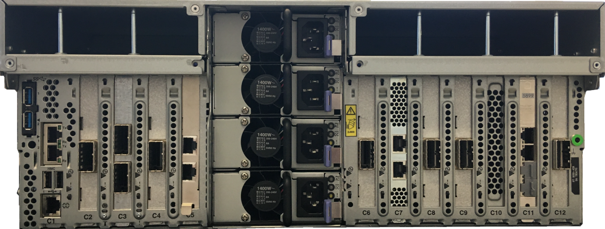
DS8980F CPC: rear view
•In the DS8910F configuration, the CPCs are IBM Power 9009-22A servers, which have two processor sockets. They are populated with two 4-core processors for a combined total of eight cores per CPC. The processors run in Turbo mode and typically achieve cycle speeds of 3.4 GHz.
The DS8910F CPCs support a maximum of 256 GB of memory (two modules of 16 GB DDR4 NVDIMMs and 14 modules of 16 GB DDR4 RDIMMs).
•The CPCs that are used in DS8910F systems feature the following configuration:
– Two SCM sockets.
– Thirty-two DDR4 DIMM slots.
– One BPM.
– Three PCIe Gen4 16 lane slots with 16 lanes.
– Two PCIe Gen4 16 lane slots with eight lanes.
– Two PCIe Gen3 16 lane slots with eight lanes.
– Two PCIe Gen3 eight lane slots with eight lanes.
– One storage cage with two HDDs.
– Two PSUs.
Figure 2-9 and Figure 2-10 show the CPC as configured in the DS8910F system.
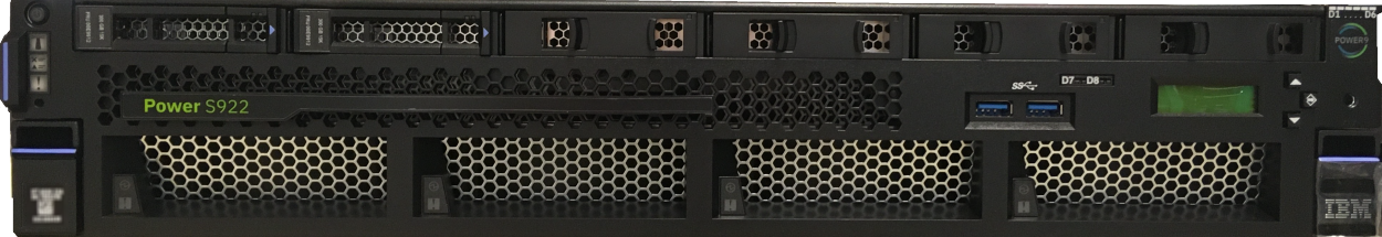
Figure 2-9 DS8910F CPC: front view
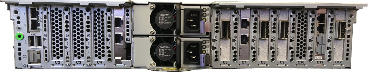
Figure 2-10 DS8910F CPC: rear view
For more information about the server hardware that is used in the DS8910F and DS8950F, see IBM Power Systems S922, S914, and S924 Technical Overview and Introduction, REDP-5497.
In the DS8900F, processor core and system memory configurations dictate the hardware that can be installed in the storage system. Processors and memory can be upgraded concurrently as required to support storage system hardware upgrades. The supported maximum system hardware components depend on the total processor and system memory configuration.
Figure 2-11 shows the supported components for the DS8900F processor and memory options. NVS values are typically 1/16th of installed system memory, except for the smallest systems with 192 GB system memory, where only 8 GB, that is, 4 GB per CPC, is used as NVS, and for the biggest systems of 3.4 or 4.3 TB memory, where NVS remains at 128 GB.
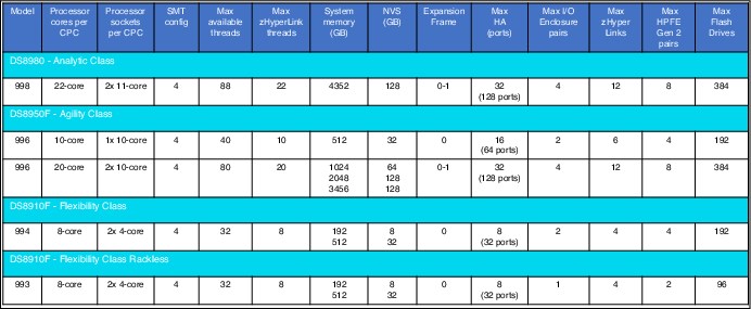
Figure 2-11 Supported components for the DS8900F processor and memory options
2.3.2 Processor memory
The DS8980F configuration comes standard with 4352 GB of total system memory. The DS8950F configuration offers up to 3456 GB of total system memory. The DS8910F Racked and Rack-Mounted configurations offer up to 512 GB of total system memory.
Each CPC contains half of the total system memory. All memory that is installed in each CPC is accessible to all processors in that CPC. The absolute addresses that are assigned to the memory are common across all processors in the CPC. The set of processors is referred to as a symmetric multiprocessor (SMP) system.
The POWER9 processor that is used in the DS8900F operates in simultaneous multithreading (SMT) mode, which runs multiple instruction streams in parallel. The number of simultaneous instruction streams varies according to processor and LIC level. SMT mode enables the POWER9 processor to maximize the throughput of the processor cores by processing multiple concurrent threads on each processor core.
The DS8900F configuration options are based on the total installed memory, which in turn depends on the number of installed and active processor cores.
The DS8980F configuration comes standard with 22 cores per server, and 4.3 TB of total system memory. No processor core or system memory upgrades are supported at the time of writing.
The following DS8950F configuration upgrades can be performed nondisruptively:
•Processor configuration upgrade from 10 cores per server to 20 cores per server
•Memory upgrade from 256 GB per server to 512 GB per server or 1024 GB per server
•Memory upgrade from 512 GB per server to 1024 GB per server or 1728 GB per server
The following DS8910F configuration upgrade can be performed nondisruptively: Memory upgrade from 96 GB per server to 256 GB per server.
|
Note: System memory and processor upgrades are tightly coupled. They cannot be ordered or installed independently from each other.
|
Caching is a fundamental technique for reducing I/O latency. Like other modern caches, the DS8900F system contains volatile memory (RDIMM) that is used as a read/write cache, and NVDIMM that is used for a persistent memory write cache. (A portion of the NVDIMM capacity is also used for read/write cache.) The NVDIMM technology eliminates the need for the large backup battery sets that were used in previous generations of DS8000. If power is lost, the system shuts down in 20 ms, but power is maintained to the NVDIMMs, and data in the NVS partition is hardened to onboard NAND flash.
NVS scales according to the processor memory that is installed, which also helps to optimize performance. NVS is typically 1/16th of installed CPC memory, with a minimum of 8 GB and a maximum of 128 GB.
2.3.3 Flexible service processor
Each POWER9 processor-based CPC is managed by a flexible service processor (FSP). The FSP is an embedded controller that is based on an IBM PowerPC® processor.
The FSP controls power and cooling for the CPC. The FSP performs predictive failure analysis (PFA) for installed processor hardware, and performs recovery actions for processor or memory errors. The FSP monitors the operation of the firmware during the boot process, and can monitor the OS for loss of control and take corrective actions.
2.3.4 Ethernet connections
Each POWER9 processor-based CPC has a single 4-port, 1 Gbps Ethernet adapter installed. On all models, the top two of these ports are connected to the internal network switches that are described in Figure 2-31 on page 68. The bottom two RJ45 copper ports can be used for TCT.
A pair of optional adapters is available for TCT as a chargeable Feature Code. Each adapter provides two 10 Gbps small form-factor pluggable plus (SFP+) optical ports for short distances, and a pair of 1 Gbps (RJ45 copper) connectors. The standard 1 Gbps Ethernet adapter is in the same slot (P1-C11) in DS8980F, DS8950F, and DS8910F systems. The optional 10 Gbps Ethernet adapter is in the P1-C10 slot for DS8980F and DS8950F systems, and is in the P1-C4 slot in DS8910F systems. For more information about TCT,
see IBM DS8000 Transparent Cloud Tiering (DS8000 Release 9.2), SG24-8381.
see IBM DS8000 Transparent Cloud Tiering (DS8000 Release 9.2), SG24-8381.
Figure 2-12 shows the location codes of the CPCs in DS8980F and DS8950F systems. Figure 2-13 on page 47 shows the location codes of the CPC in a DS8910F system.
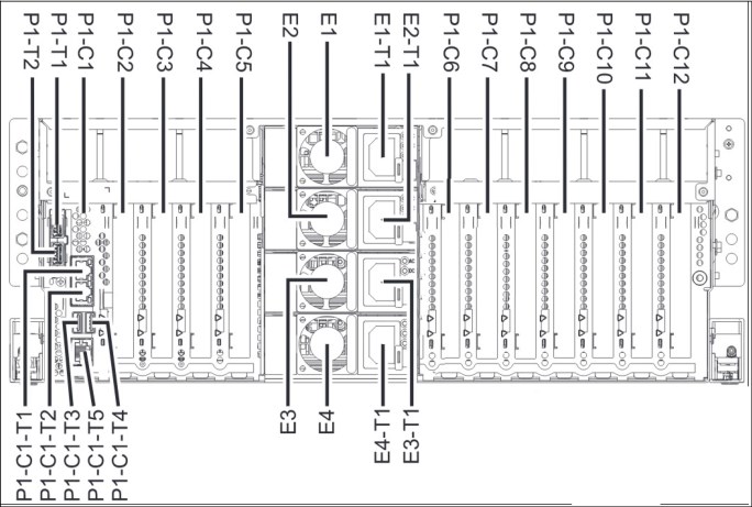
Figure 2-12 Location codes of the CPC in DS8980F and DS8950F systems in the rear
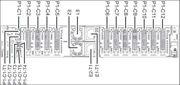
Figure 2-13 Location codes of the CPC in the DS8910F system in the rear
2.3.5 Peripheral Component Interconnect Express adapters
Each DS8900F CPC contains multiple PCIe adapters. These adapters enable point-to-point connectivity between CPCs, and I/O enclosures. Depending on the configuration, up to seven PCIe adapters are in each DS8900F CPC.
A DS8900F CPC is equipped with the following PCIe adapters:
•The DS8980F system has six single-port PCIe adapters in slots C2, C4, C6, C8, C9, and C12, and one 2-port PCIe adapter in slot C3.
•The DS8950F system has two different processor configurations for PCIe adapters:
– Single 10-core CPC maximum configuration for one frame has four single-port PCIe adapters in slots C6, C8, C9, and C12.
– Dual 10-core CPC maximum configuration for two frames has six single-port PCIe adapters in slots C2, C4, C6, C8, C9, and C12, and one 2-port PCIe adapter in slot C3.
•The DS8910F model 994 has four single-port PCIe adapters in slots C6, C8, C9, and C12.
•The DS8910F model 993 has two single-port PCIe adapters in slots C6 and C12.
Figure 2-14 shows the PCIe adapter locations in the DS8980F CPC. Figure 2-15 shows the PCIe adapter locations in the DS8910F CPC.
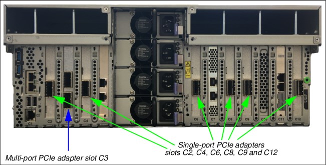
Figure 2-14 PCIe adapter locations in the DS8980F and DS8950F CPC: rear view
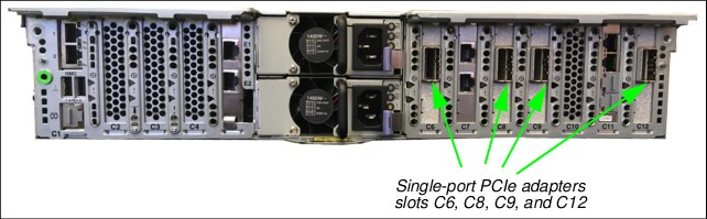
Figure 2-15 PCIe adapter locations in the DS8910F CPC: rear view
2.4 I/O enclosures and adapters
The DS8900F base frame and expansion frame (if installed) contain I/O enclosures, which are installed in pairs.
The I/O enclosures are PCIe Gen3-capable, and are attached to the CPCs with 8-lane PCIe Gen3 cables. The I/O enclosures have six PCIe adapter slots, plus six CXP connectors.
•DS8980 and DS8950F CPCs have up to six 1-port and one 2-port PCIe adapters that provide connectivity to the I/O enclosures.
•DS8910F CPCs have up to four 1-port PCIe adapters that provide connectivity.
Figure 2-16 on page 49 - Figure 2-18 on page 50 show the DS8900F CPC to I/O enclosure connectivity.
The DS8980 configuration requires no extra features to support an expansion frame.
The DS8950F configuration requires two 10-core processors per CPC and 1 TB system memory to support an expansion frame.
One or two I/O enclosure pairs can be installed in the base frame of the DS8900F and also in the E96 expansion frame. Each I/O enclosure can have up to four host adapters. A maximum of 16 host adapter ports are supported in a single I/O enclosure. The I/O enclosure has two zHyperLink connections. For more information about zHyperLink availability for DS8900F models, see Table 2-7 on page 38.
|
Note: Model 993 supports one pair of I/O enclosures.
|
Each I/O enclosure has the following characteristics:
•Half-width 5U rack-mountable enclosure
•Six PCIe slots (four for host adapters, two for flash RAID adapters)
•Two PCIe connections to the CPCs
•Two zHyperLink connections
•Two PCIe Gen3 connections (unused)
•Redundant power and cooling
Figure 2-16 shows the DS8980F and DS8950F CPC to I/O enclosure connectivity.
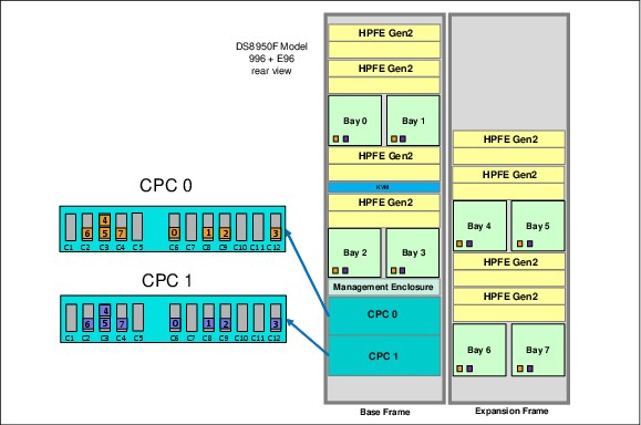
Figure 2-16 DS8980F and DS8950F I/O enclosure connections to the CPCs
Figure 2-17 shows the DS8910F model 994 CPC to I/O enclosure connectivity.
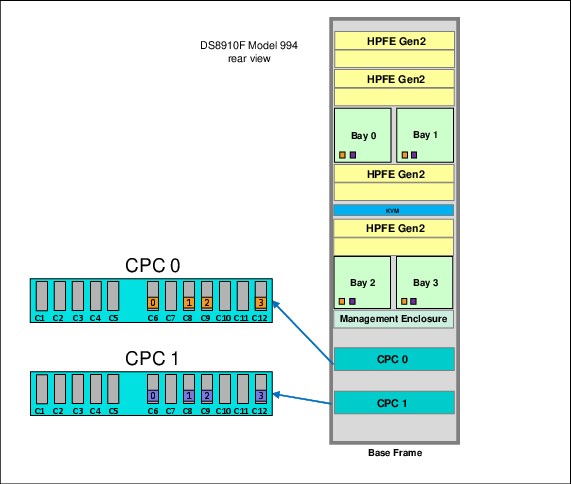
Figure 2-17 DS8910F model 994 I/O enclosure connections to the CPC
Figure 2-18 shows the DS8910F model 993 CPC to I/O enclosure connectivity.
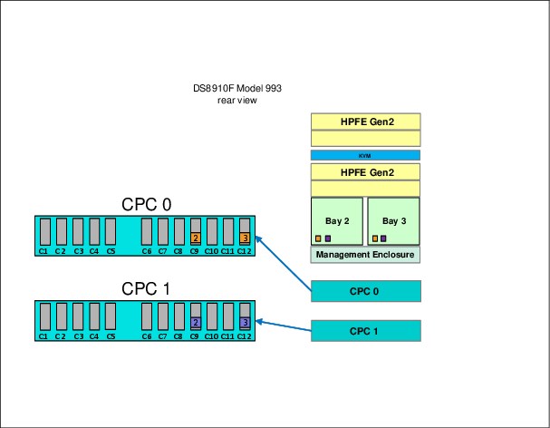
Figure 2-18 DS89010F model 993 I/O enclosure connections to the CPC
2.4.1 Cross-cluster communication
Figure 2-19 shows how the DS8900F I/O enclosure hardware is shared between the servers. One CPC is on the left side and one CPC is on the right side, and the diagram shows the SCMs (SCM #0 and SCM#1). The solid lines denote primary PCIe paths, and the dashed lines denote secondary PCIe paths.
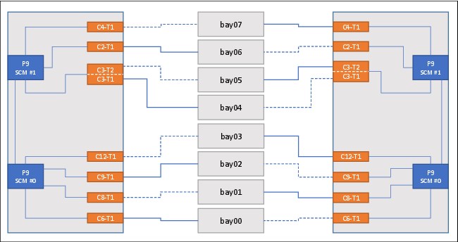
Figure 2-19 DS8900F series PCIe communications paths
The DS8900F uses the PCIe paths through the I/O enclosures to provide high-speed communication paths between the CPCs. Normally, the lowest available even-numbered I/O enclosure is used for communication from server 0 to server 1, and the lowest available odd-numbered I/O enclosure is used for communication from server 1 to server 0.
If a failure occurs in one or more I/O enclosures, any of the remaining enclosures can be used to maintain communication between the servers.
2.4.2 I/O enclosure adapters
The DS8900F I/O bay provides the connectivity from the host systems to the storage arrays through the CPCs. Each I/O adapter is optimized for its specific task.
The I/O bay can contain up to four host adapters that provide attachment to host systems and up to two flash RAID DAs to provide attachment to the HPFE Gen2 enclosures. Each I/O bay has six PCIe x8 CXP connectors on the I/O bay PCIe module. Two ports (T1 and T2) are for the internal PCIe fabric connections to CPC 0 and CPC 1. Two ports (T3 and T4) are for attachment of zHyperLink to IBM Z and two ports (T5 and T6) are unused.
Figure 2-20 shows the DS8900F I/O bay adapter layout.
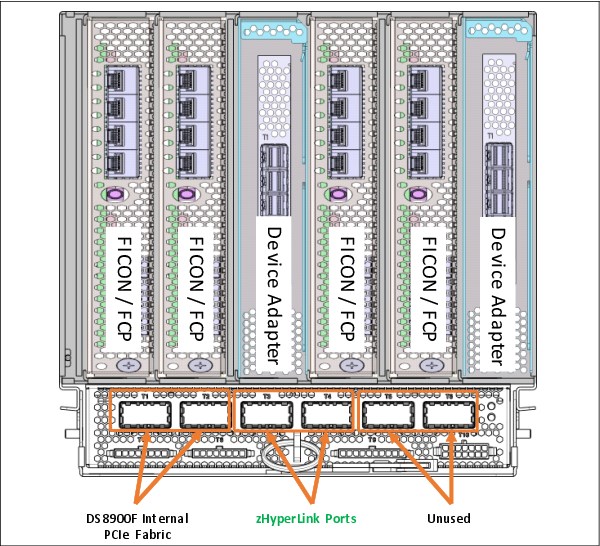
Figure 2-20 DS8900F I/O bay adapter layout
DS8900F host adapters
Attached host servers interact with software that is running on the CPCs to access data that is stored on logical volumes. The CPCs manage all read/write requests to the logical volumes on the storage arrays.
Two different types of host adapters are available: 32 Gbps and 16 Gbps. Both have four ports. The 32 Gbps adapters can auto-negotiate their data transfer rate down to 8 Gbps full-duplex data transfer. The 16 Gbps adapters can auto-negotiate down to 4 Gbps full-duplex data transfer.
Figure 2-21 on page 53 shows the 32 Gbps FCP or FICON host adapter. It provides faster single stream and per-port throughput and reduces latency compared to the 16 Gbps adapter. The 32 Gbps host adapter is equipped with a quad-core 2 GHz PowerPC processor that delivers dramatic (2 - 3 times) full adapter I/O operations per second (IOPS) improvements compared to the 16 Gbps adapter. The 32 Gbps adapter is required to enable IBM Fibre Channel Endpoint Security encryption.
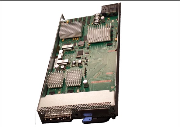
Figure 2-21 32 Gbps FCP or FICON host adapter
The 16 Gbps host adapter supports only IBM Fibre Channel Endpoint Security authentication.
The 32 Gbps host adapter supports both IBM Fibre Channel Endpoint Security authentication and line-rate encryption.
For more information, see IBM Fibre Channel Endpoint Security for IBM DS8900F and IBM Z, SG24-8455.
Both adapters contain a high-performance application-specific integrated circuit (ASIC). To ensure maximum data integrity, it supports metadata creation and checking. Each FC port supports a maximum of 509 host login IDs and 1,280 paths. This configuration enables the creation of large storage area networks (SANs).
Each host adapter port can be configured as either FICON or FCP. For both host adapters, the adapter optics can be either LW or SW.
The DS8980F and DS8950F configurations support a maximum of 16 host adapters in the base frame and 16 extra host adapters in the model E96 expansion frame. The DS8910F model 994 configuration supports a maximum of 16 host adapters. The DS8910F model 993 configuration supports a maximum of eight host adapters.
Host adapters are installed in slots 1, 2, 4, and 5 of the I/O enclosure. Figure 2-20 on page 52 shows the locations for the host adapters in the DS8900F I/O enclosure. The system supports an intermix of both adapter types up to the maximum number of ports, as shown in Table 2-8.
|
Optimum availability: To obtain optimum availability and performance, one host adapter must be installed in each available I/O enclosure before a second host adapter is installed in the same enclosure.
|
Table 2-8 DS8900F port configurations
|
Model
|
Min/Max host adapters
|
Min/Max host adapter ports
|
Max zHyperLink adapters
|
|
998
|
2/16
|
8/64
|
8
|
|
998+E96
|
2/32
|
8/128
|
121
|
|
996
|
2/16
|
8/64
|
6/82
|
|
996 + E96
|
2/32
|
8/128
|
12a
|
|
994
|
2/16
|
8/64
|
4
|
1 Maximum of eight in either the base frame or the expansion frame. Maximum of 12 per system.
2 Maximum of six with 10-core processors per CPC, and eight with 20-core processors per CPC.
Table 2-9 shows the preferred host adapter installation order for the DS8900F system. The host adapter locations and installation order for the four I/O enclosures in the base frame are the same for the I/O enclosures in the first expansion frame.
Table 2-9 DS8900F host adapter installation order
|
I/O bay
|
Slot number
| |||||
|
C1
|
C2
|
C3
|
C4
|
C5
|
C6
| |
|
For two I/O enclosures (all models)
| ||||||
|
Bottom I/O bay 02 / 06
|
3
|
7
|
|
1
|
5
|
|
|
Bottom I/O bay 03 / 07
|
2
|
6
|
|
4
|
8
|
|
|
For four I/O enclosures (Model 998, Model 996, Model 994 Model E961)
| ||||||
|
Top I/O bay 00 / 04
|
7
|
15
|
|
3
|
11
|
|
|
Bottom I/O bay 02 / 06
|
5
|
13
|
|
1
|
9
|
|
|
Top I/O bay 01 / 05
|
4
|
12
|
|
8
|
16
|
|
|
Bottom I/O bay 03 / 07
|
2
|
10
|
|
6
|
14
|
|
1 For the DS8950F model E96, the enclosure numbers are in emphasized text, and the plug order is the same as the other models.
Fibre Channel
The DS8900F uses the Fibre Channel Protocol (FCP) to transmit Small Computer System Interface (SCSI) traffic inside FC frames. It also uses FC to transmit FICON traffic for IBM Z I/O.
Each of the ports on a DS8900F host adapter can be configured for FCP or FICON, but a single port cannot be configured for both concurrently. The port topology can be changed by using the DS GUI or DS CLI.
Fibre Channel-supported servers
The current list of servers that are supported by FC attachment can be found at the IBM System Storage Interoperation Center (SSIC) website.
Fibre Channel distances
All ports on each adapter must be either LW or SW. The two types cannot be intermixed within a single adapter. With LW, you can connect nodes at distances of up to 10 km
(6.2 miles) non-repeated. With SW, you are limited to a distance that depends on the FC cable type and the data transfer rate. For 16 Gbps and 32 Gbps, use OM3 or OM4. For the link distance limitations, see Table 2-10.
(6.2 miles) non-repeated. With SW, you are limited to a distance that depends on the FC cable type and the data transfer rate. For 16 Gbps and 32 Gbps, use OM3 or OM4. For the link distance limitations, see Table 2-10.
Table 2-10 SW link distance
|
Speed
|
OM3 link distance
|
OM4 link distance
|
|
16 Gbps
|
100 m (328 ft.)
|
125 m (410.1 ft.)
|
|
32 Gbps
|
70 m (229.6 ft.)
|
100 m (328 ft.)
|
Flash RAID adapters
Flash RAID adapters, also known as DAs, provide redundant access to the internal storage devices. Each DA manages a pair of HPFE Gen2 enclosures. The adapters are always installed as a pair. Logical configuration is then balanced across the DA pair for load-balancing and the highest throughput.
The DAs are installed in the I/O enclosures and are connected to the CPCs through the PCIe network. The DAs are responsible for managing and monitoring the flash RAID arrays. The DAs provide remarkable performance because of a high-function and high-performance ASIC. To ensure maximum data integrity, the adapter supports metadata creation and checking.
For more information about the flash RAID adapters, see IBM DS8000 High-Performance Flash Enclosure Gen2 (DS8000 R9.0), REDP-5422.
2.5 Flash drive enclosures
The DS8900F is equipped with HPFE Gen2 storage enclosures:
•Flash enclosure pairs connect to flash RAID DAs by using SAS cabling.
•Flash RAID DAs are installed in the C3 and C6 slots of I/O enclosures.
HPFE Gen2 enclosures are always installed in pairs. Each enclosure pair supports 16, 32, or 48 flash drives. A single Gen2 enclosure is shown in Figure 2-22.
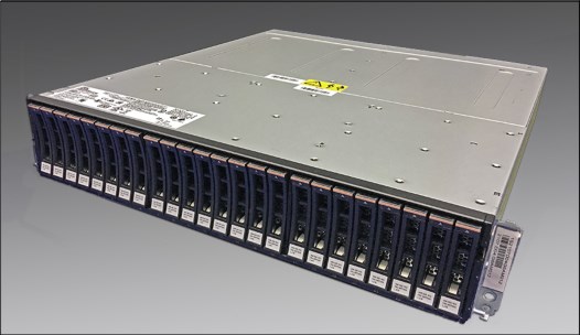
Figure 2-22 HPFE Gen2 enclosure
Each HPFE Gen2 pair is connected to a redundant pair of Flash-optimized RAID controllers. The PCIe flash RAID adapters are installed in the DS8900F I/O enclosures.
The DS8980F and DS8950 configurations can support up to four HPFE Gen2 pairs in the base frame, and up to four HPFE Gen2 pairs in the expansion frame for a total of eight HPFE Gen2 pairs, with a maximum of 384 flash drives.
To learn more about the HPFE Gen2, see IBM DS8000 High-Performance Flash Enclosure Gen2 (DS8000 R9.0), REDP-5422.
Flash drives in the HPFE Gen2
Each HPFE Gen2 pair can contain 16, 32, or 48 flash drives. Flash drives are available in
800 GB, 1.6 TB, 1.92 TB, 3.2 TB, 3.84 TB, 7.68 TB, or 15.36 TB capacities. All flash drives in an HPFE Gen2 enclosure pair must be of the same type (high performance or high capacity).
800 GB, 1.6 TB, 1.92 TB, 3.2 TB, 3.84 TB, 7.68 TB, or 15.36 TB capacities. All flash drives in an HPFE Gen2 enclosure pair must be of the same type (high performance or high capacity).
Flash drive sets
Flash drives are ordered in drives sets of 16. The HPFE Gen2 pair can contain 16, 32, or 48 flash drives (1, 2, or 3 drive sets). Half of the drive set is installed in each enclosure of the pair.
Storage-enclosure fillers
Storage-enclosure fillers occupy empty drive slots in the storage enclosures. The fillers ensure consistent airflow through an enclosure. For HPFE Gen2, one filler feature provides a set of 16 fillers.
High-performance flash drives
The DS8900F system supports 2.5-inch high-performance flash drives, which are designated as Flash Tier 0 (see Table 2-11). All high-performance flash drives are Full Disk Encryption (FDE) capable. For more information about licensed features, see Chapter 7, “IBM DS8900F features and licensed functions” on page 199.
Table 2-11 Supported high-performance flash drives
|
Feature Code
|
Drive capacity
|
Drive type
|
RAID support
(Default RAID 6)
|
|
1611
|
800 GB
|
2.5-in flash tier 0
|
5, 6, and 101
|
|
1612
|
1.6 TB
|
2.5-in Flash Tier 0
|
6 and 10
|
|
1613
|
3.2 TB
|
2.5-in Flash Tier 0
|
6 and 10
|
1 RAID 5 is supported, but not recommended.
|
Note: To learn more about the DS8900F drive features, see the IBM System Storage DS8900F Introduction and Planning Guide, SC27-9560.
|
High-capacity flash drives
The DS8900F system also supports 2.5-inch high-capacity flash drives (see Table 2-12). All high-capacity flash drives are FDE-capable. 3.84 TB drives are designated as Flash Tier 1, while 1.92 TB, 7.68 TB, and 15.36 TB drives are designated as Flash Tier 2.
Table 2-12 Supported high-capacity flash drives
|
Feature Code
|
Drive capacity
|
Drive type
|
RAID support
(Default RAID 6)
|
|
1623
|
3.84 TB
|
2.5-in. Flash Tier 1
|
6, 10
|
|
1622
|
1.92 TB
|
2.5-in. Flash Tier 2
|
6, 10
|
|
1624
|
7.68 TB
|
2.5-in. Flash Tier 2
|
6, 10
|
|
1625
|
15.36 TB
|
2.5-in. Flash Tier 2
|
6, 10
|
Arrays and spares
Each HPFE Gen2 pair can contain up to six array sites. Each set of 16 flash drives creates two 8-drive array sites. During logical configuration, RAID 6 arrays are created by default on each array site, and the required number of spares are created. Each HPFE Gen2 pair always has two global spares, which are created from the first increment of 16 flash drives. For RAID 6 arrays, the first two arrays that are created from these array sites are 5+P+Q+S. Subsequent RAID 6 arrays in the same HPFE Gen2 Pair are 6+P+Q.
|
Note: For all drive types, RAID 6 is the default in DS GUI and DS CLI, but RAID 10 is optional. For flash drives smaller than 1 TB, RAID 5 is also optional, but is not recommended.
|
System capacity limitations
There are capacity limitations depending on the use of small or large extents. The maximum amount of usable and provisioned capacities from small and large extents depend on the amount of system cache, as shown in Table 2-13.
Table 2-13 Maximum usable and provisioned capacity based on system cache size
|
Cache
|
Max. usable size with large extents
|
Max. provisioned size with large extents
|
Max. usable size with small extents
|
Max. provisioned size with small extents
|
|
Less than or equal to 512 GB
|
Fixed-Block (FB): 4096 TiB
Count Key Data (CKD): 3652 TiB
|
FB: 4096 TiB
CKD: 3652 TiB
|
FB: 512 TiB
CKD: 551 TiB
|
FB: 1024 TiB
CKD: 913 TiB
|
|
Greater than 512 GB
|
FB: 16384 TiB
CKD: 14608 TiB
|
FB: 8160 TiB - 16384 TiB1
CKD: 7263 TiB - 14608 TiBa
|
FB: 2048 TiB
CKD: 2205 TiB
|
FB: 3968 TiB - 4096 TiBa
CKD: 3538 TiB - 3652 TiBa
|
1 The exact value within the range is determined by a complex calculation that is based on the number of volumes and volume sizes. You should conservatively plan for configurations targeting the low end of the range.
Table 2-14 shows the maximum number of flash drives and maximum raw storage capacity for the different models.
Table 2-14 Maximum raw storage capacity per model
|
Model/Processors
|
System memory
(GB) |
Maximum flash drives
|
Maximum raw storage capacity1
|
|
DS8980F / 22-core
|
4 352
|
384
|
5 898 TB
|
|
DS8950F / 10-core
|
512
|
192
|
2 949 TB
|
|
DS8950F / 20-core
|
1 024
2 048
3 456
|
384
|
5 898 TB
|
|
DS8910F / 8-core
|
192
512
|
192
|
2 949 TB
|
1 Using 15.36 TB Flash Tier 2 drives.
2.6 Power and cooling
The DS8900F power and cooling systems are highly redundant. The components are described in this section. For more information, see 3.6, “RAS on the power subsystem” on page 97.
2.6.1 Rack power control cards
The DS8900F features a pair of redundant rack power control cards (RPCs), which monitor hardware conditions and provide control paths to the I/O enclosures and LED indicators in the storage system. The RPCs are housed in the ME and get their power from the ME redundant PSUs. The RPCs are hardware-based system management controllers with their own firmware and code.
As in earlier DS8000 models, the DS8900F RPCs are connected to the FSPs in each CPC by using serial Inter-Integrated Circuit (I2C) cables and to all I/O enclosures in the base and expansion rack over daisy-chained Power Control Network (PCN) connections.
RPCs also communicate with each of the CPC operating LPARs over RS485 serial connections. Using this communication path, the RPCs act as a quorum in the CPC or LPAR cluster communication to avoid cluster splits in a quorum or RPC race.
|
Important: Unlike earlier DS8000 models, DS8900F RPCs normally provide for only communication and connectivity to components in the storage system. Power control functions are managed by the HMCs.
|
2.6.2 Intelligent Power Distribution Units
The usage of NVDIMMs for write cache retention allows DS8900F to greatly simplify rack power distribution. Bulky DC-UPS battery backup systems are replaced by compact intelligent power distribution units (iPDUs) that significantly reduce the rack footprint and weight.
The iPDUs are available in single or three-phase power configurations in all models. Each iPDU has one AC power connector and a dedicated inline power cord. Output power is provided by 12 C13 power outlets with circuit breaker protection.
Figure 2-23 shows the iPDU connections.
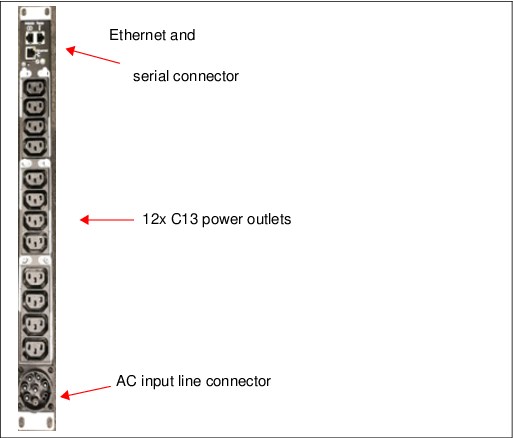
Figure 2-23 iPDU connections
iPDUs are installed in pairs. Each DS8900 rack has a minimum of one iPDU pair. For models 988, 986, and 984, a second pair may be installed in the base frame to provide power for more I/O and storage enclosures.
DS8900F can tolerate a power line disturbance (PLD) of up to 20 ms. If the PLD exceeds this threshold on both sides of the power domain, the system initiates an orderly shutdown, and data in write cache is saved to flash memory in the NVDIMMs. The NVDIMMs remain functional, even if the system has a complete power outage. For more information about NVDIMMs, see 2.6.5, “Backup Power Modules and NVDIMM” on page 65.
The iPDUs are managed by using the black and gray internal private networks. Each of the outlets can be individually monitored, and powered on or off. The iPDUs support Simple Network Management Protocol (SNMP), telnet, and a web interface.
DS8900F HMCs are responsible for system power control and monitoring by communicating to the network interfaces of the iPDUs and RPCs.
HMCs provide control and monitoring of the following items:
•AC power ON/OFF the whole system
•iPDU configuration
•iPDU health checking and error reporting
•Collecting power usage statistical data
•Controlling single power outlets during service actions
•iPDU firmware update
Figure 2-24 shows the Ethernet connections of the optional iPDUs for a DS8910F model 993. The ME provides the Ethernet ports for the iPDU Ethernet interfaces.
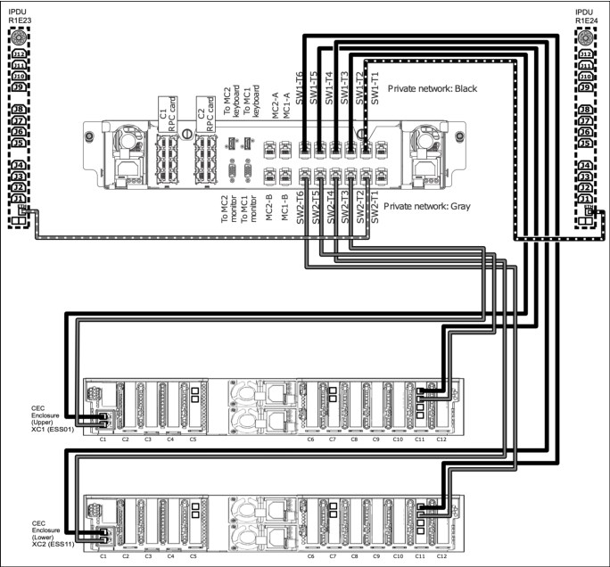
Figure 2-24 DS8910F model 993 iPDU Ethernet connections
Figure 2-25 shows the Ethernet connections of the iPDUs for a DS8910F model 994, which is equivalent to the iPDU configuration on a DS8980F or DS8950F without an expansion frame. All Ethernet ports of the ME private black and gray network are now occupied.
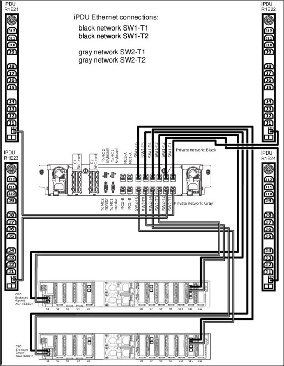
Figure 2-25 DS8910F model 994 iPDU Ethernet connections
Figure 2-26 on page 63 shows an example how the power is distributed when two iPDU pairs are installed. Note the power connections of a second HPFE Gen2 storage enclosure or the second I/O enclosure pair.
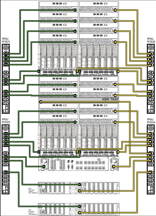
Figure 2-26 DS8910F model 994 iPDU power connections
Adding a model E96 expansion frame to a DS8980F or DS8950F system also adds another iPDU pair in that frame, which requires Ethernet connections to the internal management networks. To provide these connections, two extra Ethernet switches are installed in the base frame. This switch pair feature must be ordered with the expansion frame.
Figure 2-27 shows the two required network switches and the Ethernet connections for an expansion frame and three connected iPDU pairs.
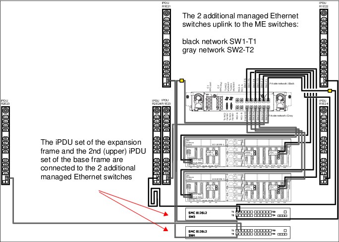
Figure 2-27 DS8950F model 996 and model E96 Ethernet connections
2.6.3 Power domains
To provide redundant power, the iPDUs are organized into groups that are called power domains. As shown in Figure 2-26 on page 63 and Figure 2-27, the iPDUs on one side of the racks form a power domain. If you look at the rear of the storage system, the iPDUs on the left side of the racks are in one domain (green), and the iPDUs on the right side of the racks are in the other (yellow) power domain.
The redundant power supplies in the CPCs, I/O enclosures, HPFE Gen2 enclosures, and the ME are connected across both power domains. The left power supplies connect to the green domain, while the right power supplies connect to the yellow domain.
For full redundancy, each power domain must be connected to separate power distribution systems that are fed by independent building power sources or service entrances.
2.6.4 Rack management 24-port Ethernet switch pair
When an expansion frame is ordered, an extra Ethernet switch pair is required to provide internal network connectivity to all installed iPDUs. The switches are installed at the bottom of the base frame. The two extra switches are called SW3 and SW4. One switch uplinks to the black and one to the gray network switch in the ME. For more information about connecting iPDUs for Ethernet management, see 2.6.2, “Intelligent Power Distribution Units” on page 59.
2.6.5 Backup Power Modules and NVDIMM
In DS8900F systems, system memory consists of RDIMMs for read/write cache memory, and NVDIMMs, which contain the write NVS partitions. A portion of the NVDIMM capacity is also accessed as ordinary read/write cache. The NVDIMM Persistent Memory Write Cache design eliminates the need for DC-UPSs and bulky battery sets, thus reducing the footprint of the DS8900 racks.
During normal operation, the NVDIMMs behave like any other DRAM, but when a power outage or other system failure occurs, the NVS partition contents are hardened in NAND flash storage. This NAND flash storage is with the DRAM chips on the NVDIMM module. The content is encrypted when written to the flash storage to prevent unauthorized access to the contents. Storing the write cache data in flash chips replaces the need for a fire hose dump, which was used on earlier DS8000 models to harden NVS data to disk. Figure 2-28 shows a symbolic view of an NVDIMM module.
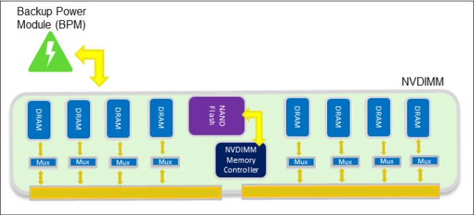
Figure 2-28 NVDIMM logic
BPMs connect directly to the NVDIMM modules to provide power during the DRAM to flash operation. They are specific nickel-based hybrid energy storage modules with a high-power discharge and fast charge times of 3 - 15 minutes. When system power is restored, the NVDIMMs move the preserved data from flash back to DRAM to be destaged to the storage system arrays during initial microcode load (IML).
The POWER9 processor-based systems support two NVDIMMs per CPC in designated memory slots.
The size of a BPM is smaller than a standard 2.5-inch disk drive module (DDM) and fits into one of the free CPC disk drive bays. A maximum of two BPMs are installed per CPC.
Figure 2-29 shows an example of a BPM.
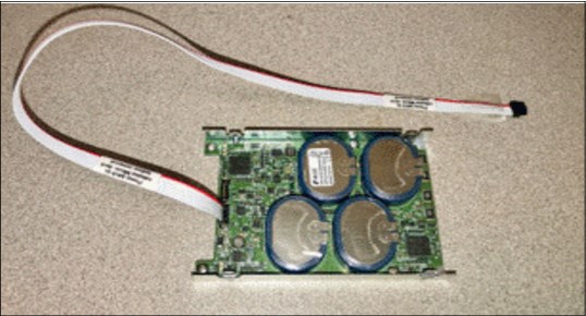
Figure 2-29 Backup Power Module
With the BPMs connected directly to the NVDIMMs, the DRAM to flash operation functions independently without the need for any power that is provided by the CPC.
The NVDIMM capability is in addition to the data protection concept of storing the write cache NVS on the alternative node. For more information, see 3.2, “CPC failover and failback” on page 78.
NVDIMM configurations use either two 16 GB or two 32 GB modules. NVDIMMs are always installed in pairs of the same size. With 16 GB NVDIMMs, one BPM is sufficient to provide power to both modules in one CPC. With 32 GB NVDIMMs, two BPMs are provided in each CPC, with one for each NVDIMM.
2.6.6 Power cord options
The power cord must be ordered for a specific input voltage and connector type to meet local requirements, and these requirements vary worldwide. In cases where the supplied power cord does not include a connector, the proper connector must be installed by an electrician after the system is delivered. For more information, see the IBM System Storage DS8900F Introduction and Planning Guide, SC27-9560.
2.6.7 Enclosure power supply units
The CPCs, I/O enclosures, ME, and HPFE Gen2 enclosures have redundant PSUs for each enclosure that are fed by both left and right-side iPDUs. Left and right-side iPDUs should be fed by independent power distribution sources whenever possible. The PSUs have their own internal cooling fans. Each enclosure also has its own redundant cooling fans. All fans draw cool air from the front of the frame and exhaust hot air to the rear of the frame.
|
Note: The DS8900F is designed for efficient air flow and to be compliant with hot and cold aisle data center configurations.
|
2.7 Management Console and network
Every DS8900F base frame is equipped with a ME that includes two small form-factor (SFF) mini-PC HMCs, and two private network Ethernet switches. The secondary HMC is a redundant point of management in the DS8900F and it sits next to the primary HMC.
Figure 2-30 shows a diagram of the mini-PC HMCs and keyboard and monitor drawer location in the DS8950F model 996 base frame.
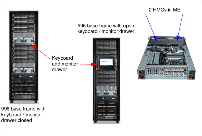
Figure 2-30 Diagram of mini-PC HMC and keyboard and monitor drawer location in the DS8950F
The storage administrator runs all DS8900F logical configuration tasks by using the Storage Management GUI or DS CLI. All client communications to the storage system are through the HMCs.
Clients that use the DS8900F advanced functions, such as MM or FlashCopy, communicate to the storage system with IBM Copy Services Manager.
The HMCs provide connectivity between the storage system and external Encryption Key Manager (EKM) servers.
HMCs also provide remote Call Home and remote support connectivity.
For more information about the HMC, see Chapter 6, “IBM DS8900F Management Console planning and setup” on page 167.
2.7.1 Ethernet switches
The DS8900F base frame has two 8-port Ethernet switches in the ME. The two switches provide redundant connectivity for the black and gray private management networks. The FSPs and LPARs in each CPC have dual network connections, with each connecting to the black and gray switches through the external breakout ports at the rear of the ME.
The switches receive power from the PSUs inside the ME and do not require separate power outlets. The ports on these switches are shown in Figure 2-31.
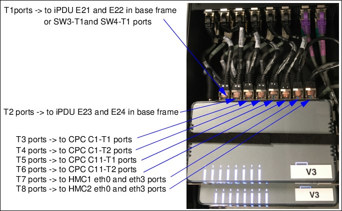
Figure 2-31 Eight-port Ethernet switches (SW1 and SW2) in the Management Enclosure
Each HMC also uses two designated Ethernet interfaces for the internal black (eth0) and gray (eth3) networks. Because the HMCs are installed in the ME, they are connected directly to the switches without routing through the external breakout ports.
The black and gray networks provide fully redundant communication between the HMCs and CPCs. These networks cannot be accessed externally, and no external connections are allowed. External customer network connections for both HMCs are provided at the rear of the base rack.
When an expansion frame is installed, the DS8900F has two 24-port switches (one each for the gray and black private networks) at the bottom of the base frame. These switches provide internal network connectivity to the iPDUs in the expansion frame.
The 24-port switches are shown in Figure 2-32 on page 69.
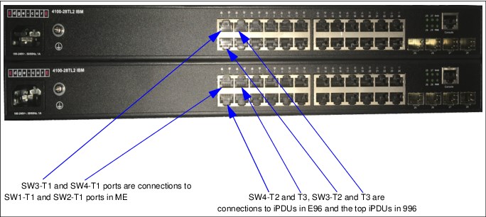
Figure 2-32 Twenty-four-port Ethernet switches (SW3 and SW4) at the bottom of DS8950F model 996 for extra iPDUs
|
Important: The internal Ethernet switches that are shown in Figure 2-31 and Figure 2-32 are for the DS8900F private networks only. Do not connect an external network (or any other equipment) to the black or gray network switches.
|
..................Content has been hidden....................
You can't read the all page of ebook, please click here login for view all page.