

IBM DS8900F reliability, availability, and serviceability
This chapter describes the reliability, availability, and serviceability (RAS) characteristics of the IBM DS8900F.
This chapter covers the following topics:
3.1 DS8900F processor complex features
RAS is an important concept in the design of the DS8900F. Hardware features, software features, design considerations, and operational guidelines all contribute to make the DS8900F reliable. At the heart of the DS8900F is a pair of POWER9 processor-based servers. These servers, which are known as central processor complexes (CPCs), share the load of receiving and moving data between the attached hosts and the storage arrays. For more information, see IBM Power Systems S922, S914, and S924 Technical Overview and Introduction, REDP-5497.
However, the CPCs are also redundant so that if either one fails, the system switches to the remaining CPC and continues to run without any host I/O interruption. This section looks at the RAS features of the CPCs, including the hardware, the operating system (OS), and the interconnections.
3.1.1 POWER9 PowerVM Hypervisor
The POWER9 IBM PowerVM® Hypervisor (PHYP) is a component of system firmware that is always active regardless of the system configuration, even when it is not connected to the Management Console (MC). PHYP runs on the flexible service processor (FSP). It requires the FSP processor and memory to support the resource assignments to the logical partition (LPAR) on the server. It operates as a hidden partition with no CPC processor resources that are assigned to it, but it does allocate a small amount of memory from the partition.
The PHYP provides the following capabilities:
•Reserved memory partitions set aside a portion of memory to use as cache and a portion to use as non-volatile storage (NVS) functioning as write cache.
•Preserved memory support allows the contents of the NVS and cache areas to be protected if a server restarts.
•I/O enclosure initialization, power control, and slot power control prevent a CPC that is restarting from initializing an I/O adapter that is in use by another server.
•It provides automatic restart of a hung or stopped partition. The PHYP also monitors the service processor and runs a reset or reload if it detects the loss of the service processor. It notifies the OS if the problem is not corrected.
The AIX OS uses PHYP services to manage the Translation Control Entry (TCE) tables. The OS communicates the wanted I/O bus address to logical mapping, and the PHYP returns the I/O bus address to physical mapping within the specific TCE table. The PHYP needs a dedicated memory region for the TCE tables to convert the I/O address to the partition memory address. The PHYP then can monitor direct memory access (DMA) transfers to the Peripheral Component Interconnect Express (PCIe) adapters.
3.1.2 POWER9 processor
The POWER9 processor implements 64-bit IBM Power Architecture® technology. The multi-core architecture of the POWER9 processor-based modules is matched with innovation across a wide range of related technologies to deliver leading throughput, efficiency, scalability, and RAS.
Areas of innovation, enhancement, and consolidation
The POWER9 processor represents an important performance increase that can be as high as 70% over previous comparable hardware generations. The POWER9 processor has the following areas of innovation, enhancement, and consolidation:
•A large on-chip, low-latency L3 cache that is implemented in embedded dynamic random access memory (eDRAM). Lower energy consumption and a smaller physical footprint are two of the benefits.
•Cache hierarchy and component innovation.
•Advances in memory subsystem with eight memory channels.
•Advances in off-chip signaling.
•The POWER9 processor has intelligent threads that can vary based on the workload demand. The system automatically selects whether a workload benefits from dedicating as much capability as possible to a single thread of work, or if the workload benefits more from spreading the capability across up to 44 threads (four per core) of work by using simultaneous multithreading (SMT). With more threads, the POWER9 processor can deliver more total capacity as more tasks are accomplished in parallel. With fewer threads, those workloads that need fast individual tasks can get the performance that they need for maximum benefit.
The remainder of this section describes the RAS features of the POWER9 processor. These features and abilities apply to the DS8900F. You can read more about the POWER9 and processor configuration from the DS8900F architecture point of view in 2.3.1, “IBM POWER9 processor-based CPCs” on page 42.
POWER9 RAS features
The following sections describe the RAS leadership features of IBM POWER9 processor-based systems.
POWER9 processor instruction retry and recovery (IRR)
As with previous generations, the POWER9 processor can run processor instruction retry and alternative processor recovery for many core-related faults. This ability reduces exposure to permanent and intermittent errors in the processor core.
With the instruction retry function, when an error is encountered in the core in caches and certain logic functions, the POWER9 processor first automatically retries the instruction. If the source of the error was truly transient, the instruction succeeds and the system can continue normal operation.
POWER9 cache protection and cache error handling
The processor instruction retry function protects processors and data caches. The L1 cache is divided into sets. The POWER9 processor can deallocate all but one set before a processor instruction retry is run. In addition, faults in the segment lookaside buffer (SLB) array are recoverable by the PHYP. The SLB is used in the core to run address translation calculations.
The L2 and L3 caches in the POWER9 processor are protected with double-bit detect single-bit correct error correction code (ECC). Single-bit errors are corrected before they are forwarded to the processor, and then they are written back to L2 or L3.
In addition, the caches maintain a cache line delete capability. A threshold of correctable errors that is detected on a cache line can result in purging the data in the cache line and removing the cache line from further operation without requiring a restart. An ECC uncorrectable error that is detected in the cache can also trigger a purge and delete of the cache line.
This action results in no loss of operation because an unmodified copy of the data can be held in system memory to reload the cache line from main memory. Modified data is handled through special uncorrectable error handling. L2 and L3 deleted cache lines are marked for persistent deconfiguration on subsequent system restarts until they can be replaced.
POWER9 first-failure data capture
First-failure data capture (FFDC) is an error isolation technique. FFDC ensures that when a fault is detected in a system through error checkers or other types of detection methods, the root cause of the fault is captured without the need to re-create the problem or run an extended tracing or diagnostics program.
For most faults, a good FFDC design means that the root cause is detected automatically without intervention by an IBM Systems Service Representative (IBM SSR). Pertinent error data that relates to the fault is captured and saved for analysis. In hardware, FFDC data is collected from the fault isolation registers and the associated logic. In firmware, this data consists of return codes, function calls, and other items.
FFDC check stations are carefully positioned within the server logic and data paths to ensure that potential errors can be identified quickly and accurately tracked to a field-replaceable unit (FRU).
This proactive diagnostic strategy is an improvement over the classic, less accurate restart and diagnose service approach.
Redundant components
High opportunity components (those components that most affect system availability) are protected with redundancy and the ability to be repaired concurrently.
The following redundant components allow the system to remain operational:
•POWER9 cores, which include redundant bits in L1 instruction and data caches, L2 caches, and L2 and L3 directories.
•IBM Power S922 and IBM Power S924 use CPC main memory with Direct Attach Industry Standard DIMMs (ISDIMMs), which use an ECC algorithm that improves single-bit error correction and memory failure identification.
•Redundant cooling.
•Redundant power supply units (PSUs).
•Redundant links to the I/O subsystem.
•Concurrent maintenance for PCI adapters.
Self-healing
For a system to be self-healing, it must be able to recover from a failing component by detecting and isolating the failed component. The system is then able to take the component offline, fix, or isolate it, and then reintroduce the fixed or replaced component into service without any application disruption. Self-healing technology includes the following examples:
•Chipkill, which is an enhancement that enables a system to sustain the failure of an entire DRAM chip. The system can continue indefinitely in this state with no performance degradation until the failed dual inline memory module (DIMM) can be replaced.
•Single-bit error correction by using ECC without reaching error thresholds for main, L2, and L3 cache memory.
•L2 and L3 cache line delete capability, which provides more self-healing.
•ECC extended to inter-chip connections on the fabric and processor bus.
•Dynamic processor deallocation.
Bus cyclic redundancy check and lane repair
ECC is used internally in various data paths as data is transmitted between units. High-speed data buses can be susceptible to the occasional multiple bit errors due to the nature of the bus design. A cyclic redundancy check (CRC) code is used to determine whether there are errors within an entire packet of data. If a bit error is recognized, the bus can retrain and retry the operation and continue. CRC checking is done for the memory bus, and in POWER9 CRC checking is now done for the processor fabric bus interfaces sending data between processors.
The memory bus between processors and the memory uses CRC with retry. The design also includes a spare data lane so that if a persistent single data error exists, the faulty bit can be “self-healed.” The POWER9 busses between processors also have a spare data lane that can be substituted for a failing one to “self-heal” the single bit errors.
Memory reliability, fault tolerance, and integrity
POWER9 uses ECC circuitry for system memory to correct single-bit memory failures. The ECC algorithm works on ISDIMM pairs on a rank basis. With this ECC code, the system can dynamically allow correction from an entire DRAM failure (Chipkill) correction by using x4 DRAMs. It can also correct an error even if another symbol (a byte, which is accessed by a 2-bit line pair) experiences a fault.
A rank of four ISDIMMs contains enough DRAMs to provide 64 bits of data at a time with enough check bits to correct the case of a single DRAM module after the bad DRAM is detected, and then correct an extra faulty bit.
The ability to correct an entire DRAM is what IBM traditionally called Chipkill correction. Correcting this kind of fault is essential in protecting against a memory outage and should be considered as a minimum error correction for any modern server design.
The POWER9 processors that are used in DS8900F are designed internally for ISDIMMs without an external buffer chip. The ECC checking is at the 64-bit level, so Chipkill protection is provided with x4 DIMMs plus some additional sub Chipkill level error checking after a Chipkill event.
The memory DIMMs also use hardware scrubbing and thresholding to determine when memory modules within each bank of memory must be used to replace modules that exceeded their threshold of error count. Hardware scrubbing is the process of reading the contents of the memory during idle time and checking and correcting any single-bit errors that accumulated by passing the data through the ECC logic. This function is a hardware function on the memory controller chip, and does not influence normal system memory performance.
The ability to use hardware accelerated scrubbing to refresh memory that might have experienced soft errors is a given. The memory bus interface is also important. The direct bus-attach memory that is used in the scale-out servers supports RAS features in that design, including register clock driver (RCD) parity error detection and retry.
Fault masking
If corrections and retries succeed and do not exceed threshold limits, the system remains operational with full resources, and no external administrative intervention is required.
Mutual surveillance
The service processor monitors the operation of the IBM POWER Hypervisor firmware during the boot process and monitors for loss of control during system operation. It also allows the POWER Hypervisor to monitor service processor activity. The service processor can take the correct action (including calling for service) when it detects that the POWER Hypervisor firmware lost control. The POWER Hypervisor can also request a service processor repair action if necessary.
3.1.3 Cross-cluster communication
In the DS8900F, the I/O enclosures are connected point-to-point, and each CPC uses a PCIe architecture. DS8900F uses the PCIe paths between the I/O enclosures to provide the cross-cluster (XC) communication between CPCs. This configuration means that no separate path is between the XC communications and I/O traffic, which simplifies the topology. During normal operations, the XC communication traffic uses a small portion of the overall available PCIe bandwidth (less than 1.7%), so XC communication traffic has a negligible effect on I/O performance.
Figure 3-1 shows the redundant PCIe fabric design for XC communication in the DS8900F and depicts the single-chip modules (SCMs) (SCM #0 and SCM#1) in each CPC. If the I/O enclosure that is used as the XC communication path fails, the system automatically uses an available alternative I/O enclosure for XC communication.

Figure 3-1 DS8900F XC communication through the PCIe fabric and I/O enclosures
3.1.4 Environmental monitoring
The environment (power, fans, and temperature) is monitored by the FSP. Environmental critical and non-critical conditions generate emergency power-off warning (EPOW) events. Critical events (for example, a complete input power loss) trigger the correct signals from the hardware to start an emergency shutdown to prevent data loss without OS or firmware involvement. Non-critical environmental events are logged and reported by using Event Scan.
The temperature is also monitored. If the ambient temperature rises above a preset operating range, the rotational speed of the cooling fans increases. Temperature monitoring also warns the Licensed Internal Code (LIC) of potential environmental problems. An orderly system shutdown, including a service call to IBM, occurs when the operating temperature exceeds a critical level.
Voltage monitoring provides a warning and an orderly system shutdown when the voltage is out of the operational specification range.
More monitoring support can be found by running the DS CLI showsu command and viewing the Added Energy Report (ER) Test Mode, ER Recorded, ER Power Usage, ER Inlet Temp, ER I/O Usage, and ER Data Usage fields, as shown in Example 3-1.
Example 3-1 The showsu command
dscli> showsu
Name -
desc Sand Shark
ID IBM.2107-75HAL90
Model 996
WWNN 5005076309FFEC62
config Undefined
pw state On
pw mode Remote Manual
reqpm Remote Manual
System Memory 512.0 GB
MTS IBM.5331-75HAL90
ER Test Mode Disabled
ER Recorded 2022-06-22T22:39:03+0200
ER Power Usage 1730
ER Inlet Temp 23.0
ER I/O Usage 83
ER Data Usage 458
3.1.5 Resource deconfiguration
If recoverable errors exceed threshold limits, resources can be unconfigured to keep the system operational. This ability allows deferred maintenance at a more convenient time. Dynamic deconfiguration of potentially failing components is nondisruptive, which allows the system to continue to run. Persistent deconfiguration occurs when a failed component is detected. It is then deactivated on a subsequent restart.
Dynamic deconfiguration functions include the following components:
•Processor
•L3 cache lines
•Partial L2 cache deconfiguration
•PCIe bus and slots
Persistent deconfiguration functions include the following components:
•Processor
•Memory
•Unconfigure or bypass failing I/O adapters
•L2 cache
After a hardware error is flagged by the service processor, the subsequent restart of the CPC starts extended diagnostic testing. If a processor or memory is marked for persistent deconfiguration, the boot process attempts to proceed to completion with the faulty device automatically unconfigured. Failing I/O adapters are unconfigured or bypassed during the boot process.
3.2 CPC failover and failback
To understand the process of CPC failover and failback, you must review the logical architecture of the DS8900F. For more information, see Chapter 4, “Virtualization concepts” on page 107.
3.2.1 Dual cluster operation and data protection
For processing host data, a basic premise of RAS is that the DS8000 system always tries to maintain two copies of write data while the data moves through the storage system. Two areas of the primary memory of the nodes are used for holding host data: cache memory and NVS.
For a DS8980F model 998 with 4.3 TB total system memory or a DS8950F system with a maximum configuration of 3.4 TB of total system memory, NVS is 128 GB. For IBM DS8910F model 993 and DS8910F model 994, all configurations use 1/16th of system memory except for the smallest systems with 192 GB of total system memory, which uses the minimum of
8 GB of NVS. NVS contains write data until the data is destaged from cache to the drives. NVS data is protected and kept by non-volatile dual inline memory module (NVDIMM) technology, where the data is moved from DRAM to a flash memory on the NVDIMM modules if the DS8900F experiences a complete loss of input AC power.
8 GB of NVS. NVS contains write data until the data is destaged from cache to the drives. NVS data is protected and kept by non-volatile dual inline memory module (NVDIMM) technology, where the data is moved from DRAM to a flash memory on the NVDIMM modules if the DS8900F experiences a complete loss of input AC power.
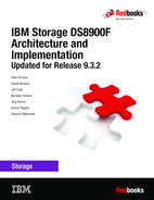
When a write is sent to a volume and both the nodes are operational, the write data is placed into the cache memory of the owning node and into the NVS of the other CPC. The NVS copy of the write data is accessed only if a write failure occurs and the cache memory is empty or possibly invalid. Otherwise, the NVS copy of the write data is discarded after the destaging from cache to the drives is complete.
The location of write data when both CPCs are operational is shown in Figure 3-2 on page 79, which shows how the cache memory of node 0 in CPC0 is used for all logical volumes that are members of the even logical subsystems (LSSs). Likewise, the cache memory of node 1 in CPC1 supports all logical volumes that are members of odd LSSs. For every write that is placed into cache, a copy is placed into the NVS memory that is in the alternative node. Therefore, the following normal flow of data for a write when both CPCs are operational is used:
1. Data is written to cache memory in the owning node. At the same time, data is written to the NVS memory of the alternative node.
2. The write operation is reported to the attached host as complete.
3. The write data is destaged from the cache memory to a drive array.
4. The write data is discarded from the NVS memory of the alternative node.
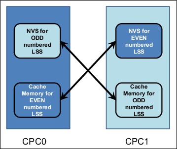
Figure 3-2 NVS write data when both CPCs are operational
Under normal operation, both DS8900F nodes are actively processing I/O requests. The following sections describe the failover and failback procedures that occur between the CPCs when an abnormal condition affects one of them.
3.2.2 Failover
In the example that is shown in Figure 3-3, CPC0 failed. CPC1 must take over all of the CPC0 functions. All storage arrays are accessible by both CPCs.
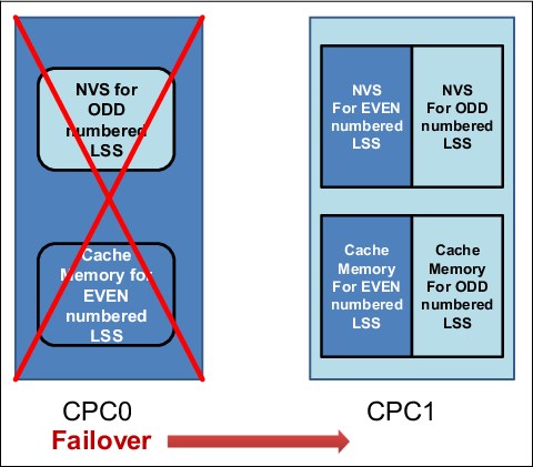
Figure 3-3 CPC0 failover to CPC1
At the moment of failure, node 1 in CPC1 includes a backup copy of the node 0 write data in its own NVS. From a data integrity perspective, the concern is the backup copy of the node 1 write data, which was in the NVS of node 0 in CPC0 when it failed. Because the DS8900F now has only one copy of that data (active in the cache memory of node 1 in CPC1), it performs the following steps:
1. Node 1 destages the contents of its NVS (the node 0 write data) to the drive subsystem. However, before the actual destage and at the beginning of the failover, the following tasks occur:
a. The surviving node starts by preserving the write data in cache that was backed up by the failed CPC NVS. If a restart of the single working CPC occurs before the cache data is destaged, the write data remains available for subsequent destaging.
b. The existing write data in cache (for which only a single volatile copy exists) is added to the NVS so that it remains available if the attempt to destage fails or a server restart occurs. This function is limited so that it cannot use more than 85% of NVS space.
2. The NVS and cache of node 1 are divided in two portions, one for the odd LSSs and one for the even LSSs.
3. Node 1 begins processing the I/O for all the LSSs, taking over for node 0.
This entire process is known as a failover. After failover, the DS8900F operates as shown in Figure 3-3 on page 79. Node 1 now owns all the LSSs, which means all reads and writes are serviced by node 1. The NVS inside node 1 is now used for both odd and even LSSs. The entire failover process is transparent to the attached hosts.
The DS8900F can continue to operate in this state indefinitely. No functions are lost, but the redundancy is lost, and performance is decreased because of the reduced system cache. Any critical failure in the working CPC renders the DS8900F unable to serve I/O for the arrays, so the IBM Support team begins work immediately to determine the scope of the failure and build an action plan to restore the failed CPC to an operational state.
3.2.3 Failback
The failback process begins automatically when the DS8900F determines that the failed CPC did not resume an operational state. If the failure was relatively minor and recoverable by the DS8900F OS, the software starts the resume action. If a service action occurred and hardware components were replaced, the IBM SSR or remote support engineer resumes the failed CPC.
This example in which CPC0 failed assumes that CPC0 was repaired and resumed. The failback begins with server 1 in CPC1 starting to use the NVS in node 0 in CPC0 again, and the ownership of the even LSSs being transferred back to node 0. Normal I/O processing, with both CPCs operational, then resumes. Just like the failover process, the failback process is transparent to the attached hosts.
In general, recovery actions (failover or failback) on the DS8900F do not affect I/O operation latency by more than 8 seconds.
If you require real-time response in this area, contact IBM to determine the latest information about how to manage your storage to meet your requirements.
3.2.4 NVS and power outages
DS8900F systems contain up to two pairs of intelligent power distribution units (iPDUs) in the base frame, and a third pair of iPDUs when a model E96 expansion frame is installed. One iPDU in each pair is in the green power domain, and its partner is in the yellow power domain.
During normal operation, the DS8900F preserves write data by storing a duplicate copy in the NVS of the alternative CPC. To ensure that write data is not lost during a power failure event, the DS8900F stores the NVS contents on non-volatile DIMMs (NVDIMMs). Each CPC contains two NVDIMMs with dedicated Backup Power Modules (BPMs). The NVDIMMs act as regular DRAM during normal operation. During AC power loss, the BPMs provide power to the NVDIMM modules until they have moved all modified data (NVS) to integrated flash memory. The NVDIMM save process is autonomous, and requires nothing from the CPC.
|
Important: DS8900F can tolerate a power line disturbance (PLD) for up to 20 ms. A PLD that exceeds 20 ms on both power domains initiates an emergency shutdown.
|
The following sections describe the steps that occur when AC input power is lost to both power domains.
Power loss
When a wall power loss condition occurs, the following events occur:
1. All host adapter I/O is blocked.
2. Each NVDIMM begins copying its NVS data to the internal flash partition.
3. The system powers off without waiting for the NVDIMM copy operation.
4. The copy process continues and completes independently from the storage systems power.
Power restored
When power is restored, the DS8900F must be powered on manually unless the remote power control mode is set to automatic.
|
Note: Be careful if you decide to set the remote power control mode to automatic. If the remote power control mode is set to automatic, after input power is restored, the DS8900F is powered on automatically.
|
After the DS8900F is powered on, the following events occur:
1. The CPCs are powered on, PHYP loads, and power-on self-test (POST) runs.
2. Each CPC boots up, and begins the initial microcode load (IML).
3. At an early stage in the IML process, the CPC detects NVS data on its NVDIMMs and restores the data to destage it to the storage drives.
3.3 Data flow in the DS8900F
The DS8900F connectivity between the CPC and the I/O enclosures uses the PCIe architecture. For more information, see 2.3.5, “Peripheral Component Interconnect Express adapters” on page 47.
3.3.1 I/O enclosures
As shown in Figure 3-1 on page 76, each CPC on a DS8950F is connected to two or four I/O enclosures in the base frame, and up to eight I/O enclosures when the expansion frame is installed. Each I/O enclosure functions as an extension the CPCs. The DS8910F model 993 has a maximum of two I/O enclosures. The DS8910F model 994 has base of two I/O enclosures and a maximum of four. The DS8980F Model 998 and DS8950F model 996 start with two I/O enclosures up to a maximum of eight.
The DS8900F I/O enclosures use adapters with PCIe connections. The adapters in the I/O enclosures are concurrently replaceable. Each slot can be independently powered off for installation, replacement, or removal of an adapter.
In addition, each I/O enclosure has N+1 power and cooling redundancy in the form of two PSUs with integrated fans, and two enclosure cooling fans. The PSUs and enclosure fans can be replaced concurrently without disruption to the I/O enclosure.
3.3.2 Host connections
Each DS8900F 32 Gbps or 16 Gbps Fibre Channel (FC) host adapter provides four longwave (LW) or shortwave (SW) ports for connectivity to storage area network (SAN) switches, or directly to hosts. Each port can be independently configured for FCP or FICON topology.
Single or multiple paths
The host adapters are shared between the CPCs. To illustrate this concept, Figure 3-4 on page 83 shows a potential system configuration. In this example, two I/O enclosures are shown. Each I/O enclosure has up to four FC host adapters. If a host server has only a single path to a DS8900F, as shown in Figure 3-4 on page 83, it can access volumes that belong to all LSSs because the host adapter directs the I/O to the correct CPC. However, if an error occurs on the host adapter, host adapter port, I/O enclosure, or in the SAN, all connectivity is lost because this configuration has no redundancy. The same is true for the host bus adapter (HBA) in the attached host, making it a single point of failure (SPoF) without a redundant HBA.
|
Important: For host connectivity, hosts that access the DS8900F must have at least two connections to I/O ports on separate host adapters in separate I/O enclosures.
|
Figure 3-4 shows a single-path host connection.

Figure 3-4 A single-path host connection
A more robust design is shown in Figure 3-5, in which the host is attached to separate FC host adapters in separate I/O enclosures. This configuration is also important because during a LIC update, a host adapter port might need to be taken offline. This configuration allows host I/O to survive a hardware failure on any component on either path.

Figure 3-5 A dual-path host connection
SAN and FICON switches
Because many hosts can connect to the DS8900F by using multiple paths, the number of host adapter ports that are available in the DS8900F might not be sufficient to accommodate all the connections. The solution to this problem is to use SAN switches or directors to switch logical connections from multiple hosts. In an IBM Z environment, a SAN switch or director that supports FICON is required.
A logic or power failure in a switch or director can interrupt communication between hosts and the DS8900F. Provide more than one switch or director to ensure continued availability. Configure ports from two separate host adapters in two separate I/O enclosures to go through each of two directors. The complete failure of either director leaves the paths that are configured to the alternative director still available.
Support for the T10 Data Integrity Field standard
The DS8900F incorporates the American National Standards Institute (ANSI) T10 Data Integrity Field (DIF) standard for Fixed-Block (FB) volumes.
When data is read, the DIF is checked before the data leaves the DS8900F and again when the data is received by the host system. Previously, it was possible to ensure the data integrity within the storage system only with ECC. However, T10 DIF can now check end-to-end data integrity through the SAN. Checking is done by hardware, so no performance impact occurs.
For more information about T10 DIF implementation in the DS8900F, see “T10 Data Integrity Field support” on page 118.
Robust and resilient SAN data transfer
Forward Error Correction (FEC) is enabled on 16 Gbps and 32 Gbps host adapters to intercept and correct bit errors for utmost reliability. FEC is also implemented on IBM z13 and later systems, providing end-to-end reliability.
To provide more proactive system diagnosis information about SAN fabric systems, the Read Diagnostic Parameters (RDP) function, which complies with industry standards, is implemented on the DS8900F. This function provides host software with the capability to perform predictive failure analysis (PFA) on degraded SAN links before they fail.
When troubleshooting SAN errors, the IBM SSR can run a wrap test on a single host adapter port without taking the entire adapter offline.
Multipathing software
Each attached host OS requires multipathing software to manage multiple paths to the same device, and to provide redundant routes for host I/O requests. When a failure occurs on one path to a logical device, the multipathing software on the attached host can identify the failed path and route the I/O requests for the logical device to alternative paths. Furthermore, it can likely detect when the path is restored. The multipathing software that is used varies by attached host OS and environment, as described in the following sections.
Open systems
In most open systems environments, multipathing is available at the OS level. The Subsystem Device Driver (SDD), which was provided and maintained by IBM for several OSs, is now an obsolete approach for a multipathing solution.
|
Important: The IBM System Storage Multipath Subsystem Device Driver is no longer supported for IBM DS8000. The Subsystem Device Driver Device Specific Module (SDDDSM) for Windows and Subsystem Device Driver Path Control Module (SDDPCM) for AIX are end of service (EOS). Clients must move to the native multipath OS software to get continuous support from IBM. For more information, see SDDDSM and SDDPCM End Of Support for DS8000.
|
For the AIX OS, the DS8000 is supported through the AIX multipath I/O (MPIO) framework, which is included in the base AIX OS. Use the base AIX Multipath I/O Path Control Module (AIXPCM) support instead of the old SDDPCM.
For multipathing under Microsoft Windows, the DS8000 is supported by the native Microsoft MPIO stack by using Microsoft Device Specific Module (MSDSM). Existing environments that rely on the old SDDDSM should be moved to the native OS driver.
|
Note: To move existing SDDPCM and SDDDSM implementations, see the following resources:
|
For all newer versions of RHEL and SUSE Linux Enterprise Server, the native Linux multipathing driver, Device-Mapper Multipath (DM Multipath), is used.
Also, on the VMware vSphere ESXi server, the VMware Native Multipathing Plug-in (NMP) is the supported multipathing solution.
For more information about the multipathing software that might be required for various OSs, see the IBM System Storage Interoperation Center (SSIC).
IBM Z
In the IBM Z environment, a best practice is to provide multiple paths from each host to a storage system. Typically, four or eight paths are configured. The channels in each host that can access each logical control unit (LCU) in the DS8900F are defined in the hardware configuration definition (HCD) or input/output configuration data set (IOCDS) for that host. Dynamic Path Selection (DPS) allows the channel subsystem to select any available (non-busy) path to start an operation to the disk subsystem. Dynamic Path Reconnect (DPR) allows the DS8900F to select any available path to a host to reconnect and resume a disconnected operation, for example, to transfer data after disconnection because of a cache miss.
These functions are part of the IBM z/Architecture®, and are managed by the channel subsystem on the host and the DS8900F.
A physical FICON path is established when the DS8900F port sees light on the fiber, for example, a cable is plugged in to a DS8900F host adapter, a processor or the DS8900F is powered on, or a path is configured online by z/OS. Logical paths are established through the port between the host, and part or all of the LCUs in the DS8900F are controlled by the HCD definition for that host. This configuration happens for each physical path between an IBM Z host and the DS8900F. Multiple system images can be in a CPU. Logical paths are established for each system image. The DS8900F then knows the paths that can be used to communicate between each LCU and each host.
Control-unit initiated reconfiguration (CUIR) varies off a path or paths to all IBM Z hosts to allow service to an I/O enclosure or host adapter, then varies on the paths to all host systems when the host adapter ports are available. This function automates channel path management in IBM Z environments in support of selected DS8900F service actions.
CUIR is available for the DS8900F when it operates in the z/OS and IBM z/VM® environments. CUIR provides automatic channel path vary on and vary off actions to minimize manual operator intervention during selected DS8900F service actions.
CUIR also allows the DS8900F to request that all attached system images set all paths that are required for a particular service action to the offline state. System images with the correct level of software support respond to such requests by varying off the affected paths, and either notifying the DS8900F system that the paths are offline, or that it cannot take the paths offline. CUIR reduces manual operator intervention and the possibility of human error during maintenance actions, and reduces the time that is required for the maintenance. This function is useful in environments in which many z/OS or z/VM systems are attached to a DS8900F.
3.3.3 Metadata checks
When application data enters the DS8900F system, special codes or metadata, also known as redundancy checks, are appended to that data. This metadata remains associated with the application data while it is transferred throughout the DS8900F. The metadata is checked by various internal components to validate the integrity of the data as the data moves throughout the disk system. It is also checked by the DS8900F before the data is sent to the host in response to a read I/O request. The metadata also contains information that is used as an extra level of verification to confirm that the data that is returned to the host is coming from the location that you want on the disk.
The metadata check is independent of the DS8900F T10 DIF support for FB volumes. For more information about T10 DIF implementation in the DS8000, see “T10 Data Integrity Field support” on page 118.
3.4 RAS on the Hardware Management Console
The Hardware Management Console (HMC) is used to configure, manage, and maintain the DS8900F. Two HMCs (the primary and the secondary) are included in every DS8900F Management Enclosure (ME) in the base frame. The DS8900F HMCs work with IPv4, IPv6, or a combination of both IP standards. For more information about the HMC and network connections, see 6.1.1, “Management Enclosure” on page 168 and 5.3, “Network connectivity planning” on page 159.
The HMC is the DS8900F management focal point. If no HMC is operational, it is impossible to run maintenance, modifications to the logical configuration, or Copy Services (CS) tasks, such as the establishment of FlashCopy backups, Metro Mirror (MM) or Global Mirror (GM), by using the DS Command-line Interface (DS CLI), Storage Management GUI, or IBM Copy Services Manager. The implementation of a secondary HMC provides a redundant management focal point and is especially important if CS or Encryption Key Manager (EKM) are used.
3.4.1 Licensed Internal Code updates
The DS8900F contains many discrete redundant components. The DS8900F architecture allows concurrent code updates. This ability is achieved by using the redundant design of the DS8900F. The following components have firmware that can be updated concurrently:
•FSP and IBM Power firmware
•iPDU
•Rack power control cards (RPCCs)
•Host adapters
•Flash enclosure
•Device adapters (DAs)
•Flash drives
•I/O enclosure
The DS8900F CPCs have an OS (AIX) and Licensed Machine Code (LMC) that can be updated. As IBM continues to develop and improve the DS8900F, new releases of firmware and LMC become available that offer improvements in function and reliability. For more information about LIC updates, see Chapter 11, “Licensed Machine Code” on page 405.
3.4.2 Call Home and remote support
This section describes the Call Home feature and remote support capability.
Call Home
Call Home is the capability of the DS8900F to notify the client and IBM Support to report a problem. Call Home is configured in the HMC at installation time. Call Home to IBM Support is done over the customer network through a secure protocol. Customer notifications can also be configured as email (SMTP) or Simple Network Management Protocol (SNMP) alerts. An example of an email notification output is shown in Example 3-2.
Example 3-2 Typical email notification output
REPORTING SF MTMS: 2107-996*75HAL90
FAILING SF MTMS: 5331-996*75HAL90
REPORTING SF LPAR: unknown
PROBLEM NUMBER: 270
PROBLEM TIMESTAMP: Oct 16, 2019 3:15:46 PM CEST
REFERENCE CODE: BE83CB93
************************* START OF NOTE LOG **************************
BASE RACK ORDERED MTMS 5331-996*75HAL90
LOCAL HMC MTMS 8100LI7*I336057 HMC ROLE Primary
LOCAL HMC OUTBOUND CONFIG SSL only FTP: enabled
REMOTE HMC MTMS 8100LI7*I336145 HMC ROLE Secondary
REMOTE HMC OUTBOUND CONFIG Internet only FTP: enabled
AOS STATUS Running AOS VERSION 4.0
AOS ACL=(DS8k, Storage) AOS TRACE Enable
RSC STATUS Running RSC PASSWORD Required
HMC CE default HMC REMOTE default
HMC PE default HMC DEVELOPER default
2107 BUNDLE 89.0.208.0
HMC BUILD 1909192353
HMC BUILD 1909192353
LMC LEVEL v25.90.0 build level 20191013.1
FIRMWARE LEVEL SRV0 01VL93087 SRV1 01VL93087
STORAGE FACILITY 2107-996*75HAL90,
PARTITION NAME SF75HAL90ESS11
PARTITION HOST NAME SF75HAL90ESS11
PARTITION STATUS SFI 2107-996*75HAL91 SVR 9009-42A*785A6C0 LPAR SF75HAL90ESS11 STATE = AVAILABLE
FIRST REPORTED TIME Oct 16, 2019 3:15:46 PM CEST
LAST REPORTED TIME Oct 16, 2019 3:15:46 PM CEST
CALL HOME RETRY #0 of 12 on Oct 16, 2019 3:15:47 PM CEST.
REFCODE BE83CB93..... <=== system reference code (SRC)
SERVICEABLE EVENT TEXT
Device adapter reset reached threshold, adapter fenced. ... <=== Description of Problem
FRU group MEDIUM FRU class FRU
FRU Part Number 01LT624 FRU CCIN DAQN
FRU Serial Number 0095G725
FRU Location Code U1500.1B2.RJAAL2Y-P1-C6
FRU Previously Replaced No
FRU Previous PMH N/A
************************** END OF NOTE LOG ***************************
For more information about planning the connections that are needed for HMC installations, see Chapter 6, “IBM DS8900F Management Console planning and setup” on page 167.
For more information about setting up SNMP notifications, see Chapter 12, “Monitoring and support” on page 423.
Remote support
Remote support provides the ability of IBM Support personnel to remotely access the DS8900F. This capability can be configured at the HMC, and access is through Assist On-site (AOS) or by IBM Remote Support Center (RSC).
For more information about remote support operations, see Chapter 12, “Monitoring and support” on page 423.
For more information about AOS, see IBM Assist On-site for Storage Overview, REDP-4889.
3.5 RAS on the storage system
The DS8900F was designed to safely store and retrieve large amounts of data. Redundant array of independent disks (RAID) is an industry-wide method to store data on multiple physical disks to enhance data redundancy. Many variants of RAID are used today. The DS8900F system supports RAID 6, RAID 10, and RAID 5 (by Request for Price Quotation (RPQ) only).
|
Note: Due to the added resiliency of RAID 6, RAID 5 is not recommended and only supported by RPQ.
|
3.5.1 RAID configurations
The following RAID configurations are supported on DS8900F:
•5+P+Q+S RAID 6 configuration: The array consists of five data drives and two parity drives. The remaining drive on the array site is used as a spare.
•6+P+Q RAID 6 configuration: The array consists of six data drives and two parity drives.
•3+3+2S RAID 10 configuration: The array consists of three data drives that are mirrored to three copy drives. Two drives on the array site are used as spares.
•4+4 RAID 10 configuration: The array consists of four data drives that are mirrored to four copy drives.
•6+P+S RAID 5 configuration (by RPQ only): The array consists of six data drives and one parity drive. The remaining drive of the array site is used as a spare.
•7+P RAID 5 configuration (by RPQ only): The array consists of seven data drives and one parity drive.
|
Note: The following characteristics refer to RAID:
•Spare drives are globally available to the flash RAID controller pair.
•The P and Q indicators do not mean that individual drives are dedicated to holding the parity bits for the array, but rather, they designate the equivalent capacity of the parity drives. By design, RAID 6 and RAID 5 both employ a rotating parity architecture so that no single drive is always involved in every write operation. The data and parity stripes are distributed among the member drives of the array to provide optimum write performance.
|
IBM Storage Modeler is an easy-to-use web tool that is available only to IBM personnel and Business Partners to help with capacity planning for physical and usable capacities that are based on installation drive capacities and quantities in intended RAID configurations.
RAID 6 is the default when creating new arrays by using the DS Storage Manager GUI.
|
Important: The following restrictions apply:
•A Request for Price Quotation (RPQ) / Storage Customer Opportunity Request (SCORE) is required to use RAID 5.
•Within one High-Performance Flash Enclosure (HPFE) Gen2 pair of six array sites, a RAID intermix is allowed, but no intermix of high-performance drives (Flash Tier 0) with high-capacity drives (Flash Tier 1 or Flash Tier 2) is supported.
For the latest information about supported RAID configurations and to request an RPQ / SCORE, contact your IBM SSR.
|
3.5.2 Drive path redundancy
Each flash drive inside an HPFE in the DS8900F is attached to two SAS switch expanders, which are contained within the Enclosure Service Modules (ESMs) in the flash drive enclosure. Figure 3-6 shows the redundancy features of the DS8900F switched SAS drive architecture.
Each flash drive has two separate connections to the enclosure backplane. This configuration allows a flash drive to be simultaneously attached to both SAS expander switches. If either ESM is removed from the enclosure, the SAS expander switch in the remaining ESM retains the ability to communicate with all the flash drives and both flash RAID controllers in the DA pair. Similarly, each DA has a path to each switch, so it can also tolerate the loss of a single path. If both paths from one DA fail, it cannot access the switches. However, the partner DA retains connectivity to all drives in the enclosure pair.

Figure 3-6 Flash Drive Enclosure Paths
For more information about the drive subsystem of the DS8900F, see 2.5, “Flash drive enclosures” on page 56.
3.5.3 Flash RAID controller redundancy
Flash RAID controllers are always installed in pairs and connect to a pair of HPFEs, which are also always installed in pairs. Each controller provides four ports that are connected across each of the four ESMs in the flash enclosures, for a total of eight paths.
The arrays are balanced between the flash enclosures to provide redundancy and performance. Both flash RAID controllers can access all arrays within the DA pair. Each controller in a DA pair is installed in different I/O enclosures, and each has allegiance to a different CPC.
Figure 3-7 on page 91 shows the connections for the DA and flash enclosure pair.

Figure 3-7 Dual paths on a flash drive enclosure
3.5.4 Predictive failure analysis
The flash drives that are used in the DS8900F incorporate PFA, and can anticipate certain forms of failures by keeping internal statistics of read/write errors. If the error rates exceed predetermined threshold values, the drive is nominated for replacement. Because the drive did not yet fail, data can be copied directly to a spare drive by using the technique that is described in 3.5.10, “Smart Rebuild” on page 95. This copy ability avoids using RAID recovery to reconstruct all the data on to the spare drive.
3.5.5 Disk scrubbing
The DS8900F periodically reads data on a flash drive. This reading is designed to occur without interfering with application performance. It is called background data scrubbing.
If ECC detects correctable bad bits, the bits are corrected immediately. This ability reduces the possibility of multiple bad bits accumulating in a block beyond the ability of ECC to correct them. If a block contains data that is beyond ECC’s ability to correct, RAID is used to regenerate the data and write a new copy onto a spare block or cell of the flash drive. This scrubbing process applies to flash drives that are array members and spares.
Data scrubbing can proactively relocate data, which reduces the probability of data reread impact. Data scrubbing does this relocation before errors add up to a level beyond error correction capabilities.
3.5.6 RAID support
Arrays can be configured as RAID 6, RAID 10, or RAID 5 (depending on the drive type).
|
Important: RAID 6 is now the default and preferred setting for the DS8900F. RAID 5 can be configured with exceptions, but it is not recommended and requires an RPQ. On high-capacity tiers (Tier 1 and Tier 2) RAID 5 is not allowed at all. RAID 10 continues to be an option for all-flash drive types.
|
The DS8900F uses the idea of rotating parity, which means that no single drive in an array is dedicated to holding parity data, which makes the drive active in every I/O operation. Instead, the drives in an array rotate between holding data stripes and holding parity stripes, balancing out the activity level of all drives in the array.
Spare drives
An HPFE Gen2 pair in a DS8900F can contain up to six array sites. Each array site contains eight flash drives, and the HPFE Gen2 pair has two spare flash drives for each enclosure pair. The first two array sites on a flash RAID controller (DA) pair have a spare that is assigned, and the rest of the array sites have no spare that is assigned if all flash drives are the same capacity. The number of required spare drives per flash enclosure pair applies to all available RAID levels.
3.5.7 RAID 6 overview
The DS8900F supports RAID 6 protection. RAID 6 presents an efficient method of data protection in double failure scenarios, such as two drive failures, two coincident media errors, or a hardware failure combined with a media error. RAID 6 protection provides greater fault tolerance than RAID 5 while consuming less raw drive capacity than RAID 10.
|
Note: RAID 6 is the default and preferred array configuration in DS8900F.
|
RAID 6 provides around a 1,000 times improvement over RAID 5 for impact risk. RAID 6 allows more fault tolerance by using a second independent distributed parity scheme (dual parity). Data is striped on a block level across a set of drives, similar to RAID 5 configurations. The second set of parity is calculated and written across all the drives, and allows reconstruction of the data even when two drives fail. The striping is shown in Figure 3-8.

Figure 3-8 Illustrating one RAID 6 stripe on a 5+P+Q+S array
RAID 6 is best used with large-capacity drives because they have a longer rebuild time. One risk is that longer rebuild times increase the possibility that a second drive error occurs during the rebuild window. Comparing RAID 6 to RAID 5 performance gives about the same results on reads.
For random writes, the throughput of a RAID 6 array is only two-thirds of a RAID 5 due to the extra parity handling. Workload planning is important before considering RAID 6 for write-intensive applications, including CS targets. In the case of high random-write ratios,
RAID 10 can be the better choice.
RAID 10 can be the better choice.
When RAID 6 is sized correctly for the I/O demand, it is a considerable reliability enhancement, as shown in Figure 3-8 on page 92.
RAID 6 implementation in the DS8900F
A RAID 6 array in one array site of a DS8900F can be built in one of the following configurations:
•In a seven-drive array, two drives are always used for parity, and the eighth drive of the array site is needed as a spare. This type of RAID 6 array is referred to as a 5+P+Q+S array, where P and Q stand for parity and S stands for spare.
•A RAID 6 array, which consists of eight drives, is built when all necessary spare drives are configured for the DA pair. An eight-drive RAID 6 array also always uses two drives for parity, so it is referred to as a 6+P+Q array.
Drive failure with RAID 6
When a drive fails in a RAID 6 array, the DA starts to reconstruct the data of the failing drive on to one of the available spare drives. An algorithm determines the location of the spare drive to use, depending on the capacity and the location of the failed drive. After the spare drive replaces a failed drive in a redundant array, the recalculation of the entire contents of the new drive is run by reading the corresponding data and parity in each stripe from the remaining drives in the array. This data is then written to the spare drive.
During the rebuilding of the data on the new drive, the DA can still handle I/O requests from the connected hosts to the affected array. Performance degradation might occur during the reconstruction because DAs and path resources are used to do the rebuild. Because of the dual-path architecture of the DS8900F, this effect is minimal. Additionally, any read requests for data on the failing drive require data to be read from the other drives in the array, and then the DA reconstructs the data.
Any subsequent failure during the reconstruction within the same array (second drive failure, second coincident medium errors, or a drive failure and a medium error) can be recovered without data loss.
Performance of the RAID 6 array returns to normal when the data reconstruction on the spare drive is complete. The rebuild time varies, depending on the capacity of the failed drive and the workload on the array and the DA. The completion time is comparable to a RAID 5 rebuild, but slower than rebuilding a RAID 10 array in a single drive failure.
3.5.8 RAID 10 overview
RAID 10 provides high availability (HA) by combining features of RAID 0 and RAID 1. RAID 0 optimizes performance by striping volume data across multiple drives. RAID 1 provides drive mirroring, which duplicates data between two drives. By combining the features of RAID 0 and RAID 1, RAID 10 provides more optimization for fault tolerance. Data is striped across half of the drives in the RAID 1 array. The same data is also striped across the other half of the array, which creates a mirror. Access to data is preserved if one drive in each mirrored pair remains available.
RAID 10 offers faster data reads and writes than RAID 6 or RAID 5 because it does not need to manage parity. However, with half of the drives in the group used for data and the other half mirroring that data, RAID 10 arrays have less usable capacity than RAID 6 or RAID 5 arrays.
RAID 10 is commonly used for workloads that require the highest performance from the drive subsystem. With RAID 6, each front-end random write I/O might theoretically lead to six back-end I/Os, including the parity updates (RAID penalty), but this number is four for
RAID 5 and only two for RAID 10 (not counting cache optimizations). A typical use case for RAID 10 is for workloads with a high random-write ratio. Either member in the mirrored pair can respond to the read requests.
RAID 5 and only two for RAID 10 (not counting cache optimizations). A typical use case for RAID 10 is for workloads with a high random-write ratio. Either member in the mirrored pair can respond to the read requests.
RAID 10 implementation in DS8900F
In the DS8900F, the RAID 10 implementation is achieved by using six or eight drives. If spares must be allocated from the array site, six drives are used to make a three-drive RAID 0 array, which is then mirrored to a three-drive array (3x3). If spares do not need to be allocated, eight drives are used to make a four-drive RAID 0 array, which is then mirrored to a four-drive array (4x4). For the required number of spares per flash drive enclosure pair, see “Spare drives” on page 92.
Drive failure with RAID 10
When a flash drive fails in a RAID 10 array, the DA rejects the failing drive and takes a hot spare into the array. Then, data is copied from the good drive to the hot spare drive. The spare that is used is chosen based on an algorithm that looks at the location of the spares and the size and location of the failed drive. Remember, a RAID 10 array is effectively a RAID 0 array that is mirrored. Therefore, when a drive fails in one of the RAID 0 arrays, you can rebuild the failed drive by reading the data from the equivalent drive in the other RAID 0 array.
While this data copy is occurring, the DA can still service read/write requests to the array from the hosts. Performance might degrade while the copy operation is in progress because DAs and path resources are used to rebuild the RAID 1 pair. Because a good drive is available, this effect is minimal. Read requests for data on the failed drive likely are not affected because they are all directed to the good copy on the mirrored drive. Write operations are not affected.
Performance of the RAID 10 array returns to normal when the data copy onto the spare drive completes. The time that is taken for rebuild can vary, depending on the capacity of the failed drive and the workload on the array and the DA.
Compared to RAID 5 or RAID 6, RAID 10 rebuild completion time is faster because rebuilding a RAID 5 or RAID 6 array requires several reads on the remaining stripe units plus one parity operation for each write. However, a RAID 10 configuration requires one read and one write (essentially, a direct copy).
3.5.9 RAID 5 implementation in DS8900F
RAID 5 is a method of spreading volume data plus parity data across multiple drives.
|
Important: RAID 5 can be configured for Tier 0 flash drives of less than 1 TB, but this configuration is not recommended, and requires a risk acceptance and an RPQ for high-performance flash drives. Tier 0 flash drive sizes larger than 1 TB (not Tier 1 and
Tier 2 high-capacity flash drives) can be configured by using RAID 5, but require an RPQ and an internal control switch to be enabled. |
An array site with a spare creates a RAID 5 array that is 6+P+S (where the P stands for parity and S stands for spare). The other array sites on the DA pair are 7+P arrays.
3.5.10 Smart Rebuild
Smart Rebuild is a function that is designed to help reduce the possibility of secondary failures and data loss of RAID arrays. It can be used to rebuild a RAID 6 array when certain drive errors occur and a normal determination is made that it is time to use a spare to proactively replace a failing flash drive. If the suspect drive is still available for I/O, it is kept in the array rather than being rejected as under a standard RAID rebuild. A spare is brought into the array, as an extra member, concurrently.
The suspect drive and the new member-spare are set up in a temporary RAID 1 association, allowing the troubled drive to be duplicated onto the spare rather than running a full RAID reconstruction (rebuild) from data and parity. The new member-spare is then made a regular member of the array and the suspect drive is rejected from the RAID array. The array never goes through an n-1 stage in which it might suffer a complete failure if another drive in this array encounters errors. The result saves substantial time and provides a new level of availability that is not available in other RAID products.
Smart Rebuild is not applicable in all situations, so it is not always used. Smart Rebuild runs only for healthy RAID arrays. If two drives with errors are in a RAID 6 configuration, or if the drive mechanism failed to the point that it cannot accept any I/O, the standard RAID rebuild procedure is used for the RAID array. If communications across a drive fabric are compromised, such as an SAS path link error that causes the drive to be bypassed, standard RAID rebuild procedures are used because the suspect drive is not available for a one-to-one copy with a spare. If Smart Rebuild is not possible or cannot complete, a standard RAID rebuild occurs.
Drive error patterns are continuously analyzed as part of the scheduled tasks that are run by the DS8900F LIC. Drive firmware is optimized to report predictive errors to the DA. At any time, when certain drive errors (following specific criteria) reach a specified threshold, the RAS LIC component starts Smart Rebuild within the hour. This enhanced technique, when it is combined with a more frequent schedule, leads to considerably faster identification of drives showing signs of imminent failure.
A fast response in fixing drive errors is vital to avoid multiple drive failures in an array, and to thus avoid potential data loss. The possibility of having an array with diminished redundancy, such as when a RAID rebuild occurs, is reduced by shortening the time when a specific error threshold is reached until Smart Rebuild is triggered, as described in the following scenarios:
•Smart Rebuild might avoid the circumstance in which a suspected drive is rejected because the Smart Rebuild process is started before rejection. Therefore, Smart Rebuild prevents the array from going to a standard RAID rebuild, during which the array has diminished redundancy.
•Because DS8900F LIC is continuously analyzing drive errors, any drive that exceeds the error threshold is detected immediately.
•The RAS LIC component starts Smart Rebuild after the Smart Rebuild threshold criteria are met. The Smart Rebuild analysis process runs every hour.
Smart Rebuild is also used to proactively rebalance member and spare drive distribution between the paths in a DA pair. Also, if a DA pair has a mix of different capacity flash drives, a larger spare may, in some cases, be taken by a smaller drive array. Smart Rebuild corrects this situation after the failing drives are replaced, and return the larger drive to the spare pool.
DS8000 Release 9.1 code provided an enhancement of the rebuild process by avoiding the rebuild of areas that are not mapped to logical volumes.
This process is performed by running a status command to the drives to determine whether the parity stripe is unmapped. This process prevents unnecessary writes (P/E cycles) of zeroed data to the target drive in a rebuild, allowing faster rebuild for partially allocated RAID arrays.
IBM SSRs and remote support can manually initiate a Smart Rebuild if needed, such as when two drives in an array are logging temporary media errors.
3.5.11 Spare creation
This section describes methods of spare creation.
Flash drive enclosures
When the arrays are created on a DS8900F flash drive enclosure, the LIC determines the array sites that contain spares. The first array sites on each flash RAID controller (DA) pair that are assigned to arrays contribute one or two spares (depending on the RAID option) until the DA pair has access to at least two spares, with spares initially placed on each enclosure in the pair.
A minimum of one spare is created for each array site that is assigned to an array until the following conditions are met:
•A minimum of two spares per DA pair exist.
•A minimum of two spares for the largest capacity array site on the DA pair exist.
Spare rebalancing
The DS8900F implements a spare rebalancing technique for spare drives. When a drive fails and a hot spare is taken, it becomes a member of that array. When the failed drive is repaired, DS8900F LIC might choose to allow the hot spare to remain where it was moved. However, it can instead choose to move the spare to a more optimum position. This migration is performed to better balance the spares across the two dual flash enclosure paths to provide the optimum spare location based on drive capacity and spare availability.
It might be preferable that the drive that is in use as an array member is converted to a spare. In this case, the data on that flash drive module is moved in the background onto an existing spare by using the Smart Rebuild technique. For more information, see 3.5.5, “Disk scrubbing” on page 91 and 3.5.10, “Smart Rebuild” on page 95. This process does not fail the disk that is being moved. However, the process reduces the number of available spares in the DS8900F until the migration process is complete.
In a flash drive intermix on a DA pair, it is possible to rebuild the contents of a smaller flash drive onto a larger spare drive. When the failed origin flash drive is replaced with a new drive, the DS8900F LIC moves the data back onto the recently replaced drive.
When this process completes, the smaller flash drive rejoins the array, and the larger drive becomes a spare again.
Hot-pluggable drives
Replacing a failed flash drive does not affect the operation of the DS8900F system because the drives are fully hot-pluggable. Each drive plugs into a SAS expander switch, so no path break is associated with the removal or replacement of a drive. In addition, no potentially disruptive loop initialization process occurs.
3.6 RAS on the power subsystem
This section describes the power subsystem components of the DS8900F from a RAS standpoint.
All power and cooling components that constitute the DS8900F power subsystem are fully redundant. The key element that allows this high level of redundancy is a dual power domain configuration that is formed of iPDU pairs. Dual PSUs in all major components provide a 2N redundancy for the system.
Combined with the NVDIMMs and the BPMs, which preserve the NVS write cache, the design protects the storage system in an input power failure.
The BPMs in each of the CPCs provide power to complete the movement of write data from cache memory to non-volatile flash storage if an input power loss occurs in both power domains (as described in 3.2.4, “NVS and power outages” on page 81).
The CPCs, I/O enclosures, and flash enclosures components in the frame all feature duplicated PSUs.
In addition, the ME includes redundant PSUs that provide dual power to the ME components, such as the primary and secondary HMCs, Rack Power Control (RPC) cards, and the internal Ethernet switches.
3.6.1 Power components
This section describes the following power components:
Intelligent Power Distribution Units
iPDUs are used to distribute power from the AC input power cords to all areas of the system. These areas include the PSUs in flash drive enclosures, CPCs, I/O enclosures, ME, and Ethernet switches.
iPDUs are installed in pairs, one in each input power domain. An iPDU module can be replaced concurrently, as described in 2.6.3, “Power domains” on page 64.
The iPDUs are firmware upgradeable and controlled and managed by the HMCs through its Ethernet interfaces.
For more information, see 2.6.2, “Intelligent Power Distribution Units” on page 59.
iPDUs support high or low voltage three-phase, and low-voltage single-phase input power. The correct power cables must be used. For more information about power cord Feature Codes, see IBM DS8900F Introduction and Planning Guide, GC27-9560.
Backup Power Modules and NVDIMMs
If AC input power is lost to both power domains, and is not restored within the 20 ms ride through time, an emergency shutdown is initiated, and the NVDIMMs copy the data from NVS to internal flash memory.
The BPMs provide the power for this emergency copy process of the NVDIMMs. They are firmware upgradeable. The condition of the BPMs is continually monitored by the CPC FSP. The BPMs have fast charge times that ensure that an empty BPM is charged and fully operational during the IML phase of the system when the storage system powers on so that no SPoF occurs. For more information, see 2.6.5, “Backup Power Modules and NVDIMM” on page 65.
The DS8900F BPMs have a 5-year lifetime. If a BPM must be replaced, the containing CPC must be set to service mode and shut down, which invokes a failover of all operations to the other CPC. Because of the high resilience of the system, the remaining CPC keeps the whole storage facility operable and in production servicing all I/Os. As a best practice, replacement should be done in a scheduled service window to avoid reduced performance and redundancy during peak workload hours. As the BPM is monitored, sufficient warning is given to schedule the service action.
Flash drive enclosure power supply units
The flash drive enclosure PSUs provide power for the drives, and they house the cooling fans for the drive enclosure. The fans draw air from the front of the frame, through the drives, and then out through the back of the frame. The entire frame cools from front to back, complying with the data center hot aisle / cold aisle cooling strategy. Redundant fans are in each PSU, and redundant PSUs are in each drive enclosure. The drive enclosure power supply can be replaced concurrently.
Each flash drive enclosure power supply plugs into two separate iPDUs, which must each be supplied by redundant independent customer power feeds.
CPC power supply units and I/O enclosure power supply units
Each CPC and I/O enclosure has dual redundant PSUs that each receive power from a designated iPDU pair. Each I/O enclosure and each CPC has its own cooling fans.
Rack power control cards
RPC cards monitor hardware conditions and provide control paths to the I/O enclosures and system LED indicators. Two RPCs are included for redundancy, and they are housed in the ME. When one RPC is unavailable, the remaining RPC performs all necessary functions. Section 2.6.1, “Rack power control cards” on page 58 explains the architectural implementation of the RPCs.
The following RPCC features are available:
•In DS8900F, all power control functions are managed by the HMCs.
•Two different buses are used for communication between each RPC and each CPC. These buses normally perform different functions, but also can maintain communication if one of the paths is failing.
•Each RPC has two firmware images. If an RPC firmware update fails, the RPC can still boot from the other firmware image. This design also provides firmware preload capability to reduce the duration of RPC firmware updates. During a firmware update, an RPC is unavailable only for the time that is required to boot from the new firmware image.
•The RPCs monitor power to the attached I/O enclosures. They also monitor environmental components, such as power, fans, and temperature for the I/O enclosures. Environmental critical and noncritical conditions can generate EPOW events. Critical events trigger the correct signals from the hardware to the affected components to prevent any data loss without OS or firmware involvement. Non-critical environmental events are also logged and reported.
3.6.2 Line power loss
The DS8900F uses an area of server memory as NVS. This area of memory is used to hold modified data that is not yet written to the storage drives. If power is lost to both input power domains, the DS8900F uses NVDIMMs to preserve that data. For a full explanation of the NVS and cache operation, see 3.2, “CPC failover and failback” on page 78.
3.6.3 Line power fluctuation
If a power fluctuation occurs that causes a momentary interruption to power (often called a brownout), the DS8900F tolerates this condition for approximately 20 ms. If this period is exceeded, the flash enclosure, CPC, and other components are powered off. Independently, the NVDIMMs remain powered by the BPMs, and begin copying the contents of NVS to the flash memory to hold the data for destage when the system becomes operational. For many clients who use uninterruptible power supply (UPS) technology, brownouts are not an issue. UPS-regulated power is reliable, so more redundancy in the attached devices is often unnecessary.
3.6.4 Power control
Power control functions are performed by the HMCs, which communicate sequencing information to the service processor in each CPC, RPC, and iPDU. Power control of the DS8900F can be performed by using the Service Maintenance Console Web User Interface (WUI) or by using the DS8900F Storage Management GUI or DS CLI commands.
Figure 3-9 shows the Power Control in the Actions menu on the dashboard of the Storage Management GUI.

Figure 3-9 DS8900F power control in the Storage Management GUI
Figure 3-10 shows the power control settings window of the Storage Management GUI.

Figure 3-10 DS8900F modify power control settings from the Storage Management GUI
In addition, the following switches in the ME of a DS8900F are accessible when the ME cover is open:
•The local mode jumper connector on the local remote switch card is for service use only. There is a plug to set the system to local (ME) power control mode.
•The local power on / local force power off switch (white switch) is also on the local remote switch card in the ME. This switch can manually power on or force power off the complete system if the local remote switch card is in local power control mode. When the local / remote switch card is in remote power control mode (nothing plugged in the local mode jumper connector), the HMCs are in control of power-on / power-off (this condition is the default for client usage).
•Powering off the storage system with the white switch is a forceful shutdown. It includes the procedure of moving NVS data to the flash portion of the NVDIMMs, which must be destaged on the next system power-on and start.
|
Important: The local / remote power off switch (white switch) must be used only by service personnel. The switch can be used only under certain circumstances and as part of an action plan or problem determination that is performed by an IBM SSR.
|
3.7 Other features
Many more features of the DS8900F enhance RAS. Several of these features are described in this section.
3.7.1 Internal network
Each DS8900F base frame contains two gigabit Ethernet (GbE) switches supporting a fully redundant pair of private management networks. Each CPC in the DS8900F has a connection to each switch. Each HMC has a connection to each switch. This configuration means that if a single Ethernet switch fails, all communication from the HMCs to other components in the storage system continue to function by using the alternative private network. If a model E96 is added to the DS8980F or DS8950F, two extra Ethernet switches are added to the base frame to provide internal private network connections to the expansion frame iPDUs. Section 6.1.3, “Private and Management Ethernet networks” on page 171 explains the design of the internal network in more detail.
|
Note: The Ethernet switches that are used internally in DS8900F are for private network communication only. No external connection to the private networks is allowed. Client connectivity to the DS8900F is allowed only through the provided external customer HMC Ethernet connectors (eth2 and eth1) at the rear of the base frame.
|
3.7.2 Earthquake resistance
The Earthquake Resistance Kit is an optional seismic kit for stabilizing the storage system frame so that the frame complies with IBM earthquake resistance standards. It helps to prevent personal injury and increases the probability that the system is available following an earthquake by limiting potential damage to critical system components.
Storage system frames with this optional seismic kit include hardware at the bottom of the frame that secures it to the floor. Depending on the flooring in your environment (specifically, non-raised floors), installation of the required floor mounting hardware might be disruptive. This kit must be special-ordered for the DS8900F. The kit is not available for the rack-mountable DS8910F model 993. For more information, contact your IBM SSR.
3.7.3 IBM Certified Secure Data Overwrite
IBM Certified Secure Data Overwrite (SDO) is a process that provides a secure erasure of all data in a DS8900F storage system. Before you perform a secure data erasure, you must remove all logical configuration. Encryption groups, if configured, must also be disbanded. Then, the process is initiated by the IBM SSR. The process continues unattended until it completes. This process can take a full day to complete.
The storage system also overwrites the areas that are usually not accessible and used only internally by the disk.
As illustrated in Figure 3-11, the data becomes unintelligible after this process.
Figure 3-11 Secure Data Erasure data workflow
Flash drives secure erasure
For flash-based drives or media, a combination of crypto-erase is run by zeroing any stored key information within flash drives, resetting the flash tables in RAM, and issuing a block erase to every flash block on the drive (format operation).
CPC and HMC
CPC drives are cleared through a single-pass overwrite, which is in accordance with National Institute of Standards and Technology (NIST) SP 800-88 Rev. 1. The HMC disk drives are also overwritten with a single pass. There is no customer data on the HMC drives because this process clears all diagnostics and support trace information.
NVDIMM
The NVDIMMs are cleared by applying a single-pass overwrite in accordance with NIST SP-800-881. This process is run in parallel on both CPCs.
Process overview
The SDO process is summarized in these steps:
1. After the logical configuration is removed, SDO is started from the primary HMC.
2. The primary HMC performs a dual cluster restart.
3. The crypto-erase and format of the flash drives is started.
4. The overwrite of the CPC hard disk drives (HDDs) are started in parallel (with each other and with the above).
5. The overwrite of the secondary HMC is started in parallel.
6. Both CPCs are restarted and the NVDIMMs are cleared.
7. After the overwrite of the CPC and secondary HMC HDDs is complete, the primary HMC HDD is overwritten.
8. The certificate is generated.
Certificate
The certificate provides written verification, by drive or flash drive serial number, of the full result of the overwrite operations. You can retrieve the certificate by using DS CLI, or your
IBM SSR can offload the certificate to removable media and provide it to you. Example 3-3 shows a sample SDO certificate.
IBM SSR can offload the certificate to removable media and provide it to you. Example 3-3 shows a sample SDO certificate.
Example 3-3 SDO sample certificate
Copyright (C) 2008, 2020 by International Business Machines Corporation
All Rights Reserved
Secure Data Overwrite Service for the IBM System Storage DS8900F
Certificate of Completion
IBM Corporation hereby confirms that:
1. IBM and the Customer entered into an agreement under which the Customer
retained IBM to provide Secure Data Overwrite Service for the below mentioned system
2. IBM performed such Secure Data Overwrite Service as set forth herein
3. IBM provided the Customer with a report, a copy of which is
attached to this certificate to identify the specific drives and
the level of Secure Data Overwrite Services applied on each drive.
Machine Type, Model Serial #: 5331-996*75NHxxx
System Serial #: 75NHxxx
Customer Data Drive Overwrite Option:
Single-pass Cryptographic Erase followed by a Sanitize Block Erase
Date of Service Completion: Mar 10, 2021
In all cases, the successful complexion of all erasure commands is a prerequisite for successful erasure.
Flash module (shown as 2.5" FLASH-FDE) were PURGED in accordance with NIST SP-800-88R1 for flash-based media, by issuing the sanitize command, which performs a crypto erase followed by block overwrite.
NVDIMMÕs NAND Flash blocks were CLEARED in accordance with NIST SP-800-88R1 for flash-based media, by applying a single overwrite pattern of 0x00. After the blocks are cleared, the data was read back to verify that the contents are erased. The overwrite and verification was performed by using vendor provided tools/methods.
CPC drives were CLEARED in accordance with NIST SP-800-88R1 for magnetic disks, by applying a single pass overwrite pattern of 0x00. Random samples, the first two sectors, and the last 10000 sectors were read back and verified to match the data written.
HMC flash base media drives were NOT securely erased. This device does not contain customer data, but the partition containing all trace data and diagnostic dumps was overwritten with single pass overwrite pattern of 0x00.
Scope
==================
This report covers the secure data overwrite service that is performed on the
DS8900F storage system with the serial number 75NH430
Drive Types Table
===========================
--------------------------------------------------------------------------------------
Drive Type | Drive Block | Drive | Number of | Number of
2.5" FLASH-FDE | Type | Capacity | drives | drives available for
| 528 | (GB) | installed | secure overwrite process
--------------------------------------------------------------------------------------
2.5" FLASH FDE |528 |400 | 16 | 16
--------------------------------------------------------------------------------------
The Drive Types Table provides information about each drive type that is installed on the DS8000 system.
a) Drive Type: This identifies that the drive is solid-state class of full disk encryption drive that is, 2.5" FLASH-FDE.
b) Drive block type: This identifies that the drive block consists of 528 bytes.
c) Drive Capacity: This identifies the specified drive type's capacity in GB.
d) Number of drives installed: This identifies the number of drives that are installed of a given drive type and capacity.
e) Number of drives available for secure overwrite process: This identifies the number of drives of a given drive type and capacity that is available for secure data overwrite.
Customer Data Drive Overwrite Results
=====================================
This section covers the devices that are used to store customer data (and associated metadata) both of which are subject to erasure.
Disk Type - All these devices are flash memory-based and are labeled as FLASH-FDE
Disk Serial# - Manufacturer assigned serial number visible on the device case
WWNN. - Device WWNN
Drive Location - Rack, Enclosure, and slot where the device is installed.
Overwrite Status - The success or failure of the overwrite operation
Sector Defect Count - Always zero for these devices.
Customer Data Drive Table
-------------------------
----------------------------------------------------------------------------------------------------------
|Disk Type | Disk Serial# | WWNN | Drive Location | Overwrite Status |Sector Defect Count|
----------------------------------------------------------------------------------------------------------
|2.5" FLASH-FDE |ZAJ1304E |5000C50030172544 |R1-F08-D8 |Successful |0 |
|2.5" FLASH-FDE |ZAJ131SE |5000C5003017349C |R1-F08-D7 |Successful |0 |
|2.5" FLASH-FDE |ZAJ131ZE |5000C50030173AB8 |R1-F08-D6 |Successful |0 |
|2.5" FLASH-FDE |ZAJ13243 |5000C500301736D8 |R1-F08-D5 |Successful |0 |
|2.5" FLASH-FDE |ZAJ132AT |5000C50030173A58 |R1-F08-D3 |Successful |0 |
|2.5" FLASH-FDE |ZAJ132L2 |5000C5003017383C |R1-F08-D4 |Successful |0 |
|2.5" FLASH-FDE |ZAJ132GW |5000C500301735B4 |R1-F08-D2 |Successful |0 |
|2.5" FLASH-FDE |ZAJ132AQ |5000C50030173648 |R1-F08-D1 |Successful |0 |
|2.5" FLASH-FDE |ZAJ15HE5 |5000C500302283B4 |R1-F07-D8 |Successful |0 |
|2.5" FLASH-FDE |ZAJ15HWY |5000C5003022817C |R1-F07-D7 |Successful |0 |
|2.5" FLASH-FDE |ZAJ15HPK |5000C500302281E0 |R1-F07-D6 |Successful |0 |
|2.5" FLASH-FDE |ZAJ15KM0 |5000C5003023CB00 |R1-F07-D5 |Successful |0 |
|2.5" FLASH-FDE |ZAJ15HT5 |5000C5003022849C |R1-F07-D2 |Successful |0 |
|2.5" FLASH-FDE |ZAJ15GWJ |5000C50030228068 |R1-F07-D1 |Successful |0 |
|2.5" FLASH-FDE |ZAJ15L1R |5000C5003023CBB8 |R1-F07-D3 |Successful |0 |
|2.5" FLASH-FDE |ZAJ15KJD |5000C5003023CAE0 |R1-F07-D4 |Successful |0 |
----------------------------------------------------------------------------------------------------------
CPC Drive Override Results
==========================
This section covers the devices on the processors that are used to store the operating system,
configuration data and trace data on the Central Processor Complex (CPC) servers.
Processor Complex # - This indicates the CPC in the DS8900F cluster
Hdisk Number - The operating system assigned identifier
CPC Drive Serial Number - Manufacturer assigned serial number visible on the device case
Overwrite Status - The success or failure of the overwrite operation
Completion Date - Completion timestamp
CPC Drive Table
---------------
--------------------------------------------------------------------------------
| Processor | hdisk | CPC Drive | Overwrite | Completion |
| Complex # | Number | Serial Number | Status | Date |
--------------------------------------------------------------------------------
| CPC 0 | hdisk0 | WAE1045Q | Successful | 2021/03/09 19:11:46 |
| CPC 0 | hdisk1 | WAE10N39 | Successful | 2021/03/09 20:10:31 |
| CPC 1 | hdisk0 | 0TJ5SJLP | Successful | 2021/03/09 19:13:16 |
| CPC 1 | hdisk1 | WAE104DZ | Successful | 2021/03/09 20:12:32 |
--------------------------------------------------------------------------------
Hardware Management Console (HMC) Drives
========================================
This section covers the devices on the processors that are used to store the operating system,
configuration data and trace data on the Hardware Management Console (HMC).
As noted above, these devices were NOT erased and only the partition containing logs
and dumps were deleted.
HMC Type - Indicates whether this is the first or optional second HMC
HMC Drive Serial Number - Manufacturer assigned serial number visible on the device case
Overwrite Status - The success or failure of the overwrite operation
Completion Date - Completion timestamp
HMC Drive Type - Always SSD for these systems
Hardware Management Console (HMC) Override Results
==================================================
--------------------------------------------------------------------------------------------------------
| HMC Type | HMC Drive Serial Number | SDO Results | Completion Date | HMC Drive Type |
| | | | | Hard Disk Drive/ |
| | | | | SSD |
--------------------------------------------------------------------------------------------------------
| First Management | N/A | Successful | 03/10/21-06:33:51 | SSD |
| Console | | | | |
--------------------------------------------------------------------------------------------------------
|Secondary Management| N/A | Successful | 03/10/21-03:49:39 | SSD |
| Console | | | | |
--------------------------------------------------------------------------------------------------------
Non-Volatile Dual In-Line Memory Module (NVDIMM)
================================================
This section covers the devices that are used to store customer data when system goes through emergency power off and the device is subject to erasure.
NVDIMM Location Code - Central Processor Complex (CPC) and slot where the device is
installed
Serial Number - Manufacturer assigned serial number visible on the device
NVDIMM Capacity - Device capacity in GB
Overwrite Status - The success or failure of the overwrite operation
Completion Date - Completion timestamp
NVDIMM Secure Erase Results
===========================
=========================================================================================
| NVDIMM Location Code | Serial Number | NVDIMM | Overwrite | Completion |
| | | Capacity | Status | Date |
=========================================================================================
| U78D2.001.WZS03ED-P1-C22 | YH10DP98G0E7 | 32 GB | Successful | 03/09/21 19:42:56 |
| U78D2.001.WZS03ED-P1-C36 | YH10DP98G0EX | 32 GB | Successful | 03/09/21 19:42:56 |
=========================================================================================
=========================================================================================
| U78D2.001.WZS03RG-P1-C22 | YH30DP944055 | 32 GB | Successful | 03/09/21 19:42:58 |
| U78D2.001.WZS03RG-P1-C36 | YH30DP94400R | 32 GB | Successful | 03/09/21 19:42:58 |
=========================================================================================
..................Content has been hidden....................
You can't read the all page of ebook, please click here login for view all page.