

IBM DS8900F physical planning and installation
This chapter describes the various steps that are involved in the planning and installation of the IBM DS8900F. It includes a reference listing of the information that is required for the setup and where to find detailed technical reference material.
This chapter covers the following topics:
For more information about the configuration and installation process, see the IBM DS8900F Introduction and Planning Guide, SC27-9560.
5.1 Considerations before the installation: Planning for growth
Start by developing and following a project plan to address the necessary topics for a successful implementation. Consider the following items for your installation plan checklist:
•Plan for growth to minimize disruption to operations.
|
Important: The IBM DS8980F and DS8950F systems support an expansion frame that can be installed adjacent or 20 meters away from the base frame. (Feature Code 1341 is needed.)
|
•Consider location suitability, floor loading, access constraints, elevators, and doorways.
•Analyze power requirements, such as redundancy and using an uninterruptible power supply (UPS).
•Examine environmental requirements, such as adequate cooling capacity.
•Full Disk Encryption (FDE) drives are a standard feature for the DS8900F. If encryption activation is required, consider the location and connection needs for the external key servers, such as IBM Security Key Lifecycle Manager or Gemalto SafeNet KeySecure servers.
•Consider the integration of Lightweight Directory Access Protocol (LDAP) to allow a single user ID and password management. LDAP can be configured from the Storage Management GUI, as described in 6.5.2, “Remote authentication” on page 188.
•Call Home through a Secure Sockets Layer (SSL) installation to provide a continued secure connection to the IBM Support center.
•Consider connecting to IBM Storage Insights that can help you predict and prevent storage problems before they impact your business.
•Plan for logical configuration, Copy Services (CS), and staff education. For more information, see Chapter 8, “Configuration flow” on page 225.
5.1.1 Client responsibilities for the installation
The DS8900F is specified as an IBM or IBM Business Partner installation and setup system. However, the following activities are several required planning and installation activities for which the client is responsible at a high level:
•Physical configuration planning
Your Storage Marketing Specialist can help you plan and select the DS8900F model physical configuration and features.
•Installation planning
•Integration of LDAP
IBM can help in planning and implementation at the client’s request.
•Installation of Assist On-site (AOS)
IBM can help plan and implement at the client’s request.
•Integration of IBM Spectrum Control and Simple Network Management Protocol (SNMP) into the client environment for monitoring of performance and configuration
IBM can provide services to set up and integrate these components.
•Configuration and integration of external key servers and IBM DS8000 Encryption for enhanced data security
Supported key servers for data at rest and Transparent Cloud Tiering (TCT) Encryption include IBM Security Key Lifecycle Manager, Gemalto Safenet KeySecure, and Thales Vormetric DSM. IBM Security Guardium Key Lifecycle Manager is the only supported key server for encryption of data in flight (IBM Fibre Channel Endpoint Security).
IBM provides services to set up and integrate IBM Security Guardium Key Lifecycle Manager components.
Alternatively, clients can install the Gemalto SafeNet key servers or Thales Vormetric DSM. For IBM Fibre Channel Endpoint Security, IBM Security Guardium Key Lifecycle Manager with Key Management Interoperability Protocol (KMIP) in Multi-Master mode is required.
•Logical configuration planning and application
Logical configuration refers to the creation of redundant array of independent disks (RAID) arrays and pools, and to the assignment of the configured capacity to servers. Application of the initial logical configuration and all subsequent modifications to the logical configuration also are client responsibilities. The logical configuration can be created, applied, and modified by using the DS GUI, DS Command-line Interface (DS CLI), or DS Open application programming interface (DS Open API).
IBM Services® also can apply or modify your logical configuration, which is a fee-based service.
5.1.2 Participants
A project manager must coordinate the many tasks that are necessary for a successful installation. Installation requires close cooperation with the user community, IT support staff, and technical resources that are responsible for floor space, power, and cooling.
A storage administrator must also coordinate requirements from the user applications and systems to build a storage plan for the installation. This plan is needed to configure the storage after the initial hardware installation is complete.
The following people must be briefed and engaged in the planning process for the physical installation:
•Systems and storage administrators
•Installation planning engineer
•Building engineer for floor loading, air conditioning, and electrical considerations
•Security engineers for AOS, LDAP, key servers, and encryption
•Administrator and operator for monitoring and handling considerations
•IBM Systems Service Representative (IBM SSR) or IBM Business Partner
5.1.3 Required information
A validation list to help the installation process must include the following items:
•Drawings that detail the DS8000 placement as specified and agreed upon with a building engineer, which ensures that the weight is within limits for the route to the final installation position.
•Approval to use elevators if the DS8900F weight and size are acceptable.
•Connectivity information, servers, storage area network (SAN), and mandatory local area network (LAN) connections.
•Agreement on the security structure of the installed DS8000 with all security engineers.
•Agreement on the detailed storage plan. Ensure that the configuration specialist has all of the information to configure all of the storage and set up the environment, as required.
•Activation codes for Base Functions (BFs), which are mandatory, and any optional feature activation codes.
5.2 Planning for the physical installation
This section describes the physical installation planning process and provides important tips and considerations.
5.2.1 Delivery and staging area
The shipping carrier is responsible for delivering and unloading the DS8900F as close to its final destination as possible. Inform the carrier of the weight and size of the packages to deliver. Also, inspect the site and the areas through which the packages will be moved (for example, hallways, floor protection, elevator size, and loading).
Table 5-1 lists the final packaged dimensions and maximum packaged weight of the DS8900F storage unit ship group. The maximum packaged weight is the maximum weight of the frame plus the packaging weight.
Table 5-1 Packaged dimensions and weight for DS8900F models
|
Shipping container
|
Packaged dimensions (in centimeters and inches)
|
Maximum packaged weight (in kilograms and pounds)
|
|
IBM DS8910F model 993
|
Height 1.49 m (58.7 in.)
Width 1.05 m (41.3 in.)
Depth 1.30 m (51.2 in.)
|
295 kg (650 lb)
|
|
DS8910F model 994
|
Height 2.22 m (87.7 in.)
Width 0.95 m (37.4 in.)
Depth 1.50 m (59.1 in.)
|
762 kg (1680 lb)
|
|
DS8950F model 996 and DS8980F model 998
|
Height 2.22 m (87.7 in.)
Width 1.0 m (39.4 in.)
Depth 1.50 m (59.1 in.)
|
793 kg (1748 lb)
|
|
Expansion Frame model E96
|
Height 2.22 m (87.7 in.)
Width 1.0 m (39.4 in.)
Depth 1.50 m (59.1 in.)
|
603 kg (1330 lb)
|
By using the shipping weight reduction option, you can receive delivery of a DS8900F model in multiple shipments that do not exceed 909 kg (2,000 lb) each.
The DS8910F model 993 can be integrated into an existing IBM z15 model T02, IBM LinuxONE Rockhopper III Model LT2, IBM z14 Model ZR1, IBM LinuxONE Rockhopper II Model LR1, or other standard 19-inch wide frame with 16U contiguous space. For more information, see IBM DS8910F Model 993 Rack-Mounted Storage System Release 9.1, REDP-5566.
For more information about the Shipping Weight Reduction option, see Chapter 7, “IBM DS8900F features and licensed functions” on page 199.
5.2.2 Floor type and loading
The DS8900F can be installed on a raised or nonraised floor. The total weight and space requirements of the storage unit depend on the configuration features that you ordered. You might consider calculating the weight of the unit and the expansion frame (if ordered) in their maximum capacity to allow for the addition of new features.
For the maximum weight of the various DS8900F models, see Table 5-1 on page 144.
|
Important: You must check with the building engineer or other appropriate personnel to ensure that the floor loading is correctly considered.
|
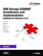
Figure 5-1 shows the location of the cable cutouts for DS8900F. You can use the following measurements when you cut the floor tile:
•Width: 41.91 cm (16.5 in.)
•Depth: 8.89 cm (3.5 in.)
•End of frame to edge of cable cutout: 10.0 cm (3.9 in.)

Figure 5-1 Floor tile cable cutout for DS8900F
For more information about floor loading and weight distribution, see IBM DS8900F Introduction and Planning Guide, SC27-9560.
5.2.3 Overhead cabling features
The overhead cabling (top exit) feature, as shown in Figure 5-2, is available for DS8900F as an alternative to the standard rear cable exit. Verify whether you ordered the top exit feature before the tiles for a raised floor are cut.
This feature requires the following items:
•Feature Code 1401 Top exit bracket for overhead cabling
•Feature Code 1101 Overhead ladder
For more information, see IBM DS8900F Introduction and Planning Guide, SC27-9560.
Figure 5-2 shows the overhead cabling (top exit) feature.

Figure 5-2 Overhead cabling for DS8900F
5.2.4 Room space and service clearance
The total amount of space that is needed by the storage units can be calculated by using the dimensions that are shown in Table 5-2.
Table 5-2 DS8900F dimensions
|
Dimensions with casters and covers
|
DS8900F all models (racked)
|
|
Height
|
193 cm (76 in.)
|
|
Width
|
64 cm (25 in.)
|
|
Depth
|
144 cm (56.5 in.)
|
The storage unit location area also covers the service clearance that is needed by the
IBM SSR when the front and rear of the storage unit are accessed. You can use the following minimum service clearances. Verify your configuration and the maximum configuration for your needs, keeping in mind that the DS8900F has a maximum of one expansion frame (for a total of two frames).
IBM SSR when the front and rear of the storage unit are accessed. You can use the following minimum service clearances. Verify your configuration and the maximum configuration for your needs, keeping in mind that the DS8900F has a maximum of one expansion frame (for a total of two frames).
Figure 5-3 shows the overall physical footprint of a storage system.
Figure 5-3 DS8900F service clearance requirements
The following clearances are needed:
•For the front of the unit, allow a minimum of 121.92 cm (48 in.).
•For the rear of the unit, allow a minimum of 76.2 cm (30 in.).
5.2.5 Power requirements and operating environment
Consider the following basic items when you plan for the DS8900F power requirements:
•Power connectors
•Input voltage
•Power consumption and environment
•Power control features
Power connectors
Each DS8900F base and expansion frame features redundant intelligent Power Distribution Unit (iPDU) rack systems. The base frame can have 2 - 4 power cords, and the expansion frame two power cords.
Attach the power cords to each frame to separate AC power distribution systems. For more information about power connectors and power cords, see IBM DS8900F Introduction and Planning Guide, SC27-9560.
Input voltage
When you plan the power requirements of the storage system, consider the input voltage requirements. Table 5-3 and Table 5-4 shows the DS8900F input voltages and frequencies.
Table 5-3 DS8900F single-phase input voltages and frequencies
|
Characteristic
|
Voltage (single-phase)
|
|
Nominal input voltage
|
200 - 240 RMS V AC
|
|
Minimum input voltage
|
180 RMS V AC
|
|
Maximum input voltage
|
256 RMS V AC
|
|
Customer wall breaker rating 1-phase
|
30 - 63 Amps1
|
|
Steady-state input frequency
|
50 ± 3 or 60 ± 3.0 Hz
|
|
Power line disturbance (PLD) input frequencies (<10 seconds)
|
50 ± 3 or 60 ± 3.0 Hz
|
1 Can vary by region.
Table 5-4 DS8900F 3-phase input voltages and frequencies
|
Characteristic
|
Three-phase delta
|
Three-Phase wye
|
|
Nominal input voltage
|
200 - 240 RMS V AC
|
380 - 415 RMS V AC
|
|
Minimum input voltage
|
180 RMS V AC
|
315 RMS V AC
|
|
Maximum input voltage
|
256 RMS V AC
|
465 RMS V AC
|
|
Customer wall breaker rating 3-phase
|
60 - 63 Amps
|
20 - 32 Amps
|
|
Steady-state input frequency
|
50 ± 3 or 60 ± 3.0 Hz
| |
|
PLD input frequencies (<10 seconds)
|
50 ± 3 or 60 ± 3.0 Hz
| |
Power consumption
Table 5-5 lists the power consumption specifications of the DS8900F. The power estimates in this table are conservative and assume a high transaction rate workload.
Table 5-5 Power consumption and environmental information (fully equipped frames)
|
Measurement
|
Unit of measure
|
Base frame model
|
Expansion frame model
|
|
Peak electric power
|
Kilowatt (kW)
|
DS8910F model 993: 2.2 (single-phase)
DS8910F model 994: 4.6 (single-phase) DS8950F model 996: 6.2 (three-phase)
DS8958F model 998: 6.3 (three-phase)
|
Model E96: 3.9 (three-phase)
|
|
Thermal load
|
British thermal units (BTUs) per hour
|
DS8910F model 993: 7464
DS8910F model 994: 15682 DS8950F model 996: 20984
DS8980F model 998: 21489
|
Model E96: 13320
|
|
Capacity of exhaust
|
Cubic meters per min. (cubic feet per min., or CFM)
|
44.2
(1500) |
51.8
(1800) |
The values represent data that was obtained from the following configured systems:
•A standard DS8910F model 993 system that contains six sets of fully configured high-performance storage enclosures and eight Fibre Channel (FC) adapters.
•Standard base frames that contain 12 sets of fully configured high-performance storage enclosures and 16 FC adapters.
•Expansion models that contain 12 sets of fully configured high-performance storage enclosures and 16 FC adapters.
DS8900F cooling
Air circulation for the DS8900F is provided by the various fans that are installed throughout the frame. All of the fans in the DS8900F system direct air flow from the front of the frame to the rear of the frame. No air exhausts out of the top of the frame.
The use of such directional air flow allows cool aisles to the front and hot aisles to the rear of the systems, as shown in Figure 5-4.
The operating temperature for the DS8900F is 16 - 32 °C (60 - 90 °F) at relative humidity limits of 20% - 80% and optimum at 45%.
|
Important: The following factors must be considered when the DS8900F system is installed:
•Ensure that the air circulation for the DS8900F base frame and expansion frames is maintained free from obstruction to keep the unit operating in the specified temperature range.
•For safety reasons, do not store anything on top of the DS8900F system.
|

Figure 5-4 DS8900F air flow: Hot aisle/cold aisle approach
Power control features
The DS8900F has remote power control features that are used to control the power of the storage system through the HMC. For more information about power control features, see IBM DS8900F Introduction and Planning Guide, SC27-9560.
5.2.6 Host interface and cables
The DS8900F model 994, DS8950F model 996, and DS8980F model 998 can contain a maximum of 16 host adapters, and the DS8910F model 993 can contain a maximum of eight host adapters. The DS8950F model 996 and DS9080F model 998 allow an extra 16 host adapters to be installed in the expansion frame. For a full breakdown of the available ports on a DS8900F, see Table 2-8 on page 54.
Table 5-6 on page 151 shows the minimum and maximum numbers of host adapters that are supported by the DS8900F.
Table 5-6 Minimum and maximum host adapters
|
Storage system type
|
Storage system configuration
|
Minimum number of host adapter features for the base frame
|
Maximum number of host adapter features for the storage system
|
|
DS8910F model 993
|
Base
|
2
|
8
|
|
DS8910F model 994
|
Base frame
|
2
|
16
|
|
DS8950F model 996 and DS8980F model 998
|
Base frame plus expansion frames
|
2
|
32
|
Fibre Channel and Fibre Channel connection
Each host adapter port supports Fibre Channel Protocol (FCP) or Fibre Channel connection (IBM FICON). However, it cannot support both topologies simultaneously on the same port. Fabric components from various vendors, including IBM; Broadcom, Emulex, and Brocade; Cisco; and Marvell QLogic are supported by both environments.
The FC and FICON shortwave (SW) host adapter, when it is used with 50 μm multi-mode fiber cable, supports point-to-point distances. For more information about cable limits, see Table 5-7.
Table 5-7 Cabling type and limits according to speed
|
Cable type
|
Distance limits
| ||
|
|
8-gigabit Fibre Channel (GFC)
|
16 GFC
|
32 GFC
|
|
OM2 (50 μm)
|
N/A
|
35 m (115 ft.)
|
20 m (65 ft.)
|
|
OM3 (50 μm)
|
150 m (492 ft.)
|
100 m (328 ft.)
|
70 m (230 ft.)
|
|
OM4 (50 μm)
|
190 m (623 ft.)
|
125 m (410 ft.)
|
100 m (328 ft.)
|
The FC and FICON longwave (LW) host adapter, when it is used with 9 μm single-mode fiber cable, extends the point-to-point distance to 10 km (6.2 miles).
Different fiber optic cables with various lengths can be ordered for each FC adapter port.
Table 5-8 lists the fiber optic cable features for the FCP/FICON adapters.
Table 5-8 FCP/FICON cable features
|
Feature Code
|
Length
|
Characteristics
|
Compatible FC host adapter features
|
|
1410
|
40 m (131 ft.)
|
50 μm OM3, multimode
|
•SW FC or FICON host adapters (Feature Codes 3353 and 3353)
•LC connector
|
|
1412
|
2 m (6.5 ft.)
|
50 μm OM3, multimode
| |
|
1413
|
3 m (10 ft.)
|
50 μm OM3, multimode
| |
|
1411
|
31 m (102 ft.)
|
50 μm OM3, multimode
|
•LC/SC connector
|
|
1420
|
31 m (102 ft.)
|
9 μm OS1, single mode
|
•LW FC or FICON host adapters (Feature Codes 3253 or 3257)
•LC connector
|
|
1422
|
2 m (6.5 ft.)
|
9 μm OS1, single mode
| |
|
1423
|
3 m (10 ft.)
|
9 μm OS1, single mode
| |
|
1421
|
31 m (102 ft.)
|
9 μm OS1, single mode
|
•LC/SC connector
|
For more information about IBM supported attachments, see IBM DS8900F Introduction and Planning Guide, SC27-9560.
For more information about host types, models, adapters, and operating systems (OSs) that are supported by the DS8900F, see the IBM System Storage Interoperation Center (SSIC) for DS8000.
zHyperLink connections and cables
zHyperLink is a short distance IBM Z attach link that is designed for up to 10x lower latency than High-Performance FICON for IBM Z (zHPF). zHyperLink provides random reads and writes and small block sequential writes. It is a point-to-point connection that uses Peripheral Component Interconnect Express (PCIe) Gen3 with a maximum distance of 150 meters. zHyperLink connects the IBM Z (central processor complexes (CPCs)) directly to the I/O enclosure of a DS8900F system, as shown in Figure 5-5.

Figure 5-5 zHyperLink connection
zHyperLink does not replace zHPF. It works in cooperation with it to reduce the workload on zHPF. zHyperLink provides a new PCIe connection. The physical number of current zHPF connections is not reduced by zHyperLink.
On the DS8900F, the number of zHyperLink ports that can be installed varies, depending on the number of cores per CPC that are available and the number of I/O bay enclosures.
The number of zHyperLinks that can be installed based on the number of cores available is listed in Table 5-9 on page 153.
Table 5-9 zHyperLink availability by DS8900F model
|
System or model
|
Cores per CPC
(DS8900F server)
|
zHyperLink support
|
Max zHyperLink connections (increments of 2)
|
|
DS8910F model 993
|
8
|
Yes
|
4
|
|
DS8910F model 994
|
8
|
Yes
|
4
|
|
DS8950F model 996
|
10
|
Yes
|
6
|
|
20
|
Yes
|
8
| |
|
DS8950F model 996 with expansion frame model E96
|
20
|
Yes
|
81
|
|
DS8980F model 998
|
44
|
Yes
|
8
|
|
DS8980F model 998 with expansion frame model E96
|
44
|
Yes
|
82
|
1 Maximum of 12 zHyperlink connections per system.
2 Maximum of 12 zHyperlink connections per system.
Each zHyperLink connection requires a zHyperLink I/O adapter to connect the zHyperLink cable to the storage system, as shown in Table 5-10 and Table 5-11.
Table 5-10 Feature Codes for zHyperLink I/O adapters
|
Feature Code
|
Description
|
Models
|
|
3500
|
zHyperLink I/O adapter
|
All
|
Table 5-11 shows the codes for the zHyperLink cables.
Table 5-11 Feature Codes for zHyperLink cables
|
Feature Code
|
Cable type
|
Cable length
|
Compatible zHyperLink I/O
adapter features
|
|
1450
|
OM4 50/125 micrometer, multimode, and MTP connectors
|
40 m (131 Ft)
|
zHyperLink I/O adapter
(Feature Code 3500)
|
|
1451
|
150 m (492 ft)
| ||
|
1452
|
3 m (9.8 ft)
|
5.2.7 Host adapter Fibre Channel specifics for open environments
Each storage system host adapter has four ports, and each port has a unique worldwide port name (WWPN). Each port can be configured as Small Computer System Interface (SCSI)-FCP or FICON topology by using the DS Management GUI or the DS CLI. Host adapters can be SW or LW. Extra host adapters up to two host adapters per I/O enclosure can be installed.
With host adapters that are configured as FC protocols, the DS8900F provides the following configuration capabilities:
•A maximum of 128 FC ports.
•A maximum of 509 logins per FC port, which includes host ports and Peer-to-Peer Remote Copy (PPRC) target and initiator ports.
•Access to 63750 logical unit numbers (LUNs) for each target (one target for each host adapter), depending on the host type.
•Either switched-fabric (FC-SW), or point-to-point topologies.
•The adapters do not support arbitrated loop topology at any speed.
5.2.8 FICON specifics on a z/OS environment
For host adapters that are configured for FICON, the DS8900F provides the following configuration capabilities:
•Fabric or point-to-point topologies
•A maximum of number of host adapter ports that depends on the model:
– Thirty-two ports on the DS8910F model 993
– Sixty-four ports on the DS8910F model 994, DS8950F model 996, and DS8980 model 998
– One hundred and twenty-eight ports on the DS8950F model 996 and DS8980F with model E96 expansion frame
•A maximum of 509 logins for each host adapter port
•A maximum of 8,192 logins for each storage unit
•A maximum of 1,280 logical paths on each host adapter port
•Access to all 255 control-unit images (65,280 Count Key Data (CKD) devices) over each FICON port
•A maximum of 512 logical paths for each control-unit image
|
Note: The IBM z16™, z15, z14, and z13 servers support 32,000 devices for each FICON host channel. The IBM zEnterprise® EC12 and IBM zEnterprise BC12 servers support 24,000 devices for each FICON host channel. Earlier IBM Z servers support 16,384 devices for each FICON host channel. To fully access 65,280 devices, it is necessary to connect multiple FICON host channels to the storage system. You can access the devices through an FC switch or FICON director to a single storage system.
|
5.2.9 Best practices for host adapters
For optimum availability and performance, the following practices are preferred:
•To obtain the maximum ratio for availability and performance, install one host adapter on each available I/O enclosure before you install the second host adapter on the same I/O enclosure.
•The DS8900F supports 16 or 32 GFC 4-port host adapters. Based on the configuration, these host adapters or an intermix of them can be installed in the DS8900F.
|
Note: IBM z16 now supports 32 GFC host adapters and FICON Express32S Channels, which provide twice the read/write bandwidth compared to 16 GFC host adapters on previous models, thus taking full advantage of 32 GFC host adapters on the DS8900F.
|
•Better performance for copy services can be obtained by using dedicated host ports for remote copy links, and other path optimization. For more information, see IBM DS8900F Performance Best Practices and Monitoring, SG24-8501.
|
Note: DS8000 has a set of internal parameters that are known as pokeables, which sometimes are referred to as product switches. These internal parameters are set to provide the best behavior in most typical environments. In special cases, like intercontinental distances or when bandwidth is low, some internal tuning might be required to adjust those internal controls to keep Global Mirror (GM) as efficient as it is in more common environments. Pokeable values can be displayed by a GUI or by Copy Services Manager, but they can be changed only by IBM Support. For more information, see DS8000 Global Mirror Best Practices, REDP-5246.
|
5.2.10 Worldwide node name and worldwide port name determination
The incoming and outgoing data to the DS8900F is tracked by using a worldwide node name (WWNN) and a WWPN. For the DS8000, each storage facility image (SFI) has its own unique WWNN. The storage unit itself also has a unique WWNN. Each host adapter port has a unique and persistent WWPN for attachment to a SAN. The WWNN and WWPN values can be determined by using the DS CLI or DS Storage Management GUI.
Determining a WWNN by using a DS CLI
The DS8900F WWNN has an address that is similar to the following strings:
50:05:07:63:0z:FF:Cx:xx
50:50:07:63:0z:FF:Dx:xx
The z and x:xx values are unique combinations for each system and each SFI that are based on a machine’s serial number. Use the DS CLI command lssi to determine the SFI WWNN, as shown in Example 5-1.
Example 5-1 SFI WWNN determination
dscli> lssi
Date/Time: June 23, 2022 5:37:34 PM CEST IBM DSCLI Version: 7.9.30.154 DS: -
Name ID Storage Unit Model WWNN State ESSNet
==================================================================================
ds8k-r9-11 IBM.2107-75LLB71 IBM.2107-75LLB70 998 500507630AFFD3E7 Online Enabled
Do not use the lssu command because it determines the storage unit WWNN, which is not used. Attached hosts see only the SFI, as shown in Example 5-2.
Example 5-2 Machine WWNN
dscli> lssu
Date/Time: June 23, 2022 5:42:31 PM CEST IBM DSCLI Version: 7.9.30.154 DS: -
Name ID Model WWNN pw state
=====================================================
- IBM.2107-75LLB70 998 500507630AFFEBE7 On
Determining a WWPN by using a DS CLI
Similar to the WWNN, a WWPN in the DS8900F looks like the following address:
50:05:07:63:0z:YY:Yx:xx
However, the DS8900F WWPN is a child of the SFI WWNN, where the WWPN inserts the z and x:xx values from SFI WWNN. It also includes the YY:Y from the logical port naming, which is derived from where the host adapter is physically installed. Use the DS CLI command lsioport to determine the SFI WWPN, as shown in Example 5-3.
Example 5-3 WWPN determination
dscli> lsioport
Date/Time: June 23, 2022 5:43:43 PM CEST IBM DSCLI Version: 7.9.30.154 DS: IBM.2107-75LLB71
ID WWPN State Type topo portgrp Security
===========================================================================================
I0200 500507630A1013E7 Communication established Fibre Channel-SW SCSI-FCP 0 Disabled
I0201 500507630A1053E7 Communication established Fibre Channel-SW FICON 0 Disabled
I0202 500507630A1093E7 Communication established Fibre Channel-SW FICON 0 Disabled
I0203 500507630A10D3E7 Communication established Fibre Channel-SW FICON 0 Disabled
I0230 500507630A1313E7 Offline Fibre Channel-LW - 0 Disabled
I0231 500507630A1353E7 Offline Fibre Channel-LW - 0 Disabled
I0232 500507630A1393E7 Offline Fibre Channel-LW - 0 Disabled
I0233 500507630A13D3E7 Offline Fibre Channel-LW - 0 Disabled
I0240 500507630A1413E7 Communication established Fibre Channel-SW FICON 0 Disabled
I0241 500507630A1453E7 Offline Fibre Channel-SW - 0 Disabled
I0242 500507630A1493E7 Communication established Fibre Channel-SW SCSI-FCP 0 Disabled
I0243 500507630A14D3E7 Offline Fibre Channel-SW - 0 Disabled
I0300 500507630A1813E7 Offline Fibre Channel-LW - 0 Disabled
I0301 500507630A1853E7 Offline Fibre Channel-LW - 0 Disabled
I0302 500507630A1893E7 Offline Fibre Channel-LW - 0 Disabled
I0303 500507630A18D3E7 Offline Fibre Channel-LW - 0 Disabled
I0310 500507630A1913E7 Communication established Fibre Channel-SW SCSI-FCP 0 Disabled
I0311 500507630A1953E7 Communication established Fibre Channel-SW FICON 0 Disabled
I0312 500507630A1993E7 Communication established Fibre Channel-SW FICON 0 Disabled
I0313 500507630A19D3E7 Communication established Fibre Channel-SW FICON 0 Disabled
I0330 500507630A1B13E7 Communication established Fibre Channel-SW FICON 0 Disabled
I0331 500507630A1B53E7 Offline Fibre Channel-SW - 0 Disabled
I0332 500507630A1B93E7 Communication established Fibre Channel-SW SCSI-FCP 0 Disabled
I0333 500507630A1BD3E7 Offline Fibre Channel-SW - 0 Disabled
Determining a WWNN by using a DS GUI
Use the following steps to determine the WWNN by using the Storage Management GUI:
1. Connect by using a web browser to the HMC IP address:
https://< hmc IP address >
2. Select Actions.

Figure 5-6 System properties: WWNN
You can also determine the host adapter port WWPN by completing the following steps:
1. Connect to the HMC IP address by using a web browser:
https://< hmc IP address >
2. Select Actions.
3. Select Modify Fibre Channel Port Protocols.
The default view may show protocols and the state only. The view can be customized to display the port WWPN and the frame.
4. Click Actions, and then select Customize Columns to include the WWPN and frame in the view. You receive the full list of each installed I/O port with its WWPN and its physical location, as shown in Figure 5-7.

Figure 5-7 Determining the I/O port WWPN
You can also select Show System Health Overview and then Fibre Channel Ports, as shown in Figure 5-8.

Figure 5-8 System Health Overview: Fibre Channel Ports
5.3 Network connectivity planning
To implement the DS8900F, you must consider the physical network connectivity of the HMC within your LAN.
Consider the following network and communications requirements when you plan the location and interoperability of your storage systems:
•HMC network access (one IP per HMC).
•Remote support connection.
•SAN connectivity.
•An IBM Security Guardium Key Lifecycle Manager connection if encryption, end-point security, or TCT is activated, or an LDAP connection if LDAP is implemented.
For more information about physical network connectivity, see IBM DS8900F Introduction and Planning Guide, SC27-9560.
5.3.1 Hardware Management Console and network access
The HMCs are the focal point for the configuration of Advanced Function management, and maintenance for a DS8900F unit. Two internal HMCs are included with every base frame.
A dual Ethernet connection is available for client access. The two HMCs provide redundant management access to enable continuous availability access for encryption key servers and other advanced functions.
The HMC can be connected to the client network for the following tasks:
•Remote management of your system by using the DS CLI
•Remote management by using the DS Storage Management GUI by opening a browser to the network address of the HMC:
https://<HMC IP address>
To access the HMCs (HMC1/HMC2) over the network, provide the following information:
•HMC: For each HMC, determine one TCP/IP address, hostname, and domain name.
•DNS settings: If a DNS is implemented, ensure that it is reachable to avoid contention or network timeout.
•Gateway routing information: Supply the necessary routing information.
|
Note: Users also can control a second Ethernet adapter within the HMCs. This capability is available only by Request for Price Quotation (RPQ).
|
For more information about HMC planning, see Chapter 6, “IBM DS8900F Management Console planning and setup” on page 167.
|
Important: The DS8900F uses 172.16.y.z and 172.17.y.z private network addresses. If the client network uses the same addresses, the IBM SSR can reconfigure the private networks to use another address range option.
|
5.3.2 IBM Spectrum Control and IBM Storage Insights
IBM Spectrum Control is an integrated software solution that can help you improve and centralize the management of storage environments. With IBM Spectrum Control, you can manage and configure multiple DS8000 storage systems from a single point of control.
IBM Spectrum Control simplifies storage management by providing the following benefits:
•Centralizing the management of heterogeneous storage network resources with IBM storage management software
•Providing greater synergy between storage management software and IBM storage devices
•Reducing the number of servers that are required to manage your software infrastructure
•Migrating from basic device management to storage management applications that provide higher-level functions
IBM Storage Insights is a complementary offering to IBM Spectrum Control.
IBM Storage Insights is offered free of charge to customers who own IBM block storage systems. It is an IBM Cloud storage service that monitors IBM block storage. It provides single-pane views of IBM block storage systems, such as the Operations dashboard and the Notifications dashboard.
With the information that is provided, such as the diagnostic event information; key capacity; and performance information, and the streamlined support experience, you can quickly assess the health of your storage environment and get help with resolving issues.
On the Advisor window, IBM Storage Insights provides recommendations about the remedial steps that can be taken to manage risks and resolve issues that might impact your storage services. For a brief illustration of IBM Storage Insights features, see 12.10, “Using IBM Storage Insights” on page 445.
5.3.3 DS Command-Line Interface
You can use the DS CLI can be used to create, delete, modify, and view CS functions, and to perform the logical configuration of a storage unit. These tasks can be performed interactively, in batch processes (OS shell scripts), or by using DS CLI script files.
A DS CLI script file is a text file that contains one or more DS CLI commands. It can be issued as a single command. DS CLI can also be used to manage other functions for a storage system, including managing security settings, querying point-in-time performance information or the status of physical resources, and exporting audit logs.
The DS CLI client can be installed on a workstation, and can support multiple OSs. The DS CLI client can access the DS8900F over the client’s network. For more information about hardware and software requirements for the DS CLI, see IBM DS8000 Series Command-Line Interface User’s Guide, SC27-9562.
5.3.4 Remote support connection
Remote support is available through the embedded AOS application or through the IBM Remote Support Center (RSC).
Embedded AOS
The preferred remote support connectivity method for IBM is through Transport Layer Security (TLS) for the Management Console (MC) to IBM communication. DS8900F uses an embedded AOS server solution. Embedded AOS is a secure and fast broadband form of remote access.
IBM Remote Support Center
DS8900F also supports a web-based remote support option that is called RSC. It provides more isolation between IBM Support and the DS8900F system by requiring that all remote support actions be performed by using a web-based console interface.
For more information, see Chapter 6, “IBM DS8900F Management Console planning and setup” on page 167 and Chapter 12, “Monitoring and support” on page 423.
5.3.5 Storage area network connection
The DS8900F can be attached to a SAN environment through its host adapter ports. The SAN provides the capability to interconnect open systems hosts, IBM Z hosts, and other storage systems.
A SAN allows your host bus adapter (HBA) host ports to have physical access to multiple host adapter ports on the storage system. Zoning can be implemented to limit the access (and provide access security) of host ports to the storage system.
Shared access to a storage system host adapter port is possible from hosts that support a combination of HBA types and OSs.
|
Important: A SAN administrator must verify periodically that the SAN is working correctly before any new devices are installed. SAN bandwidth must also be evaluated to ensure that it can handle the new workload.
|
5.3.6 Key manager servers for encryption
The DS8900F system is delivered with FDE drives. When you activate encryption, either isolated key managers or local key managers are required. The Local Key Management feature is available with DS8900 Release 9.2 or later, and new systems can select the local key manager feature (Feature Code #0405) at the time of ordering. It is a chargeable feature.
With a DS8900F system, you can choose among IBM Security Guardium Key Lifecycle Manager, Gemalto SafeNet KeySecure, and Thales Vormetric Data Security Manager for data at rest and TCT encryption. IBM Fibre Channel Endpoint Security encryption requires IBM Security Guardium Key Lifecycle Manager. You cannot mix IBM Security Guardium Key Lifecycle Manager and SafeNet or Vormetric key servers. For more information, see IBM DS8000 Encryption for Data at Rest, Transparent Cloud Tiering, and Endpoint Security (DS8000 Release 9.2), REDP-4500.
Encryption activation review planning
IBM Encryption offerings must be activated before they are used. This activation is part of the installation and configuration steps that are required to use the technology.
Using the IBM Security Guardium Key Lifecycle Manager
An IBM Security Guardium Key Lifecycle Manager license is required to use the IBM Security Guardium Key Lifecycle Manager software. Two isolated Guardium Key Lifecycle Manager servers are required to enable data at rest encryption on the DS8900F system.
|
Important: Clients must acquire an IBM Security Guardium Key Lifecycle Manager license to use the Guardium Key Lifecycle Manager software.
Note: The licensing for IBM Security Guardium Key Lifecycle Manager includes both an installation license for the Guardium Key Lifecycle Manager management software and licensing for the encrypting drives.
|
The DS8000 series supports IBM Security Guardium Key Lifecycle Manager V2.5 or later. This version also uses a connection between the HMC and the key server, which complies with the National Institute of Standards and Technology (NIST) SP 800-131A standard. For TCT encryption, IBM Security Guardium Key Lifecycle Manager V3.0.0.2 or later is required. For IBM Fibre Channel Endpoint Security encryption, IBM Security Guardium Key Lifecycle Manager V4.0 or later is required.
You are advised to upgrade to the latest version of the IBM Security Guardium Key Lifecycle Manager.
IBM Security Guardium Key Lifecycle Manager connectivity and routing information
To connect the IBM Security Guardium Key Lifecycle Manager to your network, provide the following settings to your IBM SSR:
•IBM Security Guardium Key Lifecycle Manager server network IDs, hostnames, and domain name
•DNS settings (if you plan to use DNS to resolve network names)
Two network ports must be opened on a firewall to allow the DS8900F connection and to obtain an administration management interface to the IBM Security Guardium Key Lifecycle Manager server. These ports are defined by the IBM Security Guardium Key Lifecycle Manager administrator.
For more information, see the following IBM publications for IBM Security Guardium Key Lifecycle Manager:
•IBM Security Guardium Key Lifecycle Manager Quick Start Guide, GI13-4178
•IBM Security Key Lifecycle Manager Installation and Configuration Guide, SC27-5335, or the relevant sections in IBM Security Guardium Key Lifecycle Manager 4.1.0.
Local Key Manager
With Release 9.2 or later, it is possible to configure Local Key Management. For more information about Local Key Management, see IBM DS8000 Encryption for Data at Rest, Transparent Cloud Tiering, and Endpoint Security (DS8000 Release 9.2), REDP-4500.
5.3.7 Lightweight Directory Access Protocol server
The DS8000 system provides, by default, local basic user authentication. The user IDs, roles, and their passwords are maintained locally within the DS8000 system. Each individual DS8000 system has its own list of user IDs and passwords that must be maintained separately.
To simplify user ID management and comply with industry or company-internal security regulations, the DS8000 system can access a centralized directory service to perform user authentication by using LDAP.
Since Release 9.1, LDAP authentication can be configured through the Storage Management GUI, as described in 6.5.2, “Remote authentication” on page 188.
The native LDAP implementation does not require the IBM Copy Services Manager proxy. For more information, see LDAP Authentication for IBM DS8000 Systems: Updated for DS8000 Release 9.1, REDP-5460.
5.4 Remote Mirror and Remote Copy connectivity
The DS8900F uses the high-speed FCP for Remote Mirror and Remote Copy connectivity. Ensure that you assigned sufficient FCP paths for the remote mirroring between the source and target sites to address performance and redundancy issues. When you plan to use
Metro Mirror (MM) and Global Copy (GC) modes between a pair of storage systems, use separate logical and physical paths for the MM, and use another set of logical and physical paths for the GC.
Metro Mirror (MM) and Global Copy (GC) modes between a pair of storage systems, use separate logical and physical paths for the MM, and use another set of logical and physical paths for the GC.
Plan the distance between the primary and auxiliary storage systems carefully to correctly acquire fiber optic cables of the necessary length that are required. If necessary, the CS solution can include hardware, such as channel extenders or dense wavelength division multiplexing (DWDM).
For more information, see IBM DS8000 Copy Services: Updated for IBM DS8000 Release 9.1, SG24-8367.
5.5 Disk capacity considerations
The effective capacity of the DS8900F is determined by the following factors:
•The spare configuration
•The capacity of the installed drives
•The selected RAID configuration: RAID 6, RAID 10, or when applicable RAID 5
•The storage type: Fixed-Block (FB) or CKD
5.5.1 Disk sparing
RAID arrays automatically attempt to recover from a drive failure by rebuilding the data for the failed drive to a spare disk drive module (DDM). For sparing to occur, a drive with a capacity equal to or greater than the failed drive must be available on the same device adapter (DA) pair. After the sparing is initiated, the spare and the failing drives are swapped between their respective array sites so that the spare drive becomes part of the array site that is associated with the array at the failed drive. The failing drive becomes a failed spare drive in the array site from which the spare came.
High-Performance Flash Enclosure Gen2
High-Performance Flash Enclosures (HPFEs) are installed in pairs, with 16, 32, or 48 flash drives per enclosure pair. Two spare flash drives are assigned for each HPFE Gen2 pair. If a flash drive fails and a spare is taken, the system calls for service because only one spare remains in the HPFE Gen2 pair (DA pair).
For more information about the DS8000 sparing concepts, see 3.5.11, “Spare creation” on page 96.
5.5.2 Disk capacity
The following RAID configurations are supported on the DS8900F:
•5+P+Q+S RAID 6 configuration: The array consists of five data drives and two parity drives. The remaining drive on the array site is used as a spare.
•6+P+Q RAID 6 configuration: The array consists of six data drives and two parity drives.
•3+3+2S RAID 10 configuration: The array consists of three data drives that are mirrored to three copy drives. Two drives on the array site are used as spares.
•4+4 RAID 10 configuration: The array consists of four data drives that are mirrored to four copy drives.
•6+P+S RAID 5 configuration (by RPQ only): The array consists of six data drives and one parity drive. The remaining drive of the array site is used as a spare.
•7+P RAID 5 configuration (by RPQ only): The array consists of seven data drives and one parity drive.
|
Note: The following characteristics refer to RAID:
•Spare drives are globally available to the flash RAID controller pair.
•The +P/+Q indicators do not mean that a single drive is dedicated to holding the parity bits for the RAID. The DS8900F uses floating parity technology so that no single drive is always involved in every write operation. The data and parity stripes float among the member drives of the array to provide optimum write performance.
|
For the effective capacity of one rank in the various possible configurations, see IBM DS8900F Introduction and Planning Guide, SC27-9560.
|
Important: When you review the effective capacity, consider the following points:
•Effective capacities are in decimal gigabytes (GB). 1 GB is 1,000,000,000 bytes.
•Although drive sets contain 16 drives, arrays use only eight drives. The effective capacity assumes that you have two arrays for each disk drive set.
|
The IBM Storage Modeller tool can help you determine the raw and net storage capacities and the numbers for the required extents for each available type of RAID. IBM Storage Modeller is available only for IBM employees and IBM Business Partners.
DS8900F offers the following flash drives sets with HPFE Gen2:
•2.5-inch high-performance flash (Tier 0) drives are 800 TB, 1.6 TB, and 3.2 TB capacity drives.
•2.5-inch high-capacity flash (Tier 1) drives are 3.84 TB.
•2.5-inch high-capacity flash (Tier 2) drives are 1.92 TB, 7.68 TB, and 15.36 TB capacity drives.
Flash drives in HPFE Gen2 are ordered in sets of 16 within an enclosure pair. There are three sets of 16 drives in an HPFE Gen2 enclosure pair.
|
Important: The following restrictions apply:
•An RPQ or Storage Customer Opportunity Request (SCORE) is required to use
RAID 5. •Within one HPFE Gen2 pair of six array sites, a RAID intermix is allowed, but no intermix of high-performance drives (Flash Tier 0) with high-capacity drives (Flash Tier 1 or Flash Tier 2) is supported.
For the latest information about supported RAID configurations and requesting an RPQ or SCORE, contact your IBM SSR.
|
..................Content has been hidden....................
You can't read the all page of ebook, please click here login for view all page.