
In the previous chapter, you learned how to implement hierarchical state machines (HSMs) in C and C++ with the generic hierarchical event processor called QEP. In fact, QEP enabled a rather mechanical one-to-one mapping between state models and the code. With just a bit of practice, you will forget that you are laboriously translating state models into code; rather, you will directly build state machines in C or C++.
At this point, you will no longer struggle with 15 levels of if–else statements and gazillions of flags. You will start thinking at a higher level of abstraction about the best ways to partition behavior into states, about the structure of your state machine, and about the event exchange mechanisms.
However, coming up with a good structure for a nontrivial state machine isn't easy. Experienced developers know that a reusable and flexible state machine design is difficult to get right the first time. Yet experienced designers repeatedly realize good state machines, whereas newcomer are overwhelmed by the options available and tend to fall back on convoluted if–else constructs and the multitude of flags they have used before.
One thing that distinguishes an expert from a novice is the ability to recognize the similarities among problems encountered in the past and to reuse proven solutions that work. To share their expertise, OO designers began to catalog proven solutions to recurring problems as object-oriented design patterns [GoF 95]. Similarly, state patterns began to appear [Douglass 99]. In contrast to the OO patterns, which are concerned with optimal ways of structuring classes and objects, the state patterns focus on effective ways of structuring states, events, and transitions.
A state pattern has the following five essential elements, just as an OO pattern does:
• The pattern name. A word or two denoting the problem, the solution, and the consequences of a pattern. A good name is vital because it will become part of your vocabulary.
• The problem. An explanation of the problem the pattern addresses. A problem is often motivated by an example.
• The solution. A description of the elements (states, transitions, events, actions, and extended-state variables) that compose the solution and their relationships, responsibilities, and collaborations.
• The sample code. A presentation of a concrete implementation of an instance of the pattern. Usually the sample code implements the motivating example.
• The consequences. The results and trade-offs of applying the pattern.
In this chapter, I provide a mini-catalog of five basic state patterns (Table 5.1
Table 5.1. Summary of state patterns covered in this chapter
| Pattern Name | Intent |
|---|---|
| Ultimate Hook (Section 5.1) | Provide a common look and feel but let clients specialize every aspect of a system's behavior. |
| Reminder (Section 5.2) | Invent an event and post it to self. |
| Deferred Event (Section 5.3) | Control the sequence of events. |
| Orthogonal Component (Section 5.4) | Use state machines as components. |
| Transition to History (Section 5.5) | Transition to the most recent state configuration of a given composite state. |
Many examples in this chapter are implemented with the QF real-time framework that I will formally introduce in Chapter 6. The QEP component by itself is not sufficient, because it provides only the passive event processor that lacks such essential elements as the event loop, event queuing, and timing services. The QF framework provides these missing ingredients. However, all patterns can also be used in conjunction with any other event-driven infrastructure such as GUI systems (Windows, Mac, X11, etc.).
None of the state patterns described in this chapter captures new or unproven state machine designs. In fact, by definition, a state pattern is a proven solution to a recurring problem that is actually used in successful, real-life event-driven systems. However, most of the basic state patterns have never been documented before (at least not with such a level of detail and illustrated with executable code). They are either part of the folklore of various programming communities (e.g., the GUI community or the embedded systems community) or are elements of some successful systems, neither of which is easy for novice designers to learn from. So although these state machine designs are not new, they are offered here in a new and more accessible way.
Provide common facilities and policies for handling events but let clients override and specialize every aspect of the system's behavior.
Many event-driven systems require consistent policies for handling events. In a GUI design, this consistency is part of the characteristic look and feel of the user interface. The challenge is to provide such a common look and feel in system-level software that client applications can use easily as the default. At the same time, the clients must be able to override every aspect of the default behavior easily if they so choose.
The solution is to apply programming by difference or, specifically in this case, the concept of hierarchical state nesting. A composite state can define the default behavior (the common look and feel) and supply an “outer shell” for nesting client substates. The semantics of state nesting provide the desired mechanism of handling all events, first in the context of the client code (the nested state) and of automatically forwarding of all unhandled events to the superstate (the default behavior). In that way, the client code intercepts every stimulus and can override every aspect of the behavior. To reuse the default behavior, the client simply ignores the event and lets the superstate handle it (the substate inherits behavior from the superstate).
Figure 5.1 shows the Ultimate Hook state pattern using the collaboration notation adapted for states [OMG 07]. The dashed oval labeled «state pattern» indicates collaboration among states. Dashed arrows emanating from the oval indicate state roles within the pattern. States playing these roles are shown with heavy borders. For example, the state “generic” plays the role of the generic superstate of the pattern, whereas the state “specific” plays the role of the specific substate.
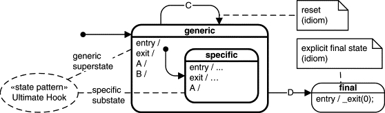
A diagram like this attempts to convey an abstract pattern but can only show a concrete example (instance) of the pattern. In this instance, the concrete “generic” state in Figure 5.1 handles events A and B as internal transitions, event C as a transition to self, and event D as the termination of the state machine. The concrete “specific” state overrides event A and provides its own initialization and cleanup (in entry and exit actions, respectively). Of course, another instance of the pattern can implement completely different events and actions.
A few idioms worth noting are illustrated in this state diagram. First is the overall canonical structure of the state machine that, at the highest level, consists of only one composite state (the pattern role of the generic superstate). Virtually every application can benefit from having such a highest-level state because it is an ideal place for defining common policies subsequently inherited by the whole (arbitrary complex) submachine.
Note
As described in Section 2.3.2 in Chapter 2, every UML state machine is a submachine of an implicit top state and so has the canonical structure proposed here. However, because you cannot override the top state, you need another highest-level state that you can customize.
Within such a canonical structure, a useful idiom for resetting the state machine is an empty (actionless) transition to self in the “generic” superstate (transition C in Figure 5.1). Such a transition causes a recursive exit from all nested states (including the “generic” superstate), followed by initialization starting from the initial transition of the highest-level state. This way of resetting a state machine is perhaps the safest because it guarantees proper cleanup through the execution of exit actions and clean initialization by entry actions and nested initial transitions. Similarly, the safest way to terminate a state machine is through an explicit transition out of the generic superstate to a “final” state (transition D in Figure 5.1) because all pertinent exit actions are executed. The QEP event processor does not provide a generic final state (denoted as the bull's eye in the UML). Instead, the statechart in Figure 5.1 proposes an idiom, which consists of an explicit state named “final” with an application-specific termination coded in its entry action.1 The calculator HSM designed in Chapter 2 and coded in Chapter 4 provides an example of the canonical state machine structure that uses the idioms to reset and terminate.
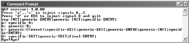
The sample code for the Ultimate Hook state pattern is found in the directory <qp>qpcexamples80x86dos cpp101lhook. You can execute the application by double-clicking the file HOOK.EXE file in the dbg subdirectory. Figure 5.2 shows the output generated by the HOOK.EXE application. Listing 5.1 shows the example implementation of the Ultimate Hook pattern from Figure 5.1.
Listing 5.1. The Ultimate Hook sample code (file hook.c).
typedef struct UltimateHookTag { /* UltimateHook state machine */(3)
QState UltimateHook_initial (UltimateHook *me, QEvent const *e);(3)
QState UltimateHook_generic (UltimateHook *me, QEvent const *e);(3)
QState UltimateHook_specific (UltimateHook *me, QEvent const *e);(3)
QState UltimateHook_final (UltimateHook *me, QEvent const *e);(4)
enum UltimateHookSignals { /* enumeration of signals */(4)
/*.............................................................*/(4)
void UltimateHook_ctor(UltimateHook *me) {(4)
QHsm_ctor(&me->super, (QStateHandler)&UltimateHook_initial);(4)
/*.............................................................*/(4)
QState UltimateHook_initial(UltimateHook *me, QEvent const *e) {(4)
return Q_TRAN(&UltimateHook_generic);(4)
/*.............................................................*/(4)
QState UltimateHook_final(UltimateHook *me, QEvent const *e) {(4)
      printf("final-ENTRY(terminate);
Bye!Bye!
");
(4)
return Q_SUPER(&QHsm_top);(4)
/*............................................................*/(4)
QState UltimateHook_generic(UltimateHook *me, QEvent const *e) {(6) return Q_TRAN(&UltimateHook_final);
(6)
return Q_SUPER(&QHsm_top);(6)
/*............................................................*/(6)
QState UltimateHook_specific(UltimateHook *me, QEvent const *e) {(9)
return Q_SUPER(&UltimateHook_generic); /* the superstate */
(1) Every QEP application needs to include
qep_porth.h(see Section 4.8 in Chapter 4).(3) The
UltimateHookdeclares theinitial()pseudostate and three state-handler functions:generic(),specific(), andfinal().(5) The transition-to-self in the “generic” state represents the reset idiom.
(6) The transition to the explicit “final” state represents the terminate idiom.
(7,8) The entry and exit actions in the “specific” state provide initialization and cleanup.
(9) The internal transition A in the “specific” state overrides the same transition in the “generic” superstate.
One option of deploying the Ultimate Hook pattern is to organize the code into a library that intentionally does not contain the implementation of the UltimateHook_specific() state-handler function. Clients would then have to provide their own implementation and link to the library to obtain the generic behavior. An example of a design using this technique is Microsoft Windows, which requires the client code to define the WinMain() function for the Windows application to link.
Another option for the C++ version is to declare the UltimateHook::specific() state handler as follows:
Where the member function UltimateHook::v_specific(QEvent const *e) is declared as a pure virtual member function in C++. This will force clients to provide implementation for the pure virtual state-handler function v_specific() by subclassing the UltimateHook class. This approach combines behavioral inheritance with traditional class inheritance. More precisely, Ultimate Hook represents, in this case, a special instance of the Template Method design pattern [GoF 95].
The Ultimate Hook state pattern is presented here in its most limited version — exactly as it is used in GUI systems (e.g., Microsoft Windows). In particular, neither the generic superstate nor the specific substate exhibits any interesting state machine topology. The only significant feature is hierarchical state nesting, which can be applied recursively within the “specific” substate. For example, at any level, a GUI window can have nested child windows, which handle events before the parent.
Even in this most limited version, however, the Ultimate Hook state pattern is a fundamental technique for reusing behavior. In fact, every state model using the canonical structure implicitly applies this pattern.
The Ultimate Hook state pattern has the following consequences:
• The “specific” substate needs to know only those events it overrides.
• New events can be added easily to the high-level “generic” superstate without affecting the “specific” substate.
• Removing or changing the semantics of events that clients already use is difficult.
• Propagating every event through many levels of nesting (if the “specific” substate has recursively nested substates) can be expensive.
The Ultimate Hook state pattern is closely related to the Template Method OO design pattern and can be generalized by applying inheritance of entire state machines.
Often in state modeling, loosely related functions of a system are strongly coupled by a common event. Consider, for example, periodic data acquisition, in which a sensor producing the data needs to be polled at a predetermined rate. Assume that a periodic TIMEOUT event is dispatched to the system at the desired rate to provide the stimulus for polling the sensor. Because the system has only one external event (the TIMEOUT event), it seems that this event needs to trigger both the polling of the sensor and the processing of the data. A straightforward but suboptimal solution is to organize the state machine into two distinct orthogonal regions (for polling and processing).2 This example illustrates an alternative design for the Polling state pattern described in [Douglass 99]. However, orthogonal regions increase the cost of dispatching events (see the “Orthogonal Component” pattern) and require complex synchronization between the regions because polling and processing are not quite independent.
A simpler and more efficient solution is to invent a stimulus (DATA_READY) and to propagate it to self as a reminder that the data is ready for processing (Figure 5.3). This new stimulus provides a way to decouple polling from processing without using orthogonal regions. Moreover, you can use state nesting to arrange these two functions in a hierarchical relation,3 Using state hierarchy in this fashion is typically more efficient than using orthogonal regions. which gives you even more control over the behavior.
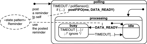
In the most basic arrangement, the “processing” state can be a substate of “polling” and can simply inherit the “polling” behavior so that polling occurs in the background to processing. However, the “processing” state might also choose to override polling. For instance, to prevent flooding the CPU with sensor data, processing might inhibit polling occasionally. The statechart in Figure 5.3 illustrates this option. The “busy” substate of “processing” overrides the TIMEOUT event and thus prevents this event from being handled in the higher-level “polling” superstate.
Further flexibility of this solution entails fine control over the generation of the invented DATA_READY event, which does not have to be posted at every occurrence of the original TIMEOUT event. For example, to improve performance, the “polling” state could buffer the raw sensor data and generate the DATA_READY event only when the buffer fills up. Figure 5.3 illustrates this option with the if (…) condition, which precedes the postFIFO(me, DATA_READY) action in the “polling” state.
The sample code for the Reminder state pattern is found in the directory <qp>qpcexamples80x86dos cpp101l
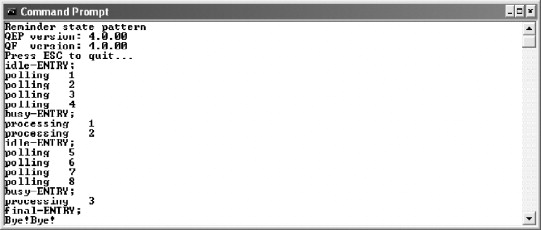
eminder. You can execute the application by double-clicking on the file REMINDER.EXE file in the dbg subdirectory. Figure 5.4 shows the output generated by the REMINDER.EXE application. The application prints every state entry (to “busy” or “idle”) as well as the number of times the TIMEOUT event has been handled in “polling” and “processing,” respectively. Listing 5.2 shows the example implementation of the Reminder pattern from Figure 5.3.
Listing 5.2. The Reminder sample code (file reminder.c)
(2) DATA_READY_SIG, /* the invented reminder signal */
(2)
TERMINATE_SIG /* terminate the application */(2)
/*. . . . . . . . . . . . . */(2)
typedef struct SensorTag { /* the Sensor active object */
/* hierarchical state machine ... */
QState Sensor_initial (Sensor *me, QEvent const *e);
QState Sensor_polling (Sensor *me, QEvent const *e);
QState Sensor_processing(Sensor *me, QEvent const *e);
QState Sensor_idle (Sensor *me, QEvent const *e);(5) QTimeEvt_ctor(&me->timeEvt, TIMEOUT_SIG); /* time event ctor */
(5)
/* HSM definition----------------------------------------------*/(6)
return Q_TRAN(&Sensor_polling);(6)
/*............................................................*/(6)
QState Sensor_final(Sensor *me, QEvent const *e) {(6)
     printf("final-ENTRY;
Bye!Bye!
");
(6)
BSP_exit(); /* terminate the application */(6)
return Q_SUPER(&QHsm_top);(6)
/*............................................................*/(7) QTimeEvt_postEvery(&me->timeEvt, (QActive *)me,
(7)
QTimeEvt_disarm(&me->timeEvt);(8)
static const QEvent reminderEvt = { DATA_READY_SIG, 0 };(9) QActive_postFIFO((QActive *)me, &reminderEvt);
(9)
return Q_TRAN(&Sensor_final);(9)
return Q_SUPER(&QHsm_top);(9)
/*............................................................*/(9)
QState Sensor_processing(Sensor *me, QEvent const *e) {(9)
return Q_TRAN(&Sensor_idle);(9)
return Q_SUPER(&Sensor_polling);(9)
/*..............................................................*/(10)
return Q_TRAN(&Sensor_busy);(10)
return Q_SUPER(&Sensor_processing);(10)
/*..............................................................*/(11)
     printf("processing %3d
", me->procCtr);
(11)
if ((me->procCtr & 0x1) == 0) {/* modulo 2 */(11)
return Q_TRAN(&Sensor_idle);
The Reminder state pattern posts the reminder event to self. This operation involves event queuing and is not supported by the raw QEP event processor. Therefore the sample code uses the QEP event processor as well as the QF real-time framework, which are both components of the QP event-driven platform. The QF component provides event queuing as well as the time events, both of which are used in the sample code.
(1) The Reminder state pattern posts the reminder event to self. This operation involves event queuing and is not supported by the raw QEP event processor. The sample code uses the whole QP, which includes the QEP event processor and the QF real-time framework. QF provides event queuing as well as the time events, both of which are used in the sample code.
Note
Event queuing and event-driven timing services are available in virtually every event-driven infrastructure. For instance, Windows GUI applications can call the
PostMessage()Win32 API to queue messages and theWM_TIMERmessage to receive timer updates.
(2) The invented reminder event signal (
DATA_READYin this case) is enumerated just like all other signals in the system.(3) The
Sensorstate machine derives from the QF classQActivethat combines an HSM, an event queue, and a thread of execution. TheQActiveclass actually derives fromQHsm, which means thatSensoralso indirectly derives fromQHsm(see Chapter 6 for more details).(4) The
Sensorstate machine declares its own private time event. Time events are managed by the QF real-time framework. Section 7.7 in Chapter 7 covers theQTimeEvtfacility in detail.(5) The time event must be instantiated, at which time it gets permanently associated with the given signal (
TIMEOUT_SIGin this case).(6) The topmost initial transition enters the “polling” state, which in turn enters the “idle” substate.
(7) Upon entry to the “polling” state, the time event is armed for generating periodic
TIMEOUT_SIGevents twice per second.(8) After being armed, the time event produces the
TIMEOUT_SIGevents at the programmed rate. Because neither the “idle” state nor the “processing” state handle theTIMEOUT_SIGsignal, the signal is handled initially in the “polling” superstate.(9) At a lower rate (every fourth time, in this example), the “polling” state generates the reminder event (
DATA_READY), which it posts to self. Event posting occurs by calling theQActive_postFIFO()function provided in the QF real-time framework.(10) The reminder event causes a transition from “idle” to “busy.”
(11) The “busy” state overrides the
TIMEOUT_SIGsignal and after a fewTIMEOUTevents transitions back to “idle.” The cycle then repeats.
Although conceptually very simple, the Reminder state pattern has profound consequences. It can address many more problems than illustrated in the example. You could use it as a “Swiss Army knife” to fix almost any problem in the state machine topology.
For example, you also can apply the Reminder idiom to eliminate troublesome completion transitions, which in the UML specification are transitions without an explicit trigger (they are triggered implicitly by completion events, a.k.a. anonymous events). The QEP event processor requires that all transitions have explicit triggers; therefore, the QEP does not support completion transitions. However, the Reminder pattern offers a workaround. You can invent an explicit trigger for every transition and post it to self. This approach actually gives you much better control over the behavior because you can explicitly specify the completion criteria.
Yet another important application of the Reminder pattern is to break up longer RTC steps into shorter ones. As explained in more detail in Chapter 6, long RTC steps exacerbate the responsiveness of a state machine and put more stress on event queues. The Reminder pattern can help you break up CPU-intensive processing (e.g., iteration) by inventing a stimulus for continuation in the same way that you stick a Post-It note to your computer monitor to remind you where you left off on some lengthy task when someone interrupts you. You can also invent event parameters to convey the context, which will allow the next step to pick up where the previous step left off (e.g., the index of the next iteration). The advantage of fragmenting lengthy processing in such a way is that other (perhaps more urgent) events can “sneak in,” allowing the state machine to handle them in a more timely way.
You have essentially two alternatives when implementing event posting: the first-in, first-out (FIFO) or the last-in, first-out (LIFO) policy, both of which are supported in the QF real-time framework (see Chapter 6). The FIFO policy is appropriate for breaking up longer RTC steps. You want to queue the Reminder event after other events that have potentially accumulated while the state machine was busy, to give the other events a chance to sneak in ahead of the Reminder. However, in other circumstances, you might want to process an uninterruptible sequence of posted events (such a sequence effectively forms an extended RTC step4 For example, state-based exception handling (see Section 6.7.4 in Chapter 6) typically requires immediate handling of exceptional situations, so you don't want other events to overtake the EXCEPTION event.). In this case, you need the LIFO policy because a reminder posted with that policy is guaranteed to be the next event to process and no other event can overtake it.
Note
You should always use the LIFO policy with great caution because it changes the order of events. In particular, if multiple events are posted with the LIFO policy to an event queue and no events are removed from the queue in the meantime, the order of these events in the queue will get reversed.
One of the biggest challenges in designing reactive systems is that such systems must be prepared to handle every event at any time. However, sometimes an event arrives at a particularly inconvenient moment when the system is in the midst of some complex event sequence. In many cases, the nature of the event is such that it can be postponed (within limits) until the system is finished with the current sequence, at which time the event can be recalled and conveniently processed.
Consider, for example, the case of a server application that processes transactions (e.g., from ATM5 ATM stands for automated teller machine, a.k.a. cash machine. terminals). Once a transaction starts, it typically goes through a sequence of processing, which commences with receiving the data from a remote terminal followed by the authorization of the transaction. Unfortunately, new transaction requests to the server arrive at random times, so it is possible to get a request while the server is still busy processing the previous transaction. One option is to ignore the request, but this might not be acceptable. Another option is to start processing the new transaction immediately, which can complicate things immensely because multiple outstanding transactions would need to be handled simultaneously.
The solution is to defer the new request and handle it at a more convenient time, which effectively leads to altering the sequence of events presented to the state machine.
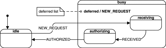
UML statecharts support such a mechanism directly (see Section 2.3.11 in Chapter 2) by allowing every state to specify a list of deferred events. As long as an event is on the combined deferred list of the currently active state configuration, it is not presented to the state machine but instead is queued for later processing. Upon a state transition, events that are no longer deferred are automatically recalled and dispatched to the state machine.
Figure 5.5 illustrates a solution based on this mechanism. The transaction server state machine starts in the “idle” state. The NEW_REQUEST event causes a transition to a substate of the “busy” state. The “busy” state defers the NEW_REQUEST event (note the special “deferred” keyword in the internal transition compartment of the “busy” state). Any NEW_REQUEST arriving when the server is still in one of the “busy” substates gets automatically deferred. Upon the transition AUTHORIZED back to the “idle” state, the NEW_REQUEST is automatically recalled. The request is then processed in the “idle” state, just as any other event.
Note
Hierarchical state nesting immensely complicates event deferral because the deferred lists in all superstates of the current state contribute to the mechanism.
The lightweight QEP event processor does not support the powerful, but heavyweight, event deferral mechanism of the UML specification. However, you can achieve identical functionality by deferring and recalling events explicitly. In fact, the QF real-time framework supports event deferral by providing defer() and recall() operations.
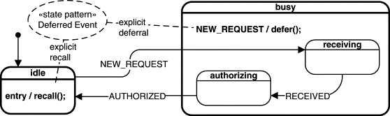
Figure 5.6 shows how to integrate the explicit defer() and recall() operations into a HSM to achieve the desired effect. The internal transition NEW_REQUEST in the “busy” state traps any NEW_REQUEST received in any of the substates. This internal transition calls the defer() operation to postpone the event. The “idle” state explicitly recalls any deferred events by calling recall() in the entry action. The recall() operation posts the first of the deferred events (if available) to self. The state machine then processes the recalled event just as any other event.
Note
Even though the deferred event is in principle available directly from the
recall()operation, it is not processed in the entry action to “idle.” Rather, therecall()operation posts the event to self (to the event queue of this state machine). The state machine then handles theNEW_REQUESTevent as any other event, that is, in the transition from “idle” to “receiving.”
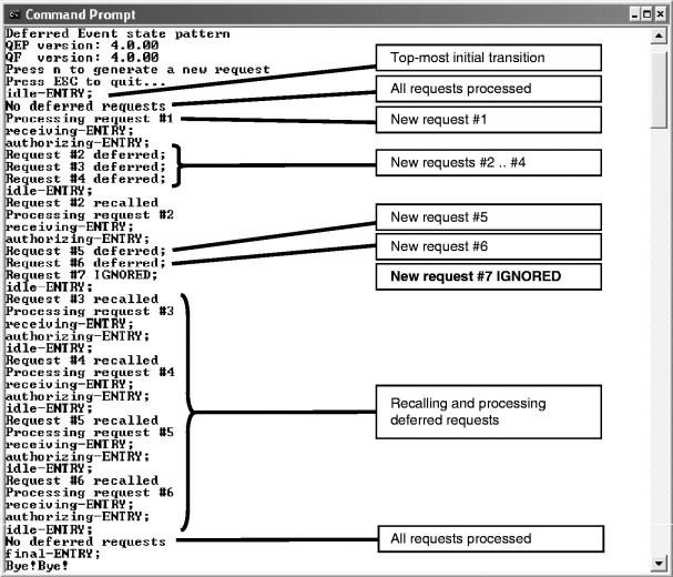
The sample code for the Deferred Event state pattern is found in the directory <qp>qpcexamples80x86dos cpp101ldefer. You can execute the application by double-clicking the file DEFER.EXE file in the dbg subdirectory. Figure 5.7 shows the output generated by the DEFER.EXE application. The application prints every state entry (to “idle,” “receiving,” and “authorizing”). Additionally, you get notification of every NEW_REQUEST event and whether it has been deferred or processed directly. You generate new requests by pressing the n key. Note that request #7 is not deferred because the deferred event queue gets full. See the explanation section following Listing 5.3 for an overview of options to handle this situation.
Listing 5.3. The Deferred Event sample code (file defer.c)
/*.......................................................................*/NEW_REQUEST_SIG = Q_USER_SIG,/* the new request signal */
RECEIVED_SIG,/* the request has been received */
AUTHORIZED_SIG,/* the request has been authorized */
TERMINATE_SIG/* terminate the application */
/*......................................................................*/(2)
typedef struct RequestEvtTag {(2)
QEvent super; /* derive from QEvent */
/*......................................................................*/(3)
typedef struct TServerTag { /* Transaction Server active object */(5)
QEQueue requestQueue; /* native QF queue for deferred request events */(6)
QEvent const *requestQSto[3]; /* storage for the deferred queue buffer */(8)
QTimeEvt authorizedEvt; /* private time event generator */} TServer;
void TServer_ctor(TServer *me);/* the default ctor */
/* hierarchical state machine ... */
QState TServer_initial (TServer *me, QEvent const *e);
QState TServer_idle (TServer *me, QEvent const *e);
QState TServer_busy (TServer *me, QEvent const *e);
QState TServer_receiving (TServer *me, QEvent const *e);
/*......................................................................*/(9) QEQueue_init(&me->requestQueue,
(9) me->requestQSto, Q_DIM(me->requestQSto));
(9)
QTimeEvt_ctor(&me->receivedEvt, RECEIVED_SIG);(9)
QTimeEvt_ctor(&me->authorizedEvt, AUTHORIZED_SIG);(9)
/* HSM definition -------------------------------------------------------*/(9)
QState TServer_initial(TServer *me, QEvent const *e) {(9)
(void)e; /* avoid the compiler warning about unused parameter */(9)
return Q_TRAN(&TServer_idle);(9)
/*......................................................................*/(9)
QState TServer_final(TServer *me, QEvent const *e) {(9)
(void)me; /* avoid the compiler warning about unused parameter */(9)
     printf("final-ENTRY;
Bye!Bye!
");
(9)
BSP_exit();/* terminate the application */(9)
return Q_SUPER(&QHsm_top);(9)
/*............................................................................*/(10) rq = (RequestEvt const *)QActive_recall((QActive *)me, &me->requestQueue);
(10)
if (rq != (RequestEvt *)0) { /* recall posted an event? */(12)
       printf("No deferred requests
");
(12)
      printf("Processing request #%d
",
(12)
(int)((RequestEvt const *)e)->refNum);(12)
return Q_TRAN(&TServer_receiving);(12)
return Q_TRAN(&TServer_final);(12)
return Q_SUPER(&QHsm_top);(12)
/*......................................................................*/(13)
if (QEQueue_getNFree(&me->requestQueue) > 0) { /* can defer? */(14) QActive_defer((QActive *)me, &me->requestQueue, e);
(14)
       printf("Request #%d deferred;
",
(14)
(int)((RequestEvt const *)e)->ref_num);(14) /* notify the request sender that the request was ignored.. */
(15)
      printf("Request #%d IGNORED;
",
(15)
(int)((RequestEvt const *)e)->ref_num);(15)
return Q_TRAN(&TServer_final);(15)
return Q_SUPER(&QHsm_top);(15)
/*.....................................................................*/(15)
QState TServer_receiving(TServer *me, QEvent const *e) {(15)
     printf("receiving-ENTRY;
");                                                /* one-shot timeout in 1 second */
(15)
QTimeEvt_fireIn(&me->receivedEvt, (QActive *)me,(15)
QTimeEvt_disarm(&me->receivedEvt);(15)
return Q_TRAN(&TServer_authorizing);(15)
return Q_SUPER(&TServer_busy);(15)
/*.....................................................................*/(15)
QState TServer_authorizing(TServer *me, QEvent const *e) {(15)
     printf("authorizing-ENTRY;
");
(15)
/* one-shot timeout in 2 seconds */(15)
QTimeEvt_fireIn(&me->authorizedEvt, (QActive *)me,(15)
QTimeEvt_disarm(&me->authorizedEvt);(15)
return Q_TRAN(&TServer_idle);
(1) The Deferred Event state pattern relies heavily on event queuing, which is not supported by the raw QEP event processor. The sample code uses the whole QP, which includes the QEP event processor and the QF real-time framework. QF provides specific direct support for deferring and recalling events.
(2) The
RequestEvtevent has a parameterref_num(reference number) that uniquely identifies the request.(3,4) The transaction server (
TServer) state machine derives from the QF classQActivethat combines an HSM, an event queue, and a thread of execution. TheQActiveclass actually derives fromQHsm, which means thatTServeralso indirectly derives fromQHsm.(5) The QF real-time framework provides a “raw” thread-safe event queue class
QEQueuethat is needed to implement event deferral. Here theTServerstate machine declares the privaterequestQueueevent queue to store the deferred request events. TheQEQueuefacility is discussed in Section 7.8.3 of Chapter 7.(6) The
QEQueuerequires storage for the ring buffer, which the user must provide, because only the application designer knows how to size this buffer. Note that event queues in QF store just pointers toQEvent, not the whole event objects.(7,8) The delays of receiving the whole transaction request (
RECEIVED) and receiving the authorization notification (AUTHORIZED) are modeled in this example with the time events provided in QF.(9) The private
requestQueueevent queue is initialized and given its buffer storage.(10) Per the HSM design, the entry action to the “idle” state recalls the request events. The function
QActive_recall()returns the pointer to the recalled event, orNULLif no event is currently deferred.Note
Even though you can “peek” inside the recalled event, you should not process it at this point. By the time
QActive_recall()function returns, the event is already posted to the active object's event queue using the LIFO policy, which guarantees that the recalled event will be the very next to process. (If other events were allowed to overtake the recalled event, the state machine might transition to a state where the recalled event would no longer be convenient.) The state machine will then handle the event like any other request coming at the convenient time. This is the central point of the Deferred Event design pattern.(11,12) The recalled event is inspected only to notify the user but not to handle it.
(13) Before the “busy” superstate defers the request, it checks to see whether the private event queue can accept a new deferred event.
(14) If so, the event is deferred by calling the
QActive_defer()QF function.(15) Otherwise, the request is ignored and the user is notified about this fact.
Note
Losing events like this is often unacceptable. In fact, the default policy of QF is to fail an internal assertion whenever an event could be lost. In particular, the
QActve_defer()function would fire an internal assertion if the event queue could not accept the deferred event. You can try this option by commenting out theifstatement in Listing 5.3(13).
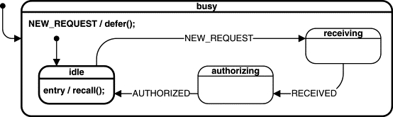
Figure 5.8 shows a variation of the Deferred Event state pattern, in which the state machine has the “canonical” structure recommended by the Ultimate Hook pattern. The “busy” state becomes the superstate of all states, including “idle.” The “idle” substate overrides the NEW_REQUEST event. All other substates of “busy” rely on the default event handling inside the “busy” superstate, which defers the NEW_REQUEST event. You can very easily try this option by reparenting the “idle” state. You simply change “return Q_SUPER(&QHsm_top)” to “return Q_SUPER(&TServer_busy)” in the TServer_idle() state-handler function.
Finally, I'd like to point out the true convenience of the QActive_defer() and QActive_recall() functions. The main difficulty in implementing the event deferral mechanism is actually not the explicit deferring and recalling but rather the memory management for the event objects. Consider, for example, that each request event must occupy some unique memory location, yet you don't know how long the event will be used. Some request events could be recycled just after the RTC step of the TServer state machine, but some will be deferred and thus will be used much longer. Recall that for memory efficiency and best performance the deferred event queue, as well as the queues of active objects in QF, store only pointers to events, not the whole event objects. How do you organize and manage memory for events?
This is where the QF real-time framework comes in. QF takes care of all the nitty-gritty details of managing event memory and does it very efficiently with “zero-copy” policy and in a thread-safe manner. As I will explain in Chapter 7, QF uses efficient event pools combined with a standard reference-counting algorithm to know when to recycle events back to the pools. The functions QActive_defer() and QActive_recall() participate in the reference-counting process so that QF does not recycle deferred events prematurely.
The whole event management mechanism is remarkably easy to use. You dynamically allocate an event, fill in the event parameters, and post it. QF takes care of the rest. In particular, you never explicitly recycle the event. Listing 5.4 shows how the request events are generated in the sample code for the Deferred Event pattern.
Listing 5.4. Generation of new request events with the Q_NEW() macro (file defer.c)
(1) When you press the n key, the QF macro
Q_NEW()creates a newRequestEvtevent and assigns it the signalNEW_REQUEST_SIG. The new event is allocated from an “event pool” that the application allocates at startup.(2) You fill in the event parameters. Here the
ref_numparameter is set from the incremented static counter.(3) You post the event to an active object, such as the local
l_tserverobject.(4) Constant, never-changing events can be allocated statically. Such events should have always the
dynamic_attribute set to zero (see Listing 4.1 and Section 4.3 in Chapter 4).(5) You post such static event just like any other event. The QF real-time framework knows not to manage the static events.
Event deferral is a valuable technique for simplifying state models. Instead of constructing an unduly complex state machine to handle every event at any time, you can defer an event when it comes at an inappropriate or awkward time. The event is recalled when the state machine is better able to handle it. The Deferred Event state pattern is a lightweight alternative to the powerful but heavyweight event deferral of UML statecharts. The Deferred Event state pattern has the following consequences.
• It requires explicit deferring and recalling of the deferred events.
• The QF real-time framework provides generic
defer() andrecall()operations.• If a state machine defers more than one event type, it might use the same event queue (
QEQueue) or different event queues for each event type. The generic QFdefer()andrecall()operations support both options.• Events are deferred in a high-level state, often inside an internal transition in this state.
• Events are recalled in the entry action to the state that can conveniently handle the deferred event type.
• The event should not be processed at the time it is explicitly recalled. Rather, the
recall()operation posts it using the LIFO policy so that the state machine cannot change state before processing the event.• Recalling an event involves posting it to self; however, unlike the Reminder pattern, deferred events are usually external rather than invented.
The Real-Time Object-Oriented Modeling (ROOM) method [Selic+ 94] supports a variation of the Deferred Event pattern presented here. Just like the QF real-time framework, the ROOM virtual machine (infrastructure for executing ROOM models) provides the generic methods defer() and recall(), which clients need to call explicitly. The ROOM virtual machine also takes care of event queuing. Operations defer() and recall() in ROOM are specific to the interface component through which an event was received.
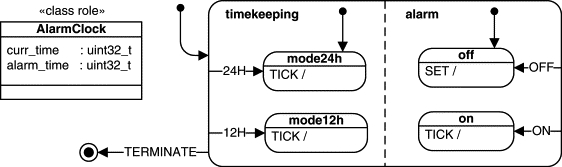
Many objects consist of relatively independent parts that have state behavior. As an example, consider a simple digital alarm clock. The device performs two largely independent functions: a basic timekeeping function and an alarm function. Each of these functions has its own modes of operation. For example, timekeeping can be in two modes: 12-hour or 24-hour. Similarly, the alarm can be either on or off.
The standard way of modeling such behavior in UML statecharts is to place each of the loosely related functions in a separate orthogonal region, as shown in Figure 5.9. Orthogonal regions are a relatively expensive mechanism6 Each orthogonal region requires a separate state variable (RAM) and some extra effort in dispatching events (CPU cycles). that the current implementation of the QEP event processor does not support. In addition, orthogonal regions aren't often the desired solution because they offer little opportunity for reuse. You cannot reuse the “alarm” orthogonal region easily outside the context of the AlarmClock state machine.
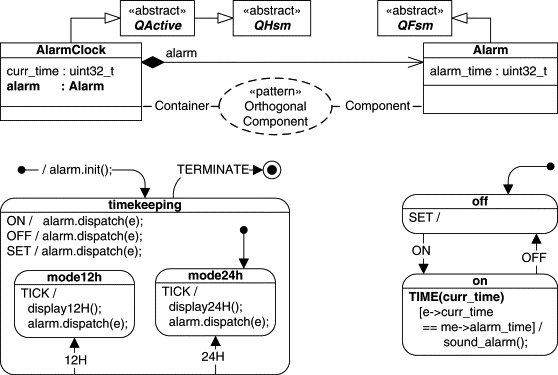
You can use object composition instead of orthogonal regions. As shown in Figure 5.10, the alarm function very naturally maps to the Alarm class that has both data (alarm_time) and behavior (the state machine). Indeed, Rumbaugh and colleagues [Rumbaugh+ 91] observe that this is a general rule. Concurrency virtually always arises within objects by aggregation; that is, multiple states of the components can contribute to a single state of the composite object.
The use of aggregation in conjunction with state machines raises three questions:
The composite object interacts with its aggregate parts by synchronously dispatching events to them (by invoking dispatch() on behalf of the components). GUI systems, for instance, frequently use this model because it is how parent windows communicate with their child windows (e.g., dialog controls). Although, in principle, the container could invoke various functions of its components or access their data directly, dispatching events to the components should be the preferred way of communication. The components are state machines, and their behavior depends on their internal state.
You can view the event-dispatching responsibility as a liability given that errors will result if the container “forgets” to dispatch events in some states, but you can also view it as an opportunity to improve performance. Explicit event dispatching also offers more flexibility than the event dispatching of orthogonal regions because the container can choose the events it wants to dispatch to its components and even change the event type on the fly. I demonstrate this aspect, when the AlarmClock container generates the TimeEvt on the fly before dispatching it to the Alarm components (see Listing 5.8(9)).
Listing 5.8. AlarmClock state machine definition (file clock.c)
/*.....................................................................*/
typedef struct AlarmClockTag { /* the AlarmClock active object */
uint32_t current_time; /* the current time in seconds */
QTimeEvt timeEvt; /* time event generator (generates time ticks) */
void AlarmClock_ctor(AlarmClock *me); /* default ctor */
/* hierarchical state machine ... */
QState AlarmClock_initial (AlarmClock *me, QEvent const *e);
QState AlarmClock_timekeeping(AlarmClock *me, QEvent const *e);
QState AlarmClock_mode12hr (AlarmClock *me, QEvent const *e);
QState AlarmClock_mode24hr (AlarmClock *me, QEvent const *e);
/*.....................................................................*/
void AlarmClock_ctor(AlarmClock *me) { /* default ctor */
QActive_ctor(&me->super, (QStateHandler)&AlarmClock_initial);(5) Alarm_ctor(&me->alarm); /* orthogonal component ctor */
(5)
QTimeEvt_ctor(&me->timeEvt, TICK_SIG); /* private time event ctor */(5)
/* HSM definition -------------------------------------------------------*/(5)
QState AlarmClock_initial(AlarmClock *me, QEvent const *e) {(5)
(void)e; /* avoid compiler warning about unused parameter */(6) Alarm_init(&me->alarm); /* the initial transition in the component */
(6)
return Q_TRAN(&AlarmClock_timekeeping);(6)
/*.....................................................................*/(6)
QState AlarmClock_final(AlarmClock *me, QEvent const *e) {(6)
(void)me; /* avoid the compiler warning about unused parameter */(6)
                printf("-> final
Bye!Bye!
");
(6)
BSP_exit(); /* terminate the application */(6)
return Q_SUPER(&QHsm_top);(6)
/*.....................................................................*/(6)
QState AlarmClock_timekeeping(AlarmClock *me, QEvent const *e) {(6)
/* periodic timeout every second */(6)
QTimeEvt_fireEvery(&me->timeEvt,(6)
(QActive *)me, BSP_TICKS_PER_SEC);(6)
QTimeEvt_disarm(&me->timeEvt);(6)
return Q_TRAN(&AlarmClock_mode24hr);(6)
return Q_TRAN(&AlarmClock_mode12hr);(6)
return Q_TRAN(&AlarmClock_mode24hr);(6)
/* synchronously dispatch to the orthogonal component */(7) Alarm_dispatch(&me->alarm, e);
(7)
return Q_TRAN(&AlarmClock_final);(7)
return Q_SUPER(&QHsm_top);(7)
/*.....................................................................*/(7)
QState AlarmClock_mode24hr(AlarmClock *me, QEvent const *e) {(8)
TimeEvt pe; /* temporary synchronous event for the component */(8)
if (++me->current_time == 24*60) { /* roll over in 24-hr mode? */(10)
pe.current_time = me->current_time;(10)
/* synchronously dispatch to the orthogonal component */(11) Alarm_dispatch(&me->alarm, (QEvent *)&pe);
(11)
return Q_SUPER(&AlarmClock_timekeeping);(11)
/*.....................................................................*/(11)
QState AlarmClock_mode12hr(AlarmClock *me, QEvent const *e) {(11)
                printf("*** 12-hour mode
");
(11)
TimeEvt pe; /* temporary synchronous event for the component */
if (++me->current_time == 12*60) { /* roll over in 12-hr mode? */
                printf("%02ld:%02ld %s
", (h % 12) ? (h % 12) : 12,
me->current_time % 60, (h / 12) ? "PM" : "AM");
((QEvent *)&pe)->sig = TICK_SIG;
pe.current_time = me->current_time;
/* synchronously dispatch to the orthogonal component */Alarm_dispatch(&me->alarm, (QEvent *)&pe);
To communicate in the opposite direction (from a component to the container), a component needs to post events to the container. Note that a component cannot call dispatch() on behalf of the container because this would violate RTC semantics. As a rule, the container is always in the middle of its RTC step when a component executes. Therefore, components need to asynchronously post (queue) events to the container.
This way of communication corresponds to a concurrency model in which a container shares its execution thread with the state machine components.7 Most commonly, all orthogonal regions in a UML statechart also share a common execution thread [Douglass 99]. The container dispatches an event to a component by synchronously calling dispatch() state machine operation on behalf of the component. Because this function executes in the container's thread, the container cannot proceed until dispatch() returns, that is, until the component finishes its RTC step. In this way, the container and components can safely share data without any concurrency hazards (data sharing is also another method of communication among them). However, sharing the container's data makes the components dependent on the container and thus makes them less reusable.
As you can see on the right side of Figure 5.10, I decided to derive the Alarm component from the simpler QFsm base class to demonstrate that you have a choice of the base class for the components. You can decide to implement some components as HSMs and others as FSMs. The QEP event processor supports both options.
By implementing half of the problem (the AlarmClock container) as a hierarchical state machine and the other half as a classical “flat” FSM (the Alarm component), I can contrast the hierarchical and nonhierarchical solutions to essentially identical state machine topologies. Figure 5.10 illustrates the different approaches to representing mode switches in the HSM and in the FSM. The hierarchical solution demonstrates the “Device Mode” idiom [Douglass 99], in which the signals 12H and 24H trigger high-level transitions from the “timekeeping” superstate to the substates “mode12h” and “mode24h,” respectively. The Alarm FSM is confined to only one level and must use direct transitions ON and OFF between its two modes. Although it is not clearly apparent with only two modes, the number of mode-switch transitions in the hierarchical technique scales up proportionally to the number of modes, n. The nonhierarchical solution requires many more transitions—n × (n – 1), in general—to interconnect all states. There is also a difference in behavior. In the hierarchical solution, if a system is already in “mode12h,” for example, and the 12H signal arrives, the system leaves this mode and re-enters it again. (Naturally, you could prevent that by overriding the high-level 12H transition in the “mode12h” state.) In contrast, if the flat state machine of the Alarm class is in the “off” state, for example, then nothing happens when the OFF signal appears. This solution might or might not be what you want, but the hierarchical solution (the Device Mode idiom) offers you both options and scales much better with a growing number of modes.
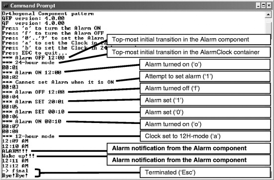
The sample code for the Orthogonal Component state pattern is found in the directory <qp>qpcexamples80x86dos cpp101lcomp. You can execute the application by double-clicking the file COMP.EXE file in the dbg subdirectory. Figure 5.11 shows the output generated by the COMP.EXE application. The application prints the status of every mode change, both in the AlarmClock container and in the Alarm component. Additionally, you get feedback about the currently set alarm time and a notification when the alarm time is reached. The legend of the keystrokes at the top of the screen describes how to generate events for the application. Also, note that to make things happen a little faster, I made this alarm clock advance by one accelerated minute per one real second.
The sample code demonstrates the typical code organization for the Orthogonal Component state pattern, in which the component (Alarm) is implemented in a separate module from the container (AlarmClock). The modules are coupled through shared signals, events, and variables (Listing 5.5). In particular, the pointer to the container active object APP_alarmClock is made available to all components so that they can post events to the AlarmClock container.
Listing 5.5. Common signals and events (file clock.h)
TICK_SIG = Q_USER_SIG, /* time tick event */
ALARM_SET_SIG, /* set the alarm */
ALARM_ON_SIG, /* turn the alarm on */
ALARM_OFF_SIG, /* turn the alarm off */
ALARM_SIG, /* alarm event from Alarm component to AlarmClock container */
CLOCK_12H_SIG, /* set the clock in 12H mode */
/*.................................................................*/extern QActive *APP_alarmClock; /* AlarmClock container active object */
Note
Note that the
APP_alarmClockpointer has the generic typeQActive*. The components only “know” the container as a generic active object; they don't know its specific data structure or state-handler functions. This technique is called opaque pointer and is worth remembering for reducing dependencies among modules.
Listing 5.6 shows the declaration of the Alarm component (see Figure 5.10). Note that I don't actually need to expose the state-handler functions in the alarm.h header file. Instead, I provide only the generic interface to the Alarm component as the macros Alarm_init() and Alarm_dispatch() to let the container initialize and dispatch events to the component, respectively. This approach insulates the container from the choice of the base class for the component. If later on I decide to derive Alarm from QHsm, for example, I need to change only the definitions of the Alarm_init() and Alarm_dispatch() macros; I don't need to change the container code at all. Note that the macros are unnecessary in the C++ implementation because due to the compatibility between the QHsm and QFsm interfaces, the container state-handler functions always dispatch events to the Alarm component in the same way by calling me->alarm.dispatch().
Listing 5.6. Alarm component declaration (file alarm.h)
Listing 5.7 shows the implementation of the Alarmcomponent state machine.
Listing 5.7. Alarm state machine definition (file alarm.c)
(3)
QState Alarm_initial(Alarm *me, QEvent const *e);
/*......................................................................*/
/* HSM definition -------------------------------------------------------*/
QState Alarm_initial(Alarm *me, QEvent const *e) {
(void)e; /* avoid compiler warning about unused parameter */
/*......................................................................*/
QState Alarm_off(Alarm *me, QEvent const *e) {
/* while in the off state, the alarm is kept in decimal format */(5)
me->alarm_time = (me->alarm_time/60)*100 + me->alarm_time%60;(5)
       printf("*** Alarm OFF %02ld:%02ld
",
(5)
me->alarm_time/100, me->alarm_time%100);(5)
/* upon exit, the alarm is converted to binary format */(6)
me->alarm_time = (me->alarm_time/100)*60 + me->alarm_time%100;(6)
/* while setting, the alarm is kept in decimal format */(6)
uint32_t alarm = (10 * me->alarm_time(6)
+((SetEvt const *)e)->digit) % 10000;(6)
if ((alarm / 100 < 24) && (alarm % 100 < 60)) {/*alarm in range?*/(6)
else { /* alarm out of range -- start over */(6)
        printf("*** Alarm SET %02ld:%02ld
",
(6)
me->alarm_time/100, me->alarm_time%100);(6)
/*......................................................................*/(6)
QState Alarm_on(Alarm *me, QEvent const *e) {(6)
        printf("*** Alarm ON %02ld:%02ld
",
(6)
me->alarm_time/60, me->alarm_time%60);(6)
printf("*** Cannot set Alarm when it is ON ");(8)
QActive_postFIFO(APP_alarmClock, Q_NEW(QEvent, ALARM_SIG));
(1,2) The
Alarmcomponent needs both thealarm.hinterface and theclock.hcontainer interface.(3) The nonhierarchical state-handler functions have the same signature as the hierarchical state handlers (see Section 3.6 in Chapter 3).
(4) The
Alarmconstructor must invoke the constructor of its base class.(5) Upon the entry to the “off” state, the alarm time is converted to the decimal format, in which 12:05 corresponds to decimal 1205.
(6) Upon the exit from the “off” state, the alarm time is converted back to the binary format, in which 12:05 corresponds to 12 * 60 + 5 = 725.
Note
The guaranteed initialization and cleanup provided by the entry and exit actions ensure that the time conversion will always happen, regardless of the way the state “off” is entered or exited. In particular, the alarm time will be always represented in decimal format while in the “off” state and in binary format outside the “off” state.
(7) The
Alarmcomponent keeps receiving theTIMEevent from theAlarmClockcontainer.AlarmClockconveniently provides thecurrent_timeevent parameter, which theAlarmcomponent can directly compare to itsme->alarm_timeextended-state variable.(8) When the
Alarmcomponent detects the alarm time, it notifies the container by posting an event to it. Here I am using a global pointerAPP_alarmClockto the container active objects. An often used alternative is to store the pointer to the container inside each component.
(1,2) The
AlarmClockcontainer includes its own interfaceclock.has well as all interfaces to the component(s) it uses.(3) The
AlarmClockstate machine derives from the QF classQActivethat combines an HSM, an event queue, and a thread of execution. TheQActiveclass actually derives fromQHsm, which means thatAlarmClockalso indirectly derives fromQHsm.(5) The container must explicitly instantiate the components (in C).
(6) The container is responsible for initializing the components in its topmost initial transition.
(7) The container is responsible for dispatching the events of interest to the components. In this line, the container simply dispatches the current event
e.(8) The temporary
TimeEvtobject to be synchronously dispatched to the component can be allocated on the stack. Note that the ‘pe’ variable represents the wholeTimeEvtinstance, not just a pointer.(9,10) The container synthesizes the
TimeEvtobject on the fly and provides the current time.(11) The temporary event is directly dispatched to the component.
The Orthogonal Component state pattern has the following consequences.
• It partitions independent islands of behavior into separate state machine objects. This separation is deeper than with orthogonal regions because the objects have both distinct behavior and distinct data.
• Partitioning introduces a container–component (also known as parent–child or master–slave) relationship. The container implements the primary functionality and delegates other (secondary) features to the components. Both the container and the components are state machines.
• The components are often reusable with different containers or even within the same container (the container can instantiate more than one component of a given type).
• The container shares its execution thread with the components.
• The container communicates with the components by directly dispatching events to them. The components notify the container by posting events to it, never through direct event dispatching.
• The components typically use the Reminder state pattern to notify the container (i.e., the notification events are invented specifically for internal communication and are not relevant externally). If there are more components of a given type, the notification events must identify the originating component (the component passes its ID number in a parameter of the notification event).
• The container and components can share data. Typically, the data is a data member of the container (to allow multiple instances of different containers). The container typically grants friendship to the selected components.
• The container is entirely responsible for its components. In particular, it must explicitly trigger initial transitions in all components8 In C, the container also must explicitly instantiate all components explicitly by calling their “constructors.” as well as explicitly dispatch events to the components. Errors may arise if the container “forgets” to dispatch events to some components in some of its states.
• The container has full control over the dispatching of events to the components. It can choose not to dispatch events that are irrelevant to the components. It can also change event types on the fly and provide some additional information to the components.
• The container can dynamically start and stop components (e.g., in certain states of the container state machine).
• The composition of state machines is not limited to just one level. Components can have state machine subcomponents; that is, the components can be containers for lower-level subcomponents. Such a recursion of components can proceed arbitrarily deep.
The Orthogonal Component state pattern is popular in GUI systems. For example, dialog boxes are the containers that aggregate components in the form of dialog controls (buttons, check boxes, sliders, etc.). Both dialog boxes and dialog controls are event-driven objects with state behavior (e.g., a button has “depressed” and “released” states). GUIs also use the pattern recursively. For instance, a custom dialog box can be a container for the standard File-Select or Color-Select dialog boxes, which in turn contain buttons, check boxes, and so on.
The last example points to the main advantage of the Orthogonal Component state pattern over orthogonal regions. Unlike an orthogonal region, you can reuse a reactive component many times within one application and across many applications.
Transition out of a composite state, but remember the most recent active substate so you can return to that substate later.
State transitions defined in high-level composite states often deal with events that require immediate attention; however, after handling them, the system should return to the most recent substate of the given composite state.
For example, consider a simple toaster oven. Normally the oven operates with its door closed. However, at any time, the user can open the door to check the food or to clean the oven. Opening the door is an interruption; for safety reasons, it requires shutting the heater off and lighting an internal lamp. However, after closing the door, the toaster oven should resume whatever it was doing before the door was opened. Here is the problem: What was the toaster doing just before the door was opened? The state machine must remember the most recent state configuration that was active before opening the door in order to restore it after the door is closed again.
UML statecharts address this situation with two kinds of history pseudostates: shallow history and deep history (see Section 2.3.12 in Chapter 2). This toaster oven example requires the deep history mechanism (denoted as the circled H* icon in Figure 5.12). The QEP event processor does not support the history mechanism automatically for all states because it would incur extra memory and performance overheads. However, it is easy to add such support for selected states.
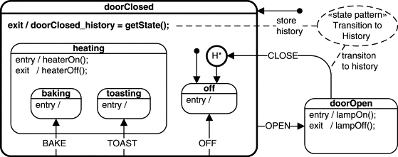
Figure 5.12 illustrates the solution, which is to store the most recently active leaf substate of the “doorClosed” state in the dedicated data member doorClosed_history (abbreviated to history in Figure 5.12). Subsequently, the Transition to History of the “doorOpen” state (transition to the circled H*) uses the attribute as the target of the transition.
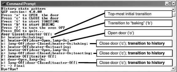
The sample code for the Transition to History state pattern is found in the directory <qp>qpcexamples80x86dos cpp101lhistory. You can execute the application by double-clicking the file HISTORY.EXE file in the dbg subdirectory. Figure 5.13 shows the output generated by the HISTORY.EXE application. The application prints the actions as they occur. The legend of the keystrokes at the top of the screen describes how to generate events for the application. For example, you open the door by typing o and close the door by typing c.
Listing 5.9 shows the implementation of the Transition to History pattern.
Listing 5.9. The Transition to History sample code (file history.c)
/*.....................................................................*/
OPEN_SIG = Q_USER_SIG, CLOSE_SIG,
TERMINATE_SIG /* terminate the application */
/*.....................................................................*/(2) QStateHandler doorClosed_history; /* history of the doorClosed state */
void ToasterOven_ctor(ToasterOven *me); /* default ctor */
QState ToasterOven_initial (ToasterOven *me, QEvent const *e);
QState ToasterOven_doorOpen (ToasterOven *me, QEvent const *e);
QState ToasterOven_off (ToasterOven *me, QEvent const *e);
QState ToasterOven_heating (ToasterOven *me, QEvent const *e);
QState ToasterOven_toasting (ToasterOven *me, QEvent const *e);
QState ToasterOven_baking (ToasterOven *me, QEvent const *e);
QState ToasterOven_doorClosed(ToasterOven *me, QEvent const *e);
QState ToasterOven_final (ToasterOven *me, QEvent const *e);
/*.....................................................................*/
void ToasterOven_ctor(ToasterOven *me) { /* default ctor */
QHsm_ctor(&me->super, (QStateHandler)&ToasterOven_initial);
/* HSM definitio -------------------------------------------------------*/
QState ToasterOven_initial(ToasterOven *me, QEvent const *e) {
(void)e; /* avoid compiler warning about unused parameter */(3) me->doorClosed_history = (QStateHandler)&ToasterOven_off;
(3)
return Q_TRAN(&ToasterOven_doorClosed);(3)
/*.....................................................................*/(3)
QState ToasterOven_final(ToasterOven *me, QEvent const *e) {(3)
(void)me; /* avoid compiler warning about unused parameter */(3)
                printf("-> final
Bye!Bye!
");
(3)
return Q_SUPER(&QHsm_top);(3)
/*.....................................................................*/(3)
QState ToasterOven_doorClosed(ToasterOven *me, QEvent const *e) {(3)
return Q_TRAN(&ToasterOven_off);(3)
return Q_TRAN(&ToasterOven_doorOpen);(3)
return Q_TRAN(&ToasterOven_toasting);(3)
return Q_TRAN(&ToasterOven_baking);(3)
return Q_TRAN(&ToasterOven_off);(3)
return Q_TRAN(&ToasterOven_final);(3)
return Q_SUPER(&QHsm_top);(3)
/*.....................................................................*/(3)
QState ToasterOven_off(ToasterOven *me, QEvent const *e) {(3)
(void)me; /* avoid compiler warning about unused parameter */(4) me->doorClosed_history = (QStateHandler)&ToasterOven_off;
(4)
return Q_SUPER(&ToasterOven_doorClosed);(4)
/*.....................................................................*/(4)
QState ToasterOven_heating(ToasterOven *me, QEvent const *e) {(4)
(void)me; /* avoid compiler warning about unused parameter */(4)
return Q_SUPER(&ToasterOven_doorClosed);(4)
/*.....................................................................*/(4)
QState ToasterOven_toasting(ToasterOven *me, QEvent const *e) {(4)
(void)me; /* avoid compiler warning about unused parameter */(5) me->doorClosed_history = (QStateHandler)&ToasterOven_toasting;
(5)
return Q_SUPER(&ToasterOven_heating);(5)
/*.....................................................................*/(5)
QState ToasterOven_baking(ToasterOven *me, QEvent const *e) {(5)
(void)me; /* avoid compiler warning about unused parameter */(6) me->doorClosed_history = (QStateHandler)&ToasterOven_baking;
(6)
return Q_SUPER(&ToasterOven_heating);(6)
/*.......................................................................*/ QState ToasterOven_doorOpen(ToasterOven *me, QEvent const *e) {(7) return Q_TRAN(me->doorClosed_history); /* transition to HISTORY */
(1) Every QEP application needs to include
qep_port.h(see Section 4.8 in Chapter 4).(2) The
ToasterOvenstate machine declares the history of the “doorClosed” state as a data member.(3) The
doorClosed_historyvariable is initialized in the topmost initial transition according to the diagram in Figure 5.12.(4-6) The entry actions to all leaf substates of the “doorClosed” state record the history of entering those substates in the
doorClosed_historyvariable. A leaf substate is a substate that has no further substates (see Section 2.3.8 in Chapter 2).(7) The transition to history is implemented with the standard macro
Q_TRAN(), where the target of the transition is thedoorClosed_historyvariable.
The transition to history state pattern has the following consequences:
• It requires that a separate
QHsmStatepointer to the state-handler function (history variable) is provided for each composite state to store the history of this state.• The Transition to History pseudostate (both deep and shallow history) is coded with the regular
Q_TRAN()macro, where the target is specified as the history variable.• Implementing the deep history pseudostate (see Section 2.3.12 in Chapter 2) requires explicitly setting the history variable in the entry action of each leaf substate of the corresponding composite state.
• Implementing the shallow history pseudostate (see Section 2.3.12 in Chapter 2) requires explicitly setting the history variable in each exit action from the desired level. For example, shallow history of the “doorClosed” state in Figure 5.12 requires setting
doorClosed_historyto&ToasterOven_toastingin the exit action from “toasting” to&ToasterOven_bakingin the exit action from “baking,” and so on for all direct substates of “doorClosed.”• You can explicitly clear the history of any composite state by resetting the corresponding history variable.
As Gamma and colleagues [GoF 95] observe: “One thing expert designers know not to do is solve every problem from first principles.” Collecting and documenting design patterns is one of the best ways of capturing and disseminating expertise in any domain, not just in software design.
State patterns are specific design patterns that are concerned with optimal (according to some criteria) ways of structuring states, events, and transitions to build effective state machines. This chapter described just five such patterns and a few useful idioms for structuring state machines. The first two patterns, Ultimate Hook and Reminder, are at a significantly lower level than the rest, but they are so fundamental and useful that they belong in every state machine designer's bag of tricks.
The other three patterns (Deferred Event, Orthogonal Component, and Transition to History) are alternative, lightweight realizations of features supported natively in the UML state machine package [OMG 07]. Each one of these state patterns offers significant performance and memory savings compared to the full UML-compliant realization.