Chapter Five
TCP/IP Addressing and Routing
Introduction
Transmission Control Protocol/Internet Protocol (TCP/IP) is so dominant that it warrants its own chapter. In fact, numerous other chapters in this book also provide coverage of the many aspects of TCP/IP. This chapter deals with TCP/IP addressing for both IPv4 and IPv6, MAC addressing, routing, and routing protocols. These are some of the common technologies network administrators work with daily. Expect the content presented in this chapter to be well represented on the Network+ exam. We start by looking at MAC addressing.
Identifying MAC Addresses
You already know that devices use MAC addresses, but you may not yet understand why MAC addresses exist, how they are assigned, and what they consist of. This section explains those details.
Tip
A MAC address is the physical address A MAC address is sometimes referred to as a physical address because it is physically embedded in the interface. Sometimes it is also referred to as a network address, which is incorrect. A network address is the logical protocol address assigned to the network to which the interface is connected.
A MAC address is a 6-byte (48-bit) hexadecimal address that allows a NIC to be uniquely identified on the network. The MAC address forms the basis of network communication, regardless of the protocol used to achieve network connection. Because the MAC address is so fundamental to network communication, mechanisms are in place to ensure no possibility of duplicate addresses.
To combat the possibility of duplicate MAC addresses being assigned, the Institute of Electrical and Electronics Engineers (IEEE) took over the assignment of MAC addresses. But rather than be burdened with assigning individual addresses, the IEEE instead decided to assign each manufacturer an ID and then let the manufacturer further allocate IDs. The result is that in a MAC address, the first three bytes define the manufacturer, and the manufacturer assigns the last three bytes.
For example, consider the MAC address of the computer on which this book is being written: 00:D0:59:09:07:51. The first three bytes (00:D0:59) identify the manufacturer of the card; because only this manufacturer can use this address, the first three bytes are known as the Organizational Unique Identifier (OUI). The last three bytes (09:07:51) are then referred to as the Universal LAN MAC address. They make this interface unique. You can find a complete listing of organizational MAC address assignments at http://standards.ieee.org/regauth/oui/oui.txt.
Exam Alert
MAC address tip Because MAC addresses are expressed in hexadecimal, only the numbers 0 through 9 and the letters A through F can be used. If you get a Network+ exam question about identifying a MAC address and some of the answers contain letters and numbers other than 0 through 9 and the letters A through F, you can discount those answers immediately.
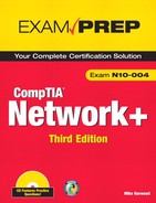
You can discover the MAC address of the NIC in various ways, depending on what system or platform you are working on. Table 5.1 defines various platforms and the method you can use to view the MAC address of an interface.
Table 5.1 Methods of Viewing the MAC Addresses of NICs
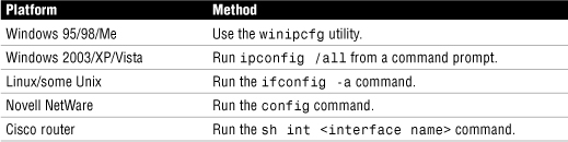
Figure 5.1 shows the ipconfig /all command run on a Windows server system. The MAC address is defined on the physical address line of the output.
Figure 5.1 The output from the ipconfig /all command on a Windows server system.
Understanding IPv4 Addressing Fundamentals
Addressing is perhaps the most challenging aspect of TCP/IP. It’s certainly a topic that often has many people scratching their heads for a while. This section looks at how IP addressing works for IPv4. In today’s IT environment, and certainly in the immediate future, IPv4 will remain the protocol of choice for networking. However, IPv6 is poised and ready to take over in the next few years. For now, however, IPv4 knowledge is critical both for real-world application and the Network+ exam.
General IP Addressing Principles
To communicate on a network using the TCP/IP protocol, each system has to be assigned a unique address. The address defines both the number of the network to which the device is attached and the address of the node on that network. In other words, the IP address provides two pieces of information. It’s a bit like a street name and a house number of a person’s home address.
Note
IP terminology Two important phrases in IP addressing are network address and node address. The IP address defines both, but you must understand that the network address and the node address are different from one another. You need to be aware, also, that some people call the network address the network ID and the host address the host ID.
Each device on a logical network segment must have the same network address as all the other devices on the segment. All the devices must have different node addresses.
So how does the system know which part of the address is the network part and which is the node part? That is the function of a subnet mask. On its own, an IP address is no good to the system because it is simply a set of four numbers. The subnet mask is used in concert with the IP address to determine which portion of the IP address refers to the network address and which refers to the node address.
IPv4 Addressing
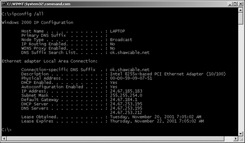
An IPv4 address (which this book refers to as an IP address from now on) is composed of four sets of 8 bits, or octets. The result is that IP addresses are 32 bits in length. Each bit in each octet is assigned a decimal value. The leftmost bit has a value of 128, followed by 64, 32, 16, 8, 4, 2, and 1, left to right.
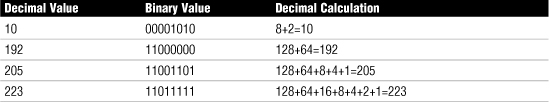
Each bit in the octet can be either a 1 or a 0. This numbering system is called binary. If the value is 1, it is counted as its equivalent decimal value, and if it is 0, it is ignored. If all the bits are 0, the value of the octet is 0. If all the bits in the octet are 1, the value is 255, which is 128+64+32+16+8+4+2+1. Figure 5.2 shows a chart representing the binary-to-decimal conversion. In Figure 5.2, the chart is used to derive the decimal of 195.
Figure 5.2 A binary-to-decimal conversion chart showing how 195 is derived.
By using the set of 8 bits and manipulating the 1s and 0s, any value between 0 and 255 can be obtained for each octet. Table 5.2 shows a few examples of this.
Table 5.2 Examples of Numbers Derived Through Binary
The IP address is composed of four sets of these bits, each of which is separated by a period. For this reason, an IP address is expressed in dotted-decimal notation.
IP addresses are grouped into logical divisions called classes. In the IPv4 address space are five address classes (A through E), although only three are used for assigning addresses to clients. Class D is reserved for multicast addressing, and Class E is reserved for future development.
Of the three classes available for address assignments, each uses a fixed-length subnet mask to define the separation between the network and the node address. A Class A address uses only the first octet to represent the network portion, a Class B address uses two octets, and a Class C address uses three octets. The upshot of this system is that Class A has a small number of network addresses but a large number of possible host addresses. Class B has a larger number of networks but a smaller number of hosts, and Class C has an even larger number of networks, as well as an even smaller number of hosts. The exact numbers are provided in Table 5.3.
Table 5.3 IPv4 Address Classes and the Number of Available Network/Host Addresses
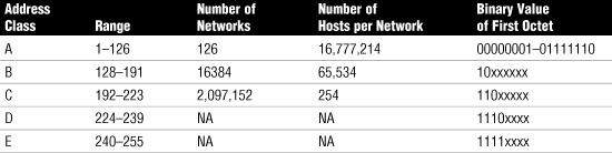
Notice in Table 5.3 that the network number 127 is not included in any of the ranges. The 127 network ID is reserved for the local loopback. The local loopback is a function that is built in to the TCP/IP protocol suite and can be used for troubleshooting purposes.
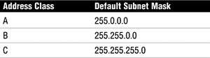
Each of the classes of IP address used for address assignment has a standard subnet mask associated with it. Table 5.4 lists the default subnet masks.
Table 5.4 Default Subnet Masks Associated with IP Address Classes
Exam Alert
Address classes For the Network+ exam, be prepared to identify into which class a given address falls, as well as the default subnet mask for a given class.
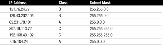
Challenge
In the following table you see six IP addresses. For each line, identify what class the IP address falls into and also provide the default subnet mask for that class. You can compare your answers with the solution table. The first entry is completed as an example.
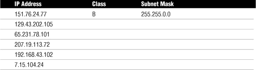
Solution Table
Note
Subnet masks Like an IP address, a subnet mask is a 32-bit address expressed in dotted-decimal format. Unlike an IP address, though, a subnet mask performs just one function: It defines which parts of the IP address refer to the network address and which refer to the node address. For systems to be on the same network, they must have the same subnet mask. Even a 1-bit difference in the subnet mask means that the systems are on different networks.
IPv4 Address Types
The IPv4 has three primary types of address types: unicast, broadcast, and multicast. It is important to be able to distinguish the three types:
• Unicast—With unicast addresses, a single address is specified. Data sent with unicast addressing is delivered to a specific node identified by the address. It is a point-to-point address link.
• Broadcast—At the opposite end of the spectrum of unicast addressing is the broadcast address. A broadcast address is an IP address that you can use to target all systems on a subnet or network instead of single hosts. In other words, a broadcast message goes to everyone on the network.
• Multicast—Multicasting is a mechanism by which groups of network devices can send and receive data between the members of the group at one time, instead of sending messages to each device in the group separately. The multicast grouping is established by each device being configured with the same multicast IP address.
Exam Alert
Address types Before taking the Network+ exam, be sure you can differentiate between unicast, multicast, and broadcast IPv4 addressing.
Distributing IPv4 Addresses to the Network
Having established the need for each system on a TCP/IP-based network to have a unique address, we can now go on to look at how those systems receive their addresses. There are two basic ways in which a system can receive an address—static and dynamic. Microsoft Windows systems also provide an additional feature, called automatic or self-addressing, but in essence this is a variation of dynamic addressing so we will examine it under that heading.
Static Addressing
Static addressing refers to the manual assignment of IP addresses to a system. In other words, a person has to physically configure the system with the correct IP address. There are problems with this approach, most notably that of human error. Configuring one system with the correct address is simple, but in the course of configuring, for instance, a few hundred systems, mistakes are likely. If the IP addresses are entered incorrectly, the system will most likely not be able to connect to other systems on the network. If a client system were misconfigured with the IP address of a server, it could even prevent anyone from connecting to the server, because both systems may disable their network interfaces as a result of the conflict.
Another drawback of static addressing is reconfiguration. If the IP addressing scheme for the organization changes, each system must again be manually reconfigured. In a large organization with hundreds or thousands of systems, such a reconfiguration could take a considerable amount of time and manpower, even if it occurs only infrequently. These drawbacks to static addressing are so significant that nearly all networks use dynamic IP addressing.
Note
Sometimes you need static Some systems such as web servers should always be configured with static IP addresses.
Dynamic Addressing
Dynamic addressing refers to the assignment of IP addresses automatically. On modern networks the mechanism used to do this is the Dynamic Host Configuration Protocol (DHCP). DHCP is a protocol, part of the TCP/IP protocol suite, that allows a central system to provide client systems with IP addresses. Assigning addresses automatically with DHCP alleviates the burden of address configuration and reconfiguration that occurs with static IP addressing. More information on DHCP can be found in Chapter 4, “Understanding the TCP/IP Protocol Suite.”
Bootstrap Protocol (BOOTP)
BOOTP was originally created so that diskless workstations could obtain information—such as the TCP/IP address, subnet mask, and default gateway—needed to connect to the network. Such a system was necessary because diskless workstations had no way of storing the information.
When a system configured to use BOOTP is powered up, it broadcasts for a BOOTP server on the network. If such a server exists, it compares the MAC address of the system issuing the BOOTP request with a database of entries. From this database, it supplies the system with the appropriate information. It can also notify the workstation of a file that it must run on BOOTP.
In the unlikely event that you find yourself using BOOTP, you should be aware that, like DHCP, it is a broadcast-based system. Therefore, routers must be configured to forward BOOTP broadcasts.
APIPA and IPv4
Automatic Private IP addressing (APIPA) is a feature introduced with Windows 98 and included in all subsequent Windows versions. The function of APIPA is that a system can provide itself with an IP address in the event that it is unable to receive an address dynamically from a DHCP server. In such an event, APIPA assigns the system an address from the 169.254.0.0 address range and configures the subnet mask (255.255.0.0). However, it doesn’t configure the system with a default gateway address. As a result, communication is limited to the local network.
Exam Alert
Inability to obtain an address from a DHCP server If a system that does not support APIPA cannot get an address from a DHCP server, the default action is to configure itself with an IP address of 0.0.0.0. Keep this in mind when troubleshooting IP addressing problems on non-APIPA platforms.
The idea behind APIPA is that systems on a segment can communicate with each other in the event of DHCP server failure. In reality, the limited usability of APIPA makes it little more than a measure of last resort. For example, imagine that a system is powered on while the DHCP server is operational and receives an IP address of 192.168.100.2. Then the DHCP server fails. Now if the other systems on the segment are powered on and cannot get an address from the DHCP server because it is down, they would self-assign addresses in the 169.254.0.0 address range via APIPA. The systems with APIPA addresses can talk to each other, but they cannot talk to a system that received an address from the DHCP server. Likewise, any system that received an IP address via DHCP would be unable to talk to systems with APIPA assigned addresses. This, and the absence of a default gateway, is why APIPA is of limited use in real-world environments.
Note
APIPA—smarter than it looks How does APIPA know what address to assign to the system? Before assigning an address, it broadcasts that address on the network. The default action of TCP/IP is to generate an error if it hears from another system with the same address. If APIPA hears this error, it broadcasts another address, and another, from the 169.254.0.0 range until it receives no errors. It then assigns that address to the system. All this occurs invisibly in the background on the computer.
Broadcast Addresses and “This Network”
Two important concepts to keep in mind when working with TCP/IP are broadcast addresses and the addresses used to refer to “this network.” When referring to “this network,” the host ID portion of the address is expressed as 0s. So, for network number 192.168, the reference would be 192.168.0.0. For a Class A network number 12, it would be 12.0.0.0.
Broadcast addresses work much the same way as “this network” addresses, except that the host ID portion of the address is set to 255, to reflect that the message is going to be sent to all the hosts on this network. Using the preceding examples, the broadcast addresses would be 192.168.255.255 and 12.255.255.255.
Classless Interdomain Routing (CIDR)
Classless interdomain routing (CIDR) is a method of assigning addresses outside the standard Class A, B, and C structure. Specifying the number of bits in the subnet mask as a specific number provides more flexibility than with the three standard class definitions.
Using CIDR, addresses are assigned using a value known as the slash. The actual value of the slash depends on how many bits of the subnet mask are used to express the network portion of the address. For example, a subnet mask that uses all 8 bits from the first octet and 4 from the second would be described as /12, or “slash 12.” A subnet mask that uses all the bits from the first three octets would be called /24. Why the slash? In actual addressing terms, the CIDR value is expressed after the address, using a slash. So the address 192.168.2.1/24 means that the IP address of the node is 192.168.2.1, and the subnet mask is 255.255.255.0.
Default Gateways
Default gateways are the means by which a device can access hosts on other networks for which it does not have a specifically configured route. Most workstation configurations default to just using default gateways rather than having any static routes configured. This allows workstations to communicate with other network segments or with other networks, such as the Internet.
Exam Alert
Default gateways For the Network+ exam, you will be expected to identify the purpose and function of a default gateway.
When a system wants to communicate with another device, it first determines whether the host is on the local network or a remote network. If the host is on a remote network, the system looks in the local routing table to determine whether it has an entry for the network on which the remote host resides. If it does, it uses that route. If it does not, the data is sent to the default gateway.
Note
Default gateway must be local Although it might seem obvious, it’s worth mentioning that the default gateway must be on the same network as the nodes that use it.
In essence, the default gateway is simply the path out of the network for a given device. Figure 5.3 shows an example of how a default gateway fits into a network infrastructure.
Figure 5.3 The role of a default gateway.
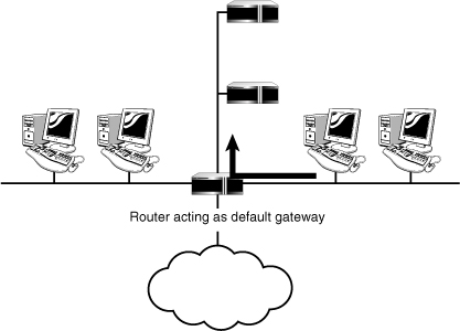
If a system is not configured with any static routes or a default gateway, it is limited to operating on its own network segment.
Understanding Subnetting
Now that we have looked at how IP addresses are used, we can discuss the process of subnetting. Subnetting is a process by which bits from the node portion of an address are used to create more networks than you would have if you used the default subnet mask.
Exam Alert
IP subnetting IP subnetting is a complex task, and it is difficult to explain fully in the space available in this book. The information provided in this section is sufficient to answer any subnetting-related questions you might see on the Network+ exam. In fact, this material goes into more detail than is required. In the real world, subnetting is an important skill.
To illustrate subnetting, let’s use an example. Suppose that you have been assigned the Class B address 150.150.0.0. Using this address and the default subnet mask, you could have a single network (150.150) and can use the rest of the address as node addresses. This would give you many possible node addresses, which in reality is probably not very useful. So you can “borrow” bits from the node portion of the address to use as network addresses. This reduces the number of nodes per network, but chances are, you will still have more than enough.
The simplest use of subnetting in this example would be to use a subnet mask of 255.255.255.0 instead of the default Class B subnet mask of 255.255.0.0. This would give you 254 subnetworks (150.150.1 through 150.150.254.0) and 254 nodes on each of those networks. The only problem arises if you need more than 254 nodes on each network. You then have to use a process referred to as partial-octet or fractional subnetting.
In partial-octet/fractional subnetting, only part of the octet is used to create more networks, and the rest of the octet is still available for assigning as node addresses. Here’s how it works. Using the example of 150.150.0.0, suppose that you want to create six networks. To do that, you need to take enough bits from the third octet to create six network addresses, and at the same time, you need to preserve as many node addresses as possible. If you take the first 3 bits, you can use combinations of the bits to create values as the network addresses. Table 5.5 shows the values.
Table 5.5 Values of Subnets When Using 3 Bits from an Octet

Because no portion of the address can be all 0s or all 1s, you can’t use the 000 and 111 combinations. Therefore, you lose the network assignments of 0 and 224. You are conveniently left with six possible networks.
The bits you are taking are from the left side of the octet. To take this a step further, imagine that you use 5 bits of the octet instead of 3, as in the previous example. Using 5 bits, you would be taking the 128, 64, 32, 16, and 8 binary positions. The network numbers you could use would be 8, 16, 24, 32, 40, 48, 56, 64, and so on up to 248, in multiples of 8, which is the lowest number of the set that was used. In each instance, the available network IDs can be derived by taking the lowest number used, which in the first example is 32 and in this example is 8, and then multiplying up from there.
Note
A little subnet math You can use a calculation to work out how many networks you’ll get from a number of bits. For example, 2 to the power of the number of masked bits minus 2 equals the number of networks, and 2 to the power of the number of unmasked bits minus 2 gives you the number of nodes on the network. You have to subtract 2 from the total in each case because you can’t have a portion of the address as all 1s or all 0s. Here is the actual equation: 2n − 2 = x. Where n is the number of masked bits (or in the case of calculating hosts, the number of unmasked bits).
Let’s look at another example. Imagine that you have been assigned the network ID 211.106.15.0. You need to have at least four networks. What would the subnet mask be, and what are the network IDs that you could use?
The subnet mask would be 255.255.255.224. To create four networks, you would need to use 3 bits (128, 64, and 32). This would give you six possible networks (32, 64, 96, 128, 160, and 192). It’s simple! Remember, as discussed earlier, that you can’t use the values corresponding to all 0s or all 1s when working with subnets, which is why the network numbers 0 and 224 are not included.
The network addresses that can be derived from an address of 211.106.15.0 and a subnet mask of 255.255.255.224 are shown in Table 5.6, along with the usable address ranges for each network.
Table 5.6 Subnetted Network Addresses from the Address 211.106.15.0
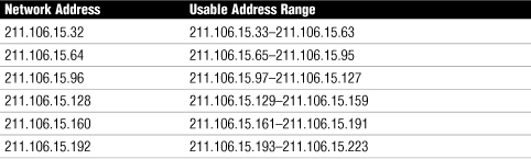
The question often on people’s minds is, “Okay, but how does this work in the real world?” Using the 211.105.15.0 example as a base, let’s look at how the addressing would occur on the client systems. A system with the address 211.106.15.122 would be on the network 211.106.15.96, and the host ID would be 26 (96+26=122). The value of the third octet is the combination of the network address and the host ID.
As you can see, the use of subnetting makes addressing seem more complex, but when you are used to the calculations involved, it’s really straightforward.
There are two main reasons for subnetting. First, it allows you to use IP address ranges more effectively. Second, it provides increased security and manageability to IP networking by providing a mechanism to create multiple networks rather than having just one. Using multiple networks confines traffic to only the network that it needs to be on, which reduces overall network traffic levels. Multiple subnets also create more broadcast domains, which in turn reduces network wide broadcast traffic.
Note
Subnetting help All this subnetting math can get a bit confusing. To get better idea of subnetting, check out the subnetting calculator at www.subnet-calculator.com.
Public and Private IP Address Schemes
IP addressing involves many considerations, not the least important of which are public and private networks. A public network is a network to which anyone can connect. The best and perhaps only pure example of such a network is the Internet. A private network is any network to which access is restricted. A corporate, school, or home network would be considered a private network.
The main difference between public and private networks, apart from the fact that access to a private network is tightly controlled and access to a public network is not, is that the addressing of devices on a public network must be considered carefully, whereas addressing on a private network has a little more latitude.
As you learned in the section “General IP Addressing Principles,” earlier in this chapter, for hosts on a network to communicate by using TCP/IP, they must have unique addresses. The address defines the logical network each host belongs to and the host’s address on that network. On a private internetwork with, for example, three logical networks and 100 nodes on each network, addressing is not a particularly complex task. On a network on the scale of the Internet, however, addressing is more involved.
Each device on the Internet must be assigned a unique address, often referred to as a registered address because it is assigned to a specific party. If two devices have the same address, chances are that neither will be able to communicate. Therefore, the assignment of addresses is carefully controlled by various organizations. Originally, the organization responsible for address assignments was the IANA, but it has since delegated some of the addressing responsibility to other organizations. Around the world, three organizations shoulder the responsibility for assigning IP addresses. In the Americas and parts of the Caribbean, address assignments are the responsibility of the American Registry for Internet Numbers (ARIN); in the Asia Pacific region, it is the Asia Pacific Network Information Centre (APNIC); and in Europe, the Middle East, and parts of Africa, it is Réseaux IP Européens Network Coordination Centre (RIPE NCC). Between them, these organizations ensure that there are no IP address space conflicts and that the assignment of addresses is carefully managed.
Note
IPv4 assignments You can view the IP address range assignments for IPv4 at www.iana.org/assignments/ipv4-address-space.
If you are connecting a system directly to the Internet, you need to get a valid registered IP address from one of these organizations. Alternatively, you can obtain an address from an ISP. Because of the nature of their business, ISPs have large blocks of IP addresses that they can then use to assign to their clients. If you need a registered IP address, getting one from an ISP will almost certainly be a simpler process than going through a regional numbers authority. In fact, getting a number from an ISP is the way most people get addresses. Some ISPs’ plans include blocks of registered IP addresses, working on the principle that businesses are going to want some kind of permanent presence on the Internet. Of course, if you discontinue your service with the ISP, you will no longer be able to use the IP address the ISP provided.
Private Address Ranges
To provide flexibility in addressing, and to prevent an incorrectly configured network from polluting the Internet, certain address ranges are set aside for private use. These address ranges are called private ranges because they are designated for use only on private networks. These addresses are special because Internet routers are configured to ignore any packets they see marked with these addresses. This means that if a network “leaks” onto the Internet, it won’t make it any further than the first router it encounters.
Three private address ranges are defined in RFC 1918, one each from Classes A, B, and C. You can use whichever range you want, although the Class A and Class B address ranges offer more addressing options than does Class C. Table 5.7 defines the address ranges.
Table 5.7 Private Address Ranges
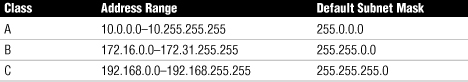
As you can see, the ranges offer a myriad of addressing possibilities. Even the Class C range offers 254 networks, with 254 nodes on each network, which is more than sufficient for the majority of network installations.
Exam Alert
Private address ranges For the Network+ exam, be prepared to identify the benefit of using a private IP address range. They provide a degree of flexibility in addressing without requiring the use of registered IP addresses.
There is no requirement to use private addresses. In fact, many organizations choose not to use them and instead use an addressing scheme of another range. Such a strategy is fine if there is no chance the data from the network will find its way on to a public network. Given that the private ranges are created for this reason and are flexible in terms of accommodating addresses, there is no reason not to use them.
Practical Uses of Public and Private IP Addressing
Having established the purpose of both public and private networks, and of public and private IP addressing, we can now look at how these fit into a practical scenario. It is common practice for a company to have only a handful of registered IP addresses and to configure the internal, private network by using one of the private addressing schemes. Figure 5.4 shows the most basic example.
Figure 5.4 A basic example of public and private network address assignments.
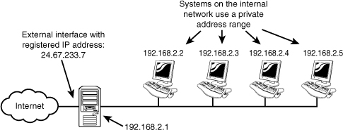
The network in Figure 5.4 could provide Internet access to clients through the proxy server system. The external interface of the proxy server would have a registered IP address, and all the systems on the internal network would use one of the private ranges.
In this example, the external interface of the proxy server could use an ISP-assigned DHCP address. But what if the company wanted to have the same address all the time for a web server or a web access gateway for its email system? Then you would need to consider how you would assign IP addresses to the systems so that they could be accessed by an outside source.
IPv6 Addressing
The current Internet Protocol Version 4 (IPv4) has served as the protocol for the Internet for almost 30 years. When IPv4 was in development 30 years ago, it would have been impossible for its creators to imagine or predict the future demand for IP devices and therefore IP addresses.
Note
Ever wonder about IPv5? IPv5 was an experimental protocol that never went anywhere. Although the protocol IPv5 has fallen into obscurity, the name has been used and we now have IPv6.
As mentioned earlier, IPv4 uses a 32-bit addressing scheme, giving IPv4 a total of 4,294,967,296 possible unique addresses that can be assigned to IP devices. More than 4 billion addresses may sound like a lot, and it is. However, the number of IP enabled devices increases daily at a staggering rate. It is also important to remember that not all these addresses can be used by public networks. Many are reserved for private addresses and are not available for public use. This reduces the number of addresses that can be allocated as public Internet addresses.
The IPv6 project started in the mid 1990s, well before the threat of IPv4 limitations was upon us. Now network hardware and software is equipped and ready to deploy IPv6 addressing. There are a number of improvements with IPv6; most notable is its ability to handle growth for public networks. IPv6 uses a 128-bit addressing scheme, allowing a total number of possible addresses to 340,282,366,920,938,463,463,374,607,431,768,211,456.
This section shows how to identify IPv6 addresses and describes IPv6 address types.
Identifying IPv6 Addresses
As previously discussed, IPv4 uses a dotted-decimal notation, 8 bits converted to its decimal equivalent and separated by periods. An example of an IPv4 address is 192.168.2.1.
Because of the 128-bit structure of the IPv6 addressing scheme, it looks quite a bit different from IPv4 addresses. An IPv6 address is divided along 16-bit boundaries, and each 16-bit block is converted to a 4-digit hexadecimal number and separated by colons. The resulting representation is called colon-hexadecimal. Let’s look at how it works. Figure 5.5 shows an IPv6 address from a Windows Vista system.
Figure 5.5 IPv6 addresses in a Windows Vista dialog screen.
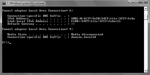
Two IPv6 addresses are listed in Figure 5.5: the link local IPv6 address, which we discuss later, and the external IPv6 address. The external IPv6 address is
2001:0:4137:9e50:3cde:37d1:3f57:fe93
You can simplify an IPv6 address by removing the leading zeros within each 16-bit block. All zeros cannot be removed, however, because each address block must have at least a single digit. The address shown in Figure 5.5 suppresses the zeros. Removing the zero suppression, the address representation becomes
2001:0000:4137:9e50:3cde:37d1:3f57:fe93
Some of the IPv6 addresses you will work with have sequences of zeros. When this occurs the number is often abbreviated to make it easier to read. In the preceding example we saw that a single zero represented a number set in the hexadecimal form. To further simplify the representation of IPv6 addresses, a contiguous sequence of 16-bit blocks set to 0 in the colon hexadecimal format can be compressed to “::”, known as double-colon. For example, you can compress the IPv6 address of 2001:0000:0000:0000:3cde:37d1:3f57:fe93 to 2001::3cde:37d1:3f57:fe93.
However, there are limits to how we can reduce the IPv6 zeros. Zeros within the IPv6 address cannot be eliminated when they are not first in the number sequence. For instance, 2001:4000:0000:0000:0000:0000:0000:0003 cannot be compressed as 2001:4::3. This would actually appear as 2001:4000::3.
When you look at an IPv6 address using a double colon (::), how do you know exactly what numbers are represented? The formula is to subtract the number of blocks from 8 and then multiple the number by 16. So in the address 2001:4000::3, there are three blocks used (2001, 4000, and 3). The equation is
8−3×16=80
Therefore, the total number of bits represented by the double colon in this example is 80.
Exam Alert
Zeros The process of removing zeros can be used only once in an IPv6 address. Using the double colons more than once would make it impossible to determine the number of 0 bits represented by each instance of double colons.
IPv6 Address Types
Another difference between IPv4 and IPv6 is in the address types. IPv4 addressing was discussed earlier in this chapter in the section “IPv4 Addressing.” When it comes to IPv6 addresses, there are several types of addresses:
• Unicast IPv6 addresses—A unicast address specifies a single interface. Data packets sent to a unicast destination travel from the sending host to the destination host. It is a direct line of communication.
• Multicast addresses—As with IPv4 addresses, multicasting sends and receives data between groups of nodes, sending IP messages to that group rather than to every node on the LAN (broadcast) or just one other node (unicast). The prefix used for IPv6 addresses is FF00::/8.
• Anycast addresses—Anycast addresses represent the middle ground between the unicast addresses and multicast addresses. Anycast delivers messages to any one node in the multicast group.
A few types of addresses fall under the unicast banner:
• Global unicast addresses—Global unicast addresses are the equivalent of IPv4 public addresses. These addresses are routable and travel throughout the network. The prefix used for global unicast addresses is 2000::/3.
• Link-local address—Link-local addresses are those addresses designated for use on a single local network. Link-local addresses are automatically configured on all interfaces. This automatic configuration is equivalent to the 169.254.0.0/16 automatically assigned IPv4 addressing. The prefix used for a link-local address is fe80::/10. On a single link IPv6 network with no router, link-local addresses are used to communicate between devices on the link.
• Unique local addresses—Unique local addresses are equivalent to the IPv4 private address space (10.0.0.0/8, 172.16.0.0/12, and 192.168.0.0/16). Like IPv4, where private address ranges are used in private networks, IPv6 uses unique local addresses that will not interfere with global unicast addresses. In addition, routers will not forward unique local traffic outside the site. Unlike link-local addresses, unique local addresses are not automatically configured and must be assigned either through stateless or stateful address configuration processes. The prefix used for the unique local address is (FC00::/7).
Note
Site-local addresses In 2003, RFC 3513 defined the block fec0::/10 as site-local addresses. However, some confusion existed over what “site” meant. The result is that site local addresses were scrapped, and unique local addresses were introduced.
Note
Stateful versus stateless You may come across the terms stateful and stateless configuration. Stateless refers to IP autoconfiguration, where administrators need not manually input configuration information. In a stateful configuration, network devices obtain address information from a server.
Exam Alert
Reserved IPv6 addresses In IPv4, an address (127.0.0.1) is reserved as the loopback address. IPv6 has the same reservation. IPv6 address 0:0:0:0:0:0:0:1 is reserved as the loopback address.
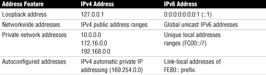
Table 5.8 shows a comparison between IPv4 and IPv6 addressing.
Table 5.8 Comparing IPv4 and IPv6
Exam Alert
Private address For the Network+ exam remember that fe80:: is a private link-local address.
Differentiating Between Routable and Routing Protocols
Routers rely on two types of network protocols to make the routing magic happen: routable protocols and routing protocols. We’ll examine them separately in the next sections.
Routable Protocols
Large internetworks need protocols that allow systems to be identified by the address of the network to which they are attached and by an address that uniquely identifies them on that network. Network protocols that provide both of these features are said to be routable. The most common routable protocol used on today’s network is TCP/IP.
Recall that TCP/IP was developed in the 1970s by the Department of Defense, which needed a protocol to use on its WAN. TCP/IP’s flexibility, durability, and functionality meant that it soon became the WAN protocol of choice and also became the standard for LANs. Today, most networks use TCP/IP in some fashion, even if the main LAN protocol is something other than TCP/IP. TCP/IP is a huge topic, and anyone in networking must understand it.
TCP/IP is a protocol suite composed of numerous individual protocols. Within TCP/IP, the routing protocols used are the Routing Information Protocol (RIP and RIPv2), Open Shortest Path First (OSPF), Intermediate System to Intermediate System (IS-IS), Border Gateway Protocol (BGP), and Enhanced Interior Gateway Routing Protocol (EIGRP). RIP, RIPv2, and BGP are distance-vector routing protocols, and OSPF and IS-IS are link-state routing protocols. You will learn what this means in the next section.
Some routers are capable of routing more than one protocol at a time, a feature known as multiprotocol routing. Multiprotocol routing brings with it a number of considerations, not the least of which is that a multiprotocol router may have to work considerably harder than a router working with only a single protocol. This is the case not only because more than one protocol exists, but because there may also be multiple routing protocols.
Routing Protocols
Routing protocols are the means by which routers communicate with each other. This communication is necessary so that routers can learn the network topology and changes that occur in it. There are two methods to assign routes for the network: static and dynamic routing.
With static routing, network route information must be manually entered by the administrator into a routing table. There are two main disadvantages of this approach: First, manually entering routes is time-consuming and susceptible to human error. Second, if the topology of the network changes, the routers must be manually reconfigured. Therefore, static routing is generally used only in the smallest of environments. In environments with more than a handful of routers, dynamic routing is the preferred option.
Dynamic routing uses routing protocols that are designed to dynamically discover paths to network destinations and how to get to them. Using these routing protocols, the network router must learn the routes available on the network first. The router can then sort through its list of routes and choose the best path for data to follow. The routing protocols can also communicate to other routers, informing them of all discovered routes.
Note
Metrics In routing, the term metric describes the “cost” of a certain route. The metric can be a combination of factors, including the number of routers between a router’s position and the destination, the time it takes to complete the journey, and even a value that can be assigned by an administrator to discourage use of a certain route. Under normal circumstances, routers choose the route with the lowest metric.
The two types of routing protocols are distance-vector and link-state protocols. Each has a different strategy for dealing with router-to-router communication.
Distance-Vector Protocols
With distance-vector routing protocols, each router communicates all the routes it knows about to all other routers to which it is directly attached (that is, its neighbors). Because each router in the network knows only about the routers to which it is attached, it doesn’t know how to complete the entire journey; instead, it only knows how to make the next hop. Hops are the means by which distance-vector routing protocols determine the shortest way to reach a given destination. Each router constitutes one hop; so if a router is four hops away from another router, there are three routers, or hops, between itself and the destination. Distance-vector protocols can also use a time value known as a tick, which enables the router to make a decision about which path is quickest if given the choice of more than one (a common situation on networks with redundant links).
The frequency with which routers send route updates depends on the routing protocol being used, but it is usually between 10 and 60 seconds. At each update, the entire routing table of the sender is sent to the other connected routers. When the other routers receive the information, they check it against the existing information; if there are any changes, they alter their routing tables accordingly.
This constant update cycle is one of the problems of distance-vector routing protocols because it can lead to large amounts of network traffic. Furthermore, after the initial learning period, the updates should (hopefully) be irrelevant; the chances of the network topology changing every 30 seconds or so are slim, and if you do have such a network, some troubleshooting may be in order.
When a change does occur on the network, it may take some time for all the routers to learn of the change. The process of each router learning about the change and updating its routing tables is known as convergence. In a small network, convergence might not take long; but in larger networks, those with, for instance, more than 20 routers, it might take some time to complete. Rather than cause the routers to wait for the updates, you can configure triggered updates, which are sent when a topology change is detected. Using triggered updates can significantly improve the convergence speed of distance-vector–based networks.
You can also use hold-down timers to improve convergence. A hold-down timer prevents a router from trying to make too many changes too quickly. When a router receives a change about a route, it makes the change and then applies a hold-down timer to the change. The hold-down timer prevents further changes from being made to that route within the defined time period. Hold-down timers are particularly useful when an unreliable router keeps going on and off the network. If hold-down timers are not applied, updates to the routing tables on routers would continually be changing, and the network might never converge.
In some configurations, distance-vector routing protocols can lead to routing loops. Routing loops occur when a router tells another router about a route that it heard about from the same router. For example, consider the router layout in Figure 5.6. If Router C becomes unable to access Router D through Network 1, it removes the route from its table and sends the update to Router B; Router B removes the route. But if Router B receives an update from Router A before it sends an update to Router A, the route is reinstated because according to Router A, it can still access Network 1. Now Router B begins to send anything destined for Network 1 back to Router A, which duly sends it back to Router B, and so on, thus creating a routing loop. Each time the route is added to the table, the hop count for the route increases—a problem known as the count to infinity.
Figure 5.6 How routing loops occur.
![]()
You can use two strategies to prevent routing loops when using distance-vector routing protocols:
• Split horizon—The split horizon algorithm addresses the problem of routing loops by not advertising routes back on the interface from which they are learned. In other words, to use Figure 5.6 as an example, Router C would not advertise back to Router B any route that it learned from Router B. Basically, Router C figures that, because it learned about the route from Router B, Router B must be nearer to the destination than it is.
• Split horizon with poison reverse—With this strategy, also known as poison reverse, routers do advertise routes back on the interfaces from which they were learned, but they do so with a hop count of infinity. The value used for infinity (which seems like an impossible situation) depends on the routing protocol being used. Again using the example from Figure 5.6, Router C would advertise to Router B the routes it learned from Router B, but it would also add the infinite hop count. In other words, Router C would say, “I know about Router A, but I can’t reach it myself.” This way, Router B would never try to add the route to Router A through Router C, because according to Router C, it can’t reach Router A.
Several distance-vector protocols are in use today, including the following:
• Routing Information Protocol (RIP)—The RIP protocol is limited to a maximum of 15 hops. One of the downsides of the protocol is that the original specification required router updates to be transmitted every 30 seconds. On smaller networks this can be okay; however, this causes huge traffic on larger networks. The original RIP also did not support router authentication, leaving it vulnerable to attacks.
• RIPv2—This second version of RIP deals with the shortcomings of the original design. RIPv2 includes authentication to allow for secure transmissions and changes from networkwide broadcast discovery using multicast to reduce network traffic. However, to maintain compatibility with RIP, RIPv2 still supports a limit of 15 hops.
• Border Gateway Protocol (BGP)—BGP is a routing protocol often associated with the Internet. BGP can be used between gateway hosts on the Internet. BGP examines the routing table, which contains a list of known routers, the addresses they can reach, and a cost metric associated with the path to each router so that the best available route is chosen. BGP communicates between the routers using the TCP protocol.
• Enhanced Interior Gateway Routing Protocol (EIGRP)—EIGRP is a protocol that lets routers exchange information more efficiently than with earlier network protocols. EIGRP uses its neighbors to help determine routing information. Routers configured to use EIGRP keep copies of its neighbors’ routing information and query these tables to help find the best possible route for transmissions to follow. EIGRP uses the Diffusing-Update Algorithm (DUAL) to determine the best route to a destination.
Link-State Protocols
A router that uses a link-state protocol differs from a router that uses a distance-vector protocol because it builds a map of the entire network and then holds that map in memory. On a network that uses a link-state protocol, routers send out link-state advertisements (LSAs) that contain information about what networks they are connected to. The LSAs are sent to every router on the network, thus enabling the routers to build their network maps.
When the network maps on each router are complete, the routers update each other at a given time, just like a distance-vector protocol does, but the updates occur much less frequently with link-state protocols than with distance-vector protocols. The only other circumstance under which updates are sent is if a change in the topology is detected, at which point the routers use LSAs to detect the change and update their routing tables. This mechanism, combined with the fact that routers hold maps of the entire network, makes convergence on a link-state–based network occur very quickly.
Although it might seem like link-state protocols are an obvious choice over distance-vector protocols, routers on a link-state–based network require more powerful hardware and more RAM than those on a distance-vector–based network. Not only do the routing tables have to be calculated, but they must also be stored. A router that uses distance-vector protocols need only maintain a small database of the routes accessible by the routers to which it is directly connected. A router that uses link-state protocols must maintain a database of the routers in the entire network.
Link-state protocols include the following:
• Open Shortest Path First (OSPF)—OSPF is a link-state routing protocol and is based on the shortest path first (SPF) algorithm to find the least cost path to any destination in the network. In operation, each router using OSPF sends out a list of its neighbors to other routers on the network. From this information, routers can determine the network design and can determine the shortest path for data to travel.
• Intermediate System to Intermediate System (IS-IS)—IS-IS is a link-state protocol that discovers the shortest path for data travel using the SPF algorithm. IS-IS routers distribute topology information to other routers, allowing them to make the best path decisions.
Exam Alert
Identify the protocols Be prepared to identify both the link-state and distance-vector routing protocols used on TCP/IP networks.
Note
Multiprotocol routing In this and the previous section, we discussed routing protocols as they apply to single protocols. But remember that one router may be routing more than one protocol; it may, for example, use OSPF and NLSP.
NAT, PAT, and SNAT
We have had many acronyms in this chapter and we are going to end with three more: Network Address Translation (NAT), Port Address Translation (PAT), and Static Network Address Translation (SNAT).
Network Address Translation (NAT)
The basic principle of NAT is that many computers can “hide” behind a single IP address. The main reason we need to do this is because there simply aren’t enough IP addresses to go around. Using NAT means that only one registered IP address is needed on the external interface of the system acting as the gateway between the internal and external networks.
Note
NAT and proxy servers Don’t confuse NAT with proxy servers. The proxy service is different from NAT, but many proxy server applications do include NAT functionality.
NAT allows you to use whatever addressing scheme you like on your internal networks, although it is common practice to use the private address ranges, which were discussed earlier in the chapter.
When a system is performing NAT service, it funnels the requests given to it to the Internet. To the remote host, the request looks like it is originating from a single address. The system performing the NAT function keeps track of who asked for what and makes sure that when the data is returned, it is directed to the correct system. Servers that provide NAT functionality do so in different ways. For example, it is possible to statically map a specific internal IP address to a specific external one (known as the one-to-one NAT method), so that outgoing requests are always tagged with the same IP address. Alternatively, if you have a group of public IP addresses, you can have the NAT system assign addresses to devices on a first-come, first-served basis. Either way, the basic function of NAT is the same. Figure 5.7 shows a representation of NAT.
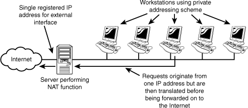
A few variations exist on NAT, each designed for a slightly different purpose. Some of these NAT variations include Port Address Translation (PAT), Static Network Address Translation (SNAT), and Dynamic Network Address Translation (DNAT).
• PAT—NAT allows administrators to conserve public IP addresses and at the same time, secure the internal network. PAT is a variation on NAT. With PAT, all systems on the LAN are translated to the same IP address, but with a different port number assignment. PAT is used when multiple clients want to access the Internet. However, with not enough public IP addresses available, you need to map the inside clients to a single public IP address. When packets come back into the private network, they are routed to their destination with a table within PAT that tracks the public and private port numbers.
• SNAT and DNAT—SNAT maps a private IP address directly to a static unchanging public IP address. This allows an internal system, such as a mail server, to have an unregistered (private) IP address and still be reachable over the Internet. In contrast, in a DNAT configuration, a private IP address is mapped to a public IP address using a pool of public IP addresses.
Summary
This chapter focuses on IP addressing, both for IPv4 and for IPv6. IP addressing is a major topic, and it is important for network administrators to understand it. Of particular importance are the structure of the addresses and the classes in which they fit. Understanding subnetting allows network administrators to use the allocated IP address space in the most efficient way possible.
An important component of configuring TCP/IP addressing on a system is the default gateway. Without a default gateway address, a system can communicate only with other systems on the same subnet.
This chapter also examined the purpose of private and public networks and their role in a TCP/IP network environment. As the IP address space continues to be depleted, such concepts will become increasingly important.
Routing is an important part of network administration. Two types of routing technologies are commonly used, link state and distance vector. Both of these have various protocols associated with them. Link state has IS-IS and OSPF and distance vector uses RIP, RIPv2, BGP, and EIGRP.
A network that uses TCP/IP has a number of services that offer needed functionality. Services such as DHCP and NAT offer a solution to the time-consuming and sometimes problematic task of IP addressing. DNS offers name resolution services that can allow users to access hosts by using easy-to-remember names rather than TCP/IP addressing.
Key Terms
• IPv6
• IPv4
• NAT
• PAT
• SNAT
• DHCP
• Unicast
• OSPF
• IS-IS
• RIP
• RIPv2
• BGP
• EIGRP
• IGP
• EGP
• Next hop
Apply Your Knowledge
Exercises
5.1 Identifying your MAC address
Each and every device on the network has a MAC address imprinted on the NIC. This address is used both to identify machines and as a filter for firewalls. In this exercise, you identify the MAC address of your computer. This exercise assumes you are using a Windows operating system.
Estimated time: 5 minutes
1. Choose Start, Run and in the space provided, type cmd.
2. At the command prompt type ipconfig /all.
3. The command will issue all TCP/IP information on the system and the MAC address.
4. After you see the MAC address listed, identify which parts of the address identify the Organizational Unique Identifier (OUI) and the Universal LAN MAC address. To discover the manufacturer of your network device, try to find them at http://standards.ieee.org/regauth/oui/oui.txt.
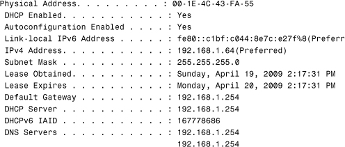
5.2 Discovering your DHCP server address
If you are behind a router at home or using a computer at the office, it is likely you are getting your TCP/IP information from a DHCP server. In this exercise we check the address of the DHCP server. Also, if you are unable to connect to your network, this can also show if you are receiving an address via APIPA.
Estimated time: 5 minutes
1. Choose Start, Run and in the space provided, type cmd.
2. At the command prompt type ipconfig /all.
3. The command will issue all TCP/IP information on the system, including the address of your DHCP server. The printout will look something like the following.
5.3 Releasing and renewing IP information
If you cannot see a valid DHCP server and you have an address in the 169.x.x.x range, you are not on the network and getting your IP information from APIPA. If you get no IP information or a IP address of 0.0.0.0, you have lost all network connectivity and APIPA is likely not configured.
This exercise attempts to release IP information and renew it from a DHCP server. This is a troubleshooting step sometimes done when a DHCP server exists and a system does not recognize it.
Estimated time: 5 minutes
To release an IP address from the command line:
1. Choose Start, Run and in the space provided, type cmd
2. At the command prompt, type ipconfig /all to view current IP information.
3. After you see the IP information, you can release it by typing the following command: ipconfig /release.
4. At the command prompt, type ipconfig /all to see that the IP information has gone.
To renew the IP information from the command line:
1. Choose Start, Run and in the space provided, type cmd to open a command prompt.
2. At the command prompt, type ipconfig /all to view current IP information.
3. After you see the information, you can renew it by typing the following command: ipconfig /renew.
4. At the command prompt, type ipconfig /all to see that the IP information has returned.
Make sure you type a space after ipconfig and a forward slash before release.
After you have released your IP address, you need to renew it by using the command ipconfig /renew. (Again, remember the space after ipconfig and the forward slash before renew.)
Exam Questions
1. Which of the following is a link-state routing protocol used on TCP/IP networks?
![]() A. RIP
A. RIP
![]() B. ARP
B. ARP
![]() C. OSPF
C. OSPF
![]() D. NLSP
D. NLSP
2. You are configuring a firewall to use NAT. In the configuration, you map a private IP address directly to a persistent public IP address. What form of NAT is being used?
![]() A. NAT
A. NAT
![]() B. DNAT
B. DNAT
![]() C. SNAT
C. SNAT
![]() D. All options provided are correct.
D. All options provided are correct.
3. Which of the following statements best describes split horizon?
![]() A. Routes are advertised back on the interface from which they were learned, with a metric of 16.
A. Routes are advertised back on the interface from which they were learned, with a metric of 16.
![]() B. Routes are advertised back on the interface from which they were learned, with a metric of 0.
B. Routes are advertised back on the interface from which they were learned, with a metric of 0.
![]() C. Routes are not advertised back on the interface from which they were learned.
C. Routes are not advertised back on the interface from which they were learned.
![]() D. Routes are advertised back on the interface from which they were learned, with a metric of 16, and on all other interfaces they are advertised back on the interface from which they were learned, with a metric of 0.
D. Routes are advertised back on the interface from which they were learned, with a metric of 16, and on all other interfaces they are advertised back on the interface from which they were learned, with a metric of 0.
4. In a network that uses distance-vector routing protocols, what information is included in the update sent out by each router?
![]() A. Details of the routers that it is directly managed by
A. Details of the routers that it is directly managed by
![]() B. A map of the entire network, with hop counts valued from its current position
B. A map of the entire network, with hop counts valued from its current position
![]() C. Details of all the routers it knows about
C. Details of all the routers it knows about
![]() D. Details of its own configuration
D. Details of its own configuration
5. What condition can arise if routers advertise a route back to the router from which it was learned?
![]() A. Count to infinity
A. Count to infinity
![]() B. Infinity loop
B. Infinity loop
![]() C. Countless hop
C. Countless hop
![]() D. Count to 16
D. Count to 16
6. What term is used by routers to describe each step necessary to reach a destination?
![]() A. Hop
A. Hop
![]() B. Jump
B. Jump
![]() C. Skip
C. Skip
![]() D. Leap
D. Leap
7. Which of the following is a distance-vector routing protocol used on TCP/IP networks?
![]() A. ARP
A. ARP
![]() B. NLSP
B. NLSP
![]() C. OSPF
C. OSPF
![]() D. RIP
D. RIP
8. You decide to move your network from NetBEUI to TCP/IP. For the external interfaces, you decide to obtain registered IP addresses from your ISP, but for the internal network, you choose to configure systems by using one of the private address ranges. Of the following address ranges, which one would you not consider?
![]() A. 192.168.0.0 to 192.168.255.255
A. 192.168.0.0 to 192.168.255.255
![]() B. 131.16.0.0 to 131.16.255.255
B. 131.16.0.0 to 131.16.255.255
![]() C. 10.0.0.0 to 10.255.255.255
C. 10.0.0.0 to 10.255.255.255
![]() D. 172.16.0.0 to 172.31.255.255
D. 172.16.0.0 to 172.31.255.255
9. Which of the following addresses is a Class B address?
![]() A. 129.16.12.200
A. 129.16.12.200
![]() B. 126.15.16.122
B. 126.15.16.122
![]() C. 211.244.212.5
C. 211.244.212.5
![]() D. 193.17.101.27
D. 193.17.101.27
10. Consider the IP address 195.16.17.8. Assuming that the default subnet mask is being used, which part of the address would be considered the network address?
![]() A. 195.16
A. 195.16
![]() B. 195.16.17
B. 195.16.17
![]() C. 16.17.8
C. 16.17.8
![]() D. 17.8
D. 17.8
11. Which of the following protocols is associated with EGP?
![]() A. BGP
A. BGP
![]() B. OSPF
B. OSPF
![]() C. RIPv2
C. RIPv2
![]() D. RIPv1
D. RIPv1
12. Which of the following is the correct broadcast address for the Class A network 14?
![]() A. 14.255.255.0
A. 14.255.255.0
![]() B. 14.0.0.0
B. 14.0.0.0
![]() C. 255.255.255.255
C. 255.255.255.255
![]() D. 14.255.255.255
D. 14.255.255.255
13. What is the IPv6 equivalent of 127.0.0.1? (Select two.)
![]() A. 0:0:0:0:0:0:0:1
A. 0:0:0:0:0:0:0:1
![]() B. 0:0:0:0:0:0:0:24
B. 0:0:0:0:0:0:0:24
![]() C. ::1
C. ::1
![]() D. ::24
D. ::24
14. You ask your ISP to assign a public IP address for the external interface of your Windows 2000 server, which is running a proxy server application. In the email message you get that contains the information, the ISP tells you that you have been assigned the IP address 203.15.226.12/24. When you fill out the subnet mask field on the IP configuration dialog box on your system, what subnet mask should you use?
![]() A. 255.255.255.255
A. 255.255.255.255
![]() B. 255.255.255.0
B. 255.255.255.0
![]() C. 255.255.240.0
C. 255.255.240.0
![]() D. 255.255.255.240
D. 255.255.255.240
15. Which of the following technologies are designed to “hide” behind a single IP address?
![]() A. NAS
A. NAS
![]() B. DHCP
B. DHCP
![]() C. Multicasting
C. Multicasting
![]() D. NAT
D. NAT
16. Which of the following address types are associated with IPv6? (Choose all that apply.)
![]() A. Broadcast
A. Broadcast
![]() B. Multicast
B. Multicast
![]() C. Unicast
C. Unicast
![]() D. Anycast
D. Anycast
17. Which of the following addresses is a valid IPv6 address?
![]() A. 211.16.233.17.12.148.201.226
A. 211.16.233.17.12.148.201.226
![]() B. 42DE:7E55:63F2:21AA:CBD4:D773:CC21:554F
B. 42DE:7E55:63F2:21AA:CBD4:D773:CC21:554F
![]() C. 42DE:7E55:63G2:21AT:CBD4:D773:CC21:554F
C. 42DE:7E55:63G2:21AT:CBD4:D773:CC21:554F
![]() D. 42DE:7E55:63F2:21AA
D. 42DE:7E55:63F2:21AA
18. Which of the address types sends data to all systems on a subnet or network instead of single hosts?
![]() A. Multicast
A. Multicast
![]() B. Unicast
B. Unicast
![]() C. Broadcast
C. Broadcast
![]() D. Anycast
D. Anycast
19. Which of the following IPv6 address types are associated with IPv4 private address ranges?
![]() A. Link-local addresses
A. Link-local addresses
![]() B. Unique local address
B. Unique local address
![]() C. Global address
C. Global address
![]() D. Unicast addresses
D. Unicast addresses
20. Which of the following IPv6 address types are associated with IPv4 automatic 169.254.0.0 addressing?
![]() A. Link-local addresses
A. Link-local addresses
![]() B. Unique local address
B. Unique local address
![]() C. Global address
C. Global address
![]() D. Unicast addresses
D. Unicast addresses
Answers to Exam Questions
1. C. OSPF is a link-state routing protocol used on TCP/IP networks. RIP is a distance-vector routing protocol used on both TCP/IP and IPX/SPX networks; ARP is a component of the TCP/IP protocol suite. NLSP is a link-state routing protocol used on IPX/SPX networks. For more information, see the section “Routable Protocols” in this chapter.
2. C. The term SNAT refers to a configuration whereby a private IP maps address directly to a static unchanging public IP address. Answer B is incorrect because DNAT maps a private IP address to a public IP address using a pool of public IP addresses. The function of NAT is to allow systems to “hide” behind a single IP address. Using NAT means that only one registered IP address is needed on the external interface of the system acting as the gateway between the internal and external networks. For more information, see the section “Network Address Translation (NAT)” in this chapter.
3. C. Split horizon is a routing algorithm that dictates that routes are not advertised back on the interface from which they were learned. Answer A describes the operation of the split horizon with poison reverse algorithm. None of the other answers are valid. For more information, see the section “Routable Protocols” in this chapter.
4. C. In a network that uses distance-vector routing protocols, routers advertise details of the routers they know about. These updates are sent to all the neighbor routers. Answer A describes the actions on a link-state-based network. Answers B and D are invalid. For more information, see the section “Routable Protocols” in this chapter.
5. A. A count to infinity occurs when two routers provide information on the same destination and so create a routing loop. All the other answers are invalid. For more information, see the section “Routable Protocols” in this chapter.
6. A. Each step in the path between a router and its destination is called a hop. The other terms are not used in networking. For more information, see the section “Routable Protocols” in this chapter.
7. D. RIP is a distance-vector routing protocol used on TCP/IP networks. ARP is a component of the TCP/IP protocol suite. NLSP is a link-state routing protocol used on IPX networks, and OSPF is a link-state routing protocol used on TCP/IP networks. For more information, see the section “Routable Protocols” in this chapter.
8. B. The 131.16 range is from the Class B range and is not one of the recognized private IP address ranges. All the other address ranges are valid private IP address ranges. For more information, see the section “Public and Private IP Address Schemes” in this chapter.
9. A. Class B addresses fall into the range 128 to 191. Therefore, Answer A is the only one of the addresses listed that falls into that range. Answer B is a Class A address, and Answers C and D are both Class C IP addresses. For more information, see the section “IPv4 Addressing” in this chapter.
10. B. The address given is a Class C address; therefore, if you are using the default subnet mask, the first three octets represent the network address. None of the other answers are valid. For more information, see the section “IPv4 Addressing” in this chapter.
11. A. External Gateway Protocol specifies routing protocols outside the local LAN. In this case the BGP protocol is an EGP protocol. Internal Gateway protocols include RIP and OSPF. For more information, see the section “Routing Protocols” in this chapter.
12. D. The broadcast address for a network uses the network ID, and all other octets in the address are set to all nodes to indicate that every system should receive the message. Therefore, with a network address of 14, the broadcast address is 14.255.255.255. None of the other answers are valid. For more information, see the section “IPv4 Addressing” in this chapter.
13. A, C. The IPv4 address (127.0.0.1) is reserved as the loopback address; IPv6 has the same reservation. IPv6 addresses 0:0:0:0:0:0:0:1 are reserved as the loopback addresses. The address can also be shown using the :: notation with the zeros removed, ::1. For more information, see the section “IPv6 Address Types” in this chapter.
14. B. In CIDR terminology, the number of bits to be included in the subnet mask is expressed as a slash value. If the slash value is 24, the first three entire octets form the subnet mask, so the value is 255.255.255.0. None of the other answers are correct. For more information, see the section “Classless Interdomain Routing (CIDR)” in this chapter.
15. D. Using NAT, many computers can “hide” behind a single IP address. The main reason we need to do this is because there aren’t enough IPv4 addresses to go around. Using NAT means that only one registered IP address is needed on the external interface of the system acting as the gateway between the internal and external networks. For more information, see the section “NAT, PAT, and SNAT” in this chapter.
16. B, C, D. A key difference between IPv4 and IPv6 is in the address types. When it comes to IPv6 addresses, there are three main types of addresses: unicast, multicast, and anycast addresses. IPv4 uses broadcast addressing, whereas IPv6 doesn’t. For more information, see the section “IPv6 Address Types” in this chapter.
17. B. IPv6 addresses are expressed in hexadecimal format and can therefore use only the letters A through F and numbers. They are also expressed in eight parts. None of the other answers fit these criteria. For more information, see the section “IPv6 Addressing” in this chapter.
18. C. An IPv4 broadcast address is an IP address that you can use to target all systems on a subnet or network instead of single hosts. In other words, a broadcast message goes to everyone on the network. For more information, see the section “IPv4 Address Types” in this chapter.
19. B. Unique local addresses are equivalent to the IPv4 private address space (10.0.0.0/8, 172.16.0.0/12, and 192.168.0.0/16). Like IPv4, where private address ranges are used in private networks, IPv6 uses site-local addresses. Site-local addresses are not automatically configured and must be assigned either through stateless or stateful address configuration processes. The prefix used for the site-local address is (FC00::/7). For more information, see the section “IPv6 Address Types” in this chapter.
20. A. Link-local addresses are automatically configured on all interfaces. This automatic configuration is equivalent to the 169.254.0.0 automatically assigned IPv4 addressing. The prefix used for a link-local address is fe80::. For more information, see the section “IPv6 Address Types” in this chapter.