Chapter Nine
OSI Model
Introduction
One of the most important networking concepts to understand is the Open Systems Interconnection (OSI) reference model. This conceptual model, created by the International Organization for Standardization (ISO) in 1978 and revised in 1984, describes a network architecture that allows data to be passed between computer systems. Even though the OSI model is conceptual, an appreciation of its purpose and function can help you better understand how protocol suites and network architectures work in practical applications.
This chapter takes a detailed look at the OSI model and describes how it relates to real-world networking. It also examines how common network devices relate to the OSI model.
Why Do We Need a Network Model?
Because we are about to spend some of your valuable time discussing a theoretical model, it is only reasonable that we first discuss why we have such a model and how it can help us.
In simple terms, the OSI model provides a structure that helps us work with networks. By relating services and devices to a certain layer of the model, you can get a better idea of their function and purpose. For example, switches use the Media Access Control (MAC) address of the attached devices to make forwarding decisions. In the OSI model, MAC addresses are defined in the MAC sublayer of the data-link layer (Layer 2). If you knew that a bridge was also a data-link layer device, you could reasonably draw the conclusion that it, too, works with MAC addresses—and you would be right. This example is perhaps one of the simplest that we could have used, but it serves the purpose well: It shows how the theoretical model can be translated into actual scenarios.
OSI Reference Model 101
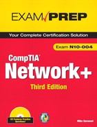
The OSI model consists of seven layers, which is why it is sometimes called the OSI seven-layer model. In diagram form, as shown in Figure 9.1, the model is drawn from bottom to top in the following order: physical, data-link, network, transport, session, presentation, and application layers. The physical layer is classified as Layer 1, and the application layer is classified as Layer 7. In many cases, devices are referred to in relationship to the numbered layers at which they operate. For example, a router is said to be a Layer 3 (network layer) device.
Figure 9.1 The OSI reference model.
Exam Alert
OSI mnemonics Many people find it helps to use a mnemonic device to remember the order of the OSI model. Plenty are available, and they range from the surreal to the obscene. Two that we particularly like are Please Do Not Throw Sausage Pizza Away and All People Seem To Need Data Processing. If you prefer, you can make up your own or even search the Internet to find some of the alternatives. If a mnemonic device helps you remember the model and the appropriate functions at each layer, it is worth using.
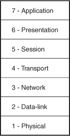
The model is used to relate the transport of data from one host to another. If the data were being sent from an application, such as a web browser, to a web server, it would travel down through all the layers on the sending device, across the network media, and up through all the layers on the receiving device. Figure 9.2 shows a representation of how this works.
Figure 9.2 How data travels between two devices.
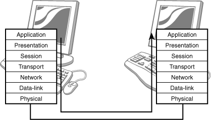
As data is passed up or down through the OSI model structure, headers are added (going down) or removed (going up) at each layer—a process called encapsulation (addition) or decapsulation (removal). Figure 9.3 shows how this works.
Figure 9.3 Encapsulation and decapsulation.
The corresponding layer at the receiving end removes the information added by each device at the sending end. Each layer defines a certain aspect of the communication process, and as data travels up and down the model, the information is sorted into logical groups of bits. The exact term used to refer to the logical group of bits depends on the layer. Table 9.1 contains the terminology used at each layer of the OSI model.
Table 9.1 Terminology Used for Logical Groups of Bits at the Layers of the OSI Model
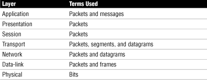
As you can see, at every layer the term packet is used, and in some cases, other terms are used as well. Each layer of the OSI model defines specific functionality. The following sections look at each of the layers separately and discuss the function of each.
Layer 1: The Physical Layer
The physical layer (sometimes referred to incorrectly as the hardware layer) is the layer of the OSI model that defines the physical characteristics of the network. The physical characteristics can include the cable and connector type, the format for pinouts for cables, and so on. It also defines how the data actually travels across the network.
The physical layer also defines the voltage used on the cable and the frequency at which the signals that carry the data are transitioned from one state to another. Such characteristics directly affect the speed of a given media as well as the maximum distance over which a certain media type can be used.
Because the physical layer defines the physical connection to the network, it also defines the physical topology of the network. Recall that there are a number of common physical topologies, including star, ring, bus, mesh, and hybrid, with star being the most common.
Note
OSI numbering Some discussions of the OSI model examine it from top to bottom, and others examine it in reverse. Both methods are valid, but remember that the numbering starts from the bottom and works up. Therefore, it seems most logical to us to explain the model starting at Layer 1 and working up.
Various standards can be partially defined at the physical layer—for example, the Institute of Electrical and Electronics Engineers (IEEE) 802.3 ethernet standard and the 802.5 token ring standard. If you think about it, this is reasonable: An ethernet network card has different physical characteristics than a token ring network card. However, you should know that some of these standards overlap more than one layer of the OSI model. For example, the ethernet standard also defines the media access method, which is a function of the data-link layer.
Layer 2: The Data-Link Layer
The data-link layer is responsible for sending data to the physical layer so that it can be transmitted across the network. The data-link layer can perform checksums and error detection on the data to make sure that the data sent is the same as the data received.
The data-link layer is different from the other layers of the OSI model because it has two distinct sublayers: the Logical Link Control (LLC) sublayer and the Media Access Control (MAC) sublayer. Each has a specific role:
• LLC—The LLC sublayer, which is defined by the IEEE 802.2 standard, controls the access of the media, allowing multiple high-level protocols to use a single network link.
• MAC—The MAC sublayer manages and controls access to the network media for the protocols trying to use it. The MAC address is defined at this sublayer.
As discussed in Chapter 1, “Introduction to Networking,” a difference exists between the physical topology (how a network looks) and the logical topology (how the network works). Whereas the physical layer sees it from a physical topology perspective, the data-link layer sees the network from a logical topology perspective.
Layer 3: The Network Layer
The network layer of the OSI model is primarily concerned with providing a mechanism by which data can be moved between two networks or systems. The network layer does not define how the data is moved; rather, it is concerned with providing the mechanism that can be used for that purpose. The mechanisms that can be used include defining network addressing and conducting route discovery and maintenance. Common network layer protocols include the following:
• IPX—Part of Novell’s IPX/SPX protocol suite, IPX provides a connectionless transport mechanism.
• IP—IP performs much the same function as IPX, but IP is part of TCP/IP protocol suite.
Exam Alert
Connectionless transport Remember, IP is a connectionless transport mechanism that operates at the network layer of the OSI model.
When a system attempts to communicate with another device on the network, network layer protocols attempt to identify that device on the network. When the target system has been identified, it is then necessary to identify the service to be accessed. This is achieved by using a service identifier. On Transmission Control Protocol/Internet Protocol (TCP/IP) networks, service identifiers are commonly referred to as ports, and on Internetwork Packet Exchange/Sequenced Packet Exchange (IPX/SPX) networks they are called sockets, although technically the terms can be used interchangeably.
Switching Methods
An important concept related to the network layer is switching methods. The switching method describes how the data sent from one node reaches another. Three types of switching are used on networks:
• Circuit switching—The best example of circuit switching is a telephone call. The link between caller and receiver is created, after which there is a dedicated communications link between the two points (hence the term circuit). The circuit cannot be broken, which is good because it means that no one else can use the line. In a data communications environment, however, this is a disadvantage because the data often originates from various sources.
• Message switching—In a message-switching environment, transmissions are broken down into messages that can traverse the network by the fastest means available. It might be that all messages travel over the same path, or it might be that messages travel on different paths. At each point in the journey, a node stores the message before it is forwarded to the next hop on the journey. Such a mechanism gives rise to the phrase store and forward. The message-switching system works well in environments in which the amount of data being moved around varies at different times, but it also causes problems such as where to store the data before it is forwarded.
• Packet switching—Although both circuit switching and message switching can get the job done, both have some serious drawbacks that make them unsuitable for use in a modern network environment. Today, most networks use packet switching, which includes the good points of both circuit and message switching and does not include the bad points. In a packet-switched network, data is broken down into packets that can then be transported around the network. Most modern networks use packet switching as the switching method.
Exam Alert
Know the switching methods Be prepared to identify switching methods for the Network+ exam.
A more comprehensive discussion of switching methods, in particular how they relate to wide area networks, is included in Chapter 8, “Wide Area Networking.”
Network Layer Addressing
From a network administrator’s perspective, one of the most important aspects of the network layer is addressing. Network addresses allow a system to be identified on the network by a logically assigned address. This is in contrast to the physically assigned MAC addresses used on the data-link layer. The logical assignment of addresses means that schemes can be created that allow a more hierarchical approach to addressing than MAC addresses provide. By using a hierarchy, it is possible to assign a certain address to logical groups of systems as well as to the systems themselves. The result is that network addressing can be used to create portions of the network called subnets.
Hierarchical addressing systems are possible only with routable network protocols. The most common routable protocol in use today is TCP/IP, although IPX/SPX can still be found on some networks. Other routable protocols, such as AppleTalk, have also lost footing to TCP/IP.
Of course, you don’t have to use a routable protocol. Other nonroutable protocols, such as the rarely seen protocol NetBEUI, can be used, although they are of limited use in today’s modern networking environments, where routable protocols are the order of the day. A more detailed discussion of networking protocols is included in Chapter 4, “Understanding the TCP/IP Protocol Suite.”
Another function of the network layer is route selection, which refers to determining the best path for the data to take throughout the network. Routes can be configured in two ways: statically and dynamically. In a static routing environment, the network administrator must manually add routes to the routing tables. In a dynamic routing environment, routing protocols such as Routing Information Protocol (RIP) and Open Shortest Path First (OSPF) are used. These protocols work by automatically communicating routing information between devices on the network.
Layer 4: The Transport Layer
The basic function of the transport layer is, as its name suggests, to transport data from one host to another. The transport layer handles the actual processing of data between devices. This includes functions such as segmenting data so that it can be sent over the network and then reassembling the segmented data on the receiving end. The transport layer also deals with some of the errors that can occur in a stream of data, such as dropped and duplicated packets. In addition, the transport layer deals with some of the problems that can be produced by the fragmentation and reassembly process performed by the network layer.
The protocols that operate at the transport layer are those directly concerned with the transporting of data across the network. The following are some of the most commonly used transport-layer protocols:
• TCP—Part of the TCP/IP protocol suite, TCP provides a connection-oriented transport mechanism.
• User Datagram Protocol (UDP)—Part of the TCP/IP protocol suite, UDP provides a connectionless transport mechanism.
• SPX—Part of Novell’s IPX/SPX protocol suite, SPX provides a connection-oriented transport mechanism.
Connection-Oriented Protocols
As you can see from the descriptions of the protocols in the preceding section, some are connection oriented and others are connectionless. In a connection-oriented session, the communication dialog between two systems is established, maintained, and then broken when the communication is complete. In technical jargon, this is often referred to as the setting up and tearing down of a session. While we are on the subject of sessions, we should make something clear: The session layer is also responsible for setting up, maintaining, and closing sessions with other hosts, but it does so at the application level rather than the network level. TCP and other transport-layer protocols maintain the sessions at the network level.
Exam Alert
Connection-oriented protocols Connection-oriented protocols can accommodate lost or dropped packets by asking the sending device to retransmit. You should note this for the exam.
Connection-oriented protocols, such as TCP, enable the delivery of data to be guaranteed because the receipt of each packet that is sent must be acknowledged by the receiving system. Any packet not received is re-sent. This makes for a reliable communication system, although the additional steps necessary to guarantee delivery mean that connection-oriented protocols have higher overhead than do connectionless protocols.
Connectionless Protocols
In contrast to connection-oriented communication, connectionless protocols offer only a best-effort delivery mechanism. A connectionless communication is a “fire and forget” mechanism in which data is sent, but no acknowledgments of receipt are sent. This mechanism has a far lower overhead than the connection-oriented method, and it places the onus of ensuring complete delivery on a higher layer, such as the session layer.
Exam Alert
Know the protocols Be prepared to identify both connection-oriented and connectionless protocols on the Network+ exam.
Flow Control
Flow control also occurs at the transport layer. As the name suggests, flow control deals with the acceptance of data. It controls the data flow in such a way that the receiving system can accept the data at an adequate rate. Two methods of flow control are commonly used:
• Buffering—In a buffering system, data is stored in a holding area and waits for the destination device to become available. A system that uses this strategy encounters problems if the sending device can send data much faster than the receiving device can accept it.
• Windowing—Windowing is a more sophisticated approach to flow control than buffering. In a windowing environment, data is sent in groups of segments that require only one acknowledgment. The size of the window (that is, how many segments can be sent for one acknowledgment) is defined at the time the session between the two devices is established. As you can imagine, the need to have only one acknowledgment for every, say, five segments can greatly reduce overhead.
Layer 5: The Session Layer
The session layer is responsible for managing and controlling the synchronization of data between applications on two devices. It does this by establishing, maintaining, and breaking sessions. Whereas the transport layer is responsible for setting up and maintaining the connection between the two devices, the session layer performs much the same function on behalf of the application.
Note
About the OSI layers The Network+ exam touches lightly on the upper layers of the OSI model; therefore, only a basic explanation of them is provided here.
Layer 6: The Presentation Layer
The presentation layer’s basic function is to convert the data intended for or received from the application layer into another format. Such conversion is necessary because the way in which data is formatted so that it can be transported across the network is not necessarily readable by applications. Some common data formats handled by the presentation layer include the following:
• Graphics files—JPEG, TIFF, GIF, and so on are graphics file formats that require the data be formatted in a certain way.
• Text and data—The presentation layer can translate data into different formats such as American Standard Code for Information Interchange (ASCII) and Extended Binary Coded Decimal Interchange Code (EBCDIC).
• Sound/video—MPEGs, QuickTime video, and MIDI files all have their own data formats to and from which data must be converted.
Another important function of the presentation layer is encryption. Encryption is the scrambling of data so that it cannot be read by anything or anyone other than the intended destination. Data encryption is performed at the sending system, and decryption (that is, the unscrambling of data at the receiving end) is performed at the destination. Given the basic role of the presentation layer—that of data format translator—it is the obvious place for encryption and decryption to take place.
Layer 7: The Application Layer
The most common misconception about the application layer, the topmost layer of the OSI model, is that it represents applications used on a system, such as a word processor or a spreadsheet. This is not correct. Instead, the application layer defines the processes that allow applications to use network services. For example, if an application needs to open a file from a network drive, the functionality is provided by components that reside at the application layer.
In simple terms, the function of the application layer is to take requests and data from the user and pass them to the lower layers of the OSI model. Incoming information is passed to the application layer, which then displays the information to the user. Some of the most basic application-layer services include file and print capabilities.
Review Break
OSI Model Summary
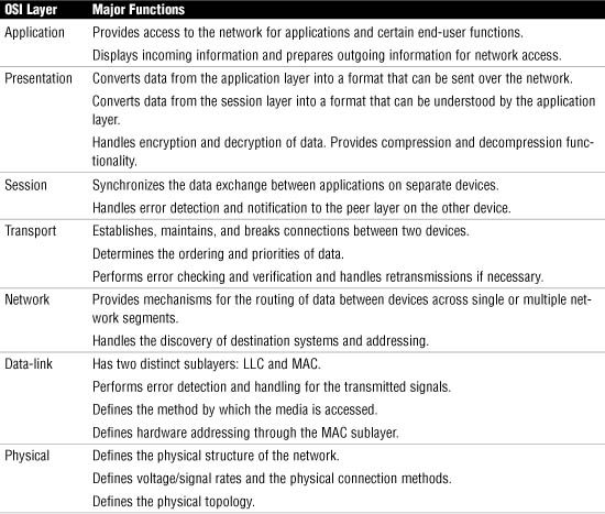
Now that we have discussed the functions of each layer of the OSI model, it’s time for a quick review. Table 9.2 lists the seven layers of the OSI model and describes some of the most significant points of each layer.
Exam Alert
Know Table 9.2 For the Network+ exam, as well as for your real-world experience, the information supplied in Table 9.2 should be sufficient.
The Layers at Which Devices Operate
Now that we have examined the OSI network layer in some detail, we can look at how it relates to the network connectivity devices discussed in Chapter 3: hubs, switches, bridges, routers, and network interface cards (NICs). These devices are said to operate at certain layers of the OSI model based on their functions and roles in the network. Because these devices are covered in Chapter 3, this chapter does not describe them in detail. Instead, this chapter contains a brief description of each device, to jog your memory.
Hubs
Hubs act as the connectivity points of the network on systems that use twisted-pair cabling. There are two types of hubs: active and passive. Each performs the same basic function; they both provide a pathway along which the electrical signals that carry the data can travel. The difference between the two types of hubs is that an active hub has power, and a passive hub does not. Even an active hub does nothing with a signal except regenerate it. Therefore, it is said to be a physical-layer device. Recall that the physical layer deals with placing signals on the media.
Switches
In Chapter 3 you learned that, like hubs, switches act as the connectivity points of the network on systems that use twisted-pair cable. You also learned that a switch offers performance benefits over a hub because it forwards data only to the port on which the destination device is connected. This has the benefit of reducing network traffic because data isn’t forwarded to all the ports on a switch. The switch does this by examining the MAC address of the devices connected to it. The use of the MAC address as an identifier places the switch at Layer 2 of the OSI model. Therefore, it is a data-link layer device.
Note
Layer 3 switches and Layer 4 switches For the Network+ exam, consider switches as Layer 2 devices. In the real world, devices that are called Layer 3 switches and Layer 4 switches are available. These devices “switch” data but do so using other mechanisms.
Bridges
Bridges are used to divide a network into smaller areas through a process known as segmentation. Then, by learning which devices are located on which interface, a bridge can block or forward traffic between the interfaces. It does this by using the MAC address of the attached devices. The use of the MAC address makes a bridge a Layer 2 (that is, data-link layer) device.
Routers
Routers are more complex and more functional than either bridges or switches because they are used to connect networks and then manage the flow of data between the networks. Unlike switches and bridges, routers use software-configured logical network addresses. Because the routing function is implemented at the network layer of the OSI model, routers are referred to as Layer 3 devices.
Note
Brouters A brouter can route data that can be routed or bridge data that cannot be routed. Such a device is said to be both a Layer 2 device and a Layer 3 device.
NICs
A NIC provides the physical connectivity point to the network for a computer system. Although NICs are physical components, they are defined as data-link layer devices because they are used in physical media access (which is handled at the MAC sublayer) and the logical access of the network media (which is handled at the LLC sublayer).
Note
There is some debate as to whether a NIC is in fact just a Layer 2 device, or whether it is both a Layer 1 and Layer 2 device. This debate occurs because although it provides addressing and media access functions (Layer 2 roles), it is also responsible for placing the signal on the network media, which is a Layer 1 task. For the purposes of the Network+ exam, CompTIA considers the NIC to be just a Layer 2 device, which is why we have classified it as such here.
Wireless Access Points (APs)
Wireless access points (APs) are devices that provide connectivity between wireless portions of a network and wired portions of a network. APs are considered data-link layer devices because their primary function is to provide connectivity to the network. This connectivity is independent of the network communications protocol. Like a NIC, APs are involved in both the physical access of the network (which is handled at the MAC sublayer) and the logical access of the network (which is handled at the LLC sublayer).
Review Break
Summary of the Layers at Which Devices Operate
Table 9.3 summarizes the devices discussed in the previous sections and the corresponding layers at which they operate.
Table 9.3 The OSI Model Layers at Which Various Devices Operate

Exam Alert
Know where a device operates In the Network+ exam you might be asked to identify the layer at which a given device operates.
TCP/IP Protocol Suite Summary
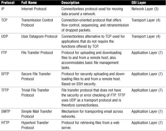
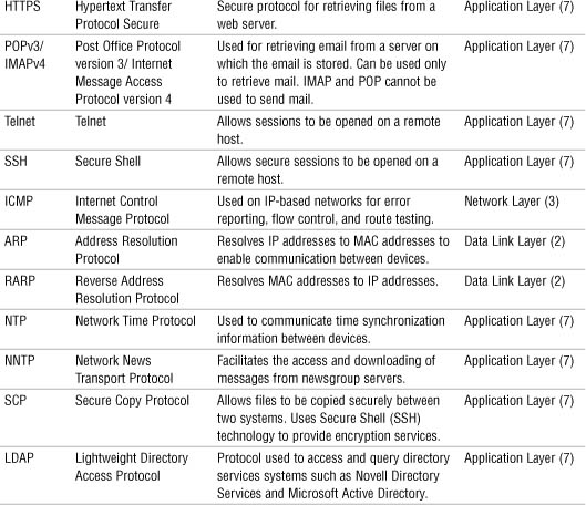
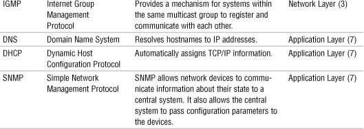
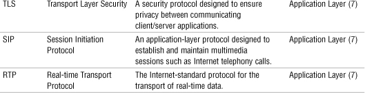
Chapter 4 reviewed the various protocols found within the TCP/IP protocol suite. Each of these protocols maps to the OSI model. Knowing what the protocol does helps to identify where it fits within the OSI model. Table 9.4 summarizes the details of each of the various TCP/IP protocols and where they fit into the OSI model. You can use this table for review before you take the Network+ exam.
Table 9.4 TCP/IP Protocol Suite Summary
Exam Alert
Protocols and OSI For the Network+ exam, be sure you are able to identify the OSI layer that a particular protocol operates at. Review the information provided in Table 9.4.
Summary
The OSI model is a conceptual model that defines seven layers. Each of these layers performs a specific function that plays an important part in the end-to-end communication between two devices. The model allows us to relate the function of a certain protocol or service to a specific function of the model. For example, IP is responsible for the discovery and establishment of routes through the network. Therefore, it is reasonable to assume that IP is a network-layer protocol because such functions are performed at the network layer. The ability to draw parallels like this can be a useful aid to understanding networking from both conceptual and practical levels.
Because the OSI model defines the functions performed at various layers, it can be said that network devices operate at certain layers of the OSI model. The layer at which a device operates is defined by the function of the device and the information the device uses to complete its task. Of the commonly used network devices, hubs operate at the physical layer; network cards, bridges, and switches operate at the data-link layer; and routers operate at the network layer.
Understanding the OSI model is important for networking. Even though it can sometimes be difficult to see how the OSI model is relevant in day-to-day tasks, it helps to reinforce networking theory and provides a framework in which to work.
Key Terms
• Connection-oriented protocols
• LLC
• MAC
• OSI
• SPX
• TCP
• UDP
Apply Your Knowledge
Exercise
9.1 Identifying OSI layers
For the Network+ exam, you will need to be able to identify the various layers of the OSI model and the network devices that correspond to each level. With that in mind, in lieu of a hands-on project, this chapter provides a practical exercise to reinforce the concepts discussed in this chapter. Your ability to correctly complete this exercise will show sufficient knowledge of the OSI model.
Estimated time: 10 minutes
1. Refer to the worksheet in Figure 9.4 and identify two functions for each layer of the OSI model.
Figure 9.4 A hands-on OSI model project.
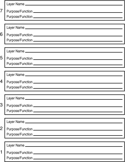
2. Check your responses against the information in Table 9.2.
Exam Questions
1. At which layer of the OSI model does a switch operate?
![]() A. Physical
A. Physical
![]() B. Data-link
B. Data-link
![]() C. Network
C. Network
![]() D. Session
D. Session
2. Which of the following devices operate at Layer 2 of the OSI model? (Choose all that apply.)
![]() A. Switch
A. Switch
![]() B. Network card
B. Network card
![]() C. Hub
C. Hub
![]() D. Bridge
D. Bridge
3. Which layer of the OSI model is responsible for synchronizing the exchange of data between two devices at the application level?
![]() A. Transport
A. Transport
![]() B. Session
B. Session
![]() C. Presentation
C. Presentation
![]() D. Data-link
D. Data-link
4. Which of the following transport-layer protocols offer guaranteed delivery? (Choose the two best answers.)
![]() A. SPX
A. SPX
![]() B. UDP
B. UDP
![]() C. IPX
C. IPX
![]() D. TCP
D. TCP
5. Which layer of the OSI model is responsible for route discovery?
![]() A. Session
A. Session
![]() B. Data-link
B. Data-link
![]() C. Network
C. Network
![]() D. Transport
D. Transport
6. What are the two sublayers of the data-link layer?
![]() A. Logical link control
A. Logical link control
![]() B. Logical loop control
B. Logical loop control
![]() C. Media access control
C. Media access control
![]() D. Multiple access control
D. Multiple access control
7. Which of the following are responsibilities of the transport layer? (Choose the two best answers.)
![]() A. Performs error detection and handling for the transmitted signals
A. Performs error detection and handling for the transmitted signals
![]() B. Synchronizes data exchange between two applications
B. Synchronizes data exchange between two applications
![]() C. Performs error checking and verification
C. Performs error checking and verification
![]() D. Establishes, maintains, and breaks connections between devices
D. Establishes, maintains, and breaks connections between devices
8. Which layer of the OSI model defines the method by which the network media are accessed on a logical level?
![]() A. Data-link
A. Data-link
![]() B. Physical
B. Physical
![]() C. Session
C. Session
![]() D. Presentation
D. Presentation
9. At which layer of the OSI model does a hub operate?
![]() A. Application
A. Application
![]() B. Network
B. Network
![]() C. Physical
C. Physical
![]() D. Data-link
D. Data-link
10. Which of the following terms is not used to describe a logical grouping of bits?
![]() A. Datagram
A. Datagram
![]() B. Segment
B. Segment
![]() C. Package
C. Package
![]() D. Packet
D. Packet
11. Which layer of the OSI model defines the signal rates and voltages that are used?
![]() A. Data-link
A. Data-link
![]() B. Physical
B. Physical
![]() C. Session
C. Session
![]() D. Presentation
D. Presentation
12. At which layer of the OSI model does a WAP operate?
![]() A. Physical
A. Physical
![]() B. Data-link
B. Data-link
![]() C. Network
C. Network
![]() D. Transport
D. Transport
13. At which layer of the OSI model does a NIC operate?
![]() A. Physical
A. Physical
![]() B. Data-link
B. Data-link
![]() C. Network
C. Network
![]() D. Transport
D. Transport
14. At which layer of the OSI model do encryption and decryption take place?
![]() A. Physical
A. Physical
![]() B. Session
B. Session
![]() C. Application
C. Application
![]() D. Presentation
D. Presentation
15. Which of the following are commonly used flow control strategies? (Choose the two best answers.)
![]() A. Buffering
A. Buffering
![]() B. Segmentation
B. Segmentation
![]() C. Windowing
C. Windowing
![]() D. Direct flow management
D. Direct flow management
16. You have been called in to troubleshoot a 10Base2 network that is experiencing problems. After performing some tests, you determine that the problem lies with one of the terminators on the network. At which layer of the OSI model does the problem exist?
![]() A. Physical
A. Physical
![]() B. Data-link
B. Data-link
![]() C. Network
C. Network
![]() D. Session
D. Session
17. Which of the following OSI layers is responsible for establishing connections between two devices?
![]() A. Session
A. Session
![]() B. Network
B. Network
![]() C. Transport
C. Transport
![]() D. Application
D. Application
18. At which layer do the protocols that handle route discovery reside?
![]() A. Transport
A. Transport
![]() B. Network
B. Network
![]() C. Session
C. Session
![]() D. Application
D. Application
19. At the transport layer, two types of protocols are used for sending data to a remote system. What terms are used to describe these protocols? (Choose the two best answers.)
![]() A. Connection oriented
A. Connection oriented
![]() B. Connection reliant
B. Connection reliant
![]() C. Connection dependent
C. Connection dependent
![]() D. Connectionless
D. Connectionless
20. At which layer of the OSI model does a router operate?
![]() A. Application
A. Application
![]() B. Session
B. Session
![]() C. Network
C. Network
![]() D. Transport
D. Transport
Answers to Exam Questions
1. B. A switch uses the MAC addresses of connected devices to make forwarding decisions and therefore operates at the data-link layer of the OSI model. Components at the physical layer define the actual connection to the network. Physical layer components include cabling and connectors. Protocols at the network layer handle addressing and route discovery. Protocols at the session layer deal with establishment and termination between systems or applications on the network. None of the other answers apply. For more information, see the section “The Layers at Which Devices Operate” in this chapter.
2. A, B, D. Switches, bridges, and NICs operate at the data-link layer of the OSI model, which is also known as Layer 2. A hub is defined as a physical layer (that is, Layer 1) device. For more information, see the section “The Layers at Which Devices Operate” in this chapter.
3. B. The synchronization of data between applications is performed at the session layer of the OSI model. Protocols at the transport layer establish, maintain, and break connections between two devices. Protocols at the presentation layer convert data so that it can be received from or sent to the network. Devices at the data-link layer define the media access method and hardware addressing. For more information, see the section “OSI Reference Model 101” in this chapter.
4. A, D. Both SPX and TCP are connection-oriented protocols that offer guaranteed delivery of data. UDP and IPX are both connectionless protocols. For more information, see the section “OSI Reference Model 101” in this chapter.
5. C. Route discovery is performed by protocols that operate at the network layer of the OSI model. Devices at the data-link layer define the media access method and hardware addressing. Protocols at the network layer handle addressing and route discovery. Protocols at the transport layer establish, maintain, and break connections between two devices. For more information, see the section “OSI Reference Model 101” in this chapter.
6. A, C. The data-link layer of the OSI model is divided into two distinct sublayers: the LLC sublayer and the MAC sublayer. None of the other answers are valid. For more information, see the section “OSI Reference Model 101” in this chapter.
7. C, D. The network layer is responsible for, among other things, performing error checking and verification, and establishing, maintaining, and breaking connections between devices. Synchronizing data exchange between applications occurs at the session layer. Error detection and handling for the transmitted signals occur at the data-link layer. For more information, see the section “OSI Reference Model 101” in this chapter.
8. A. Standards at the data-link layer define how the network is accessed on a logical level. Do not confuse the function of the data-link layer with that of the physical layer, which performs similar functions but at a physical rather than a logical level. The session layer handles the synchronization of data between applications on networked devices. Protocols at the presentation layer prepare data for transmission on the network or prepare data from the network to be passed to the application layer. For more information, see the section “OSI Reference Model 101” in this chapter.
9. C. A hub operates at the physical layer of the OSI model. Components at the application layer are software based. A router is an example of a network layer device. A switch is an example of a data-link layer device. For more information, see the section “The Layers at Which Devices Operate” in this chapter.
10. C. The term package is not valid when referring to a logical grouping of bits. All the other answers are valid terms. For more information, see the section “OSI Reference Model 101” in this chapter.
11. B. The physical layer of the OSI model defines the physical characteristics of the network, including voltages and signaling rates. The data-link layer performs error detection and handling for transmitted signals. It also defines the method by which the media is accessed. The session layer handles the synchronization of data between applications on networked devices. Protocols at the presentation layer prepare data for transmission on the network or prepare data from the network to be passed to the application layer. For more information, see the section “OSI Reference Model 101” in this chapter.
12. B. WAPs provide connectivity between wireless and wired portions of a network. They are classified as data-link layer devices because they provide logical connectivity but are protocol independent. Components at the physical layer define the actual connection to the network. Physical layer components include cabling and connectors. A router is an example of a network layer device. Protocols at the transport layer establish, maintain, and break connections between two devices. For more information, see the section “The Layers at Which Devices Operate” in this chapter.
13. B. NICs operate at the data-link layer of the OSI model. Physical layer components include cabling and connectors. A router is an example of a network layer device. Transport layer components are typically software. For more information, see the section “The Layers at Which Devices Operate” in this chapter.
14. D. Encryption is a function that takes place at the presentation layer of the OSI model. Components at the physical layer define the actual connection to the network. Physical layer components include cabling and connectors. The session layer handles the synchronization of data between applications on networked devices. Protocols at the presentation layer prepare data for transmission on the network or prepare data from the network to be passed to the application layer. For more information, see the section “OSI Reference Model 101” in this chapter.
15. A, C. Windowing and buffering are commonly used flow control strategies. Segmentation is the term used to describe the division of packets to enable them to be transported across the network. Answer d is not valid. For more information, see the section “OSI Reference Model 101” in this chapter.
16. A. Cable and connectors are physical elements of the network, so they relate to the physical layer of the OSI model. The data-link layer performs error detection and handling for transmitted signals. It also defines the method by which the media is accessed. Protocols at the network layer handle addressing and route discovery. The session layer handles the synchronization of data between applications on networked devices. For more information, see the section “The Layers at Which Devices Operate” in this chapter.
17. C. The transport layer is responsible for establishing connections between two devices. The session layer handles the synchronization of data between applications on networked devices. Protocols at the network layer handle addressing and route discovery. The application layer provides access to the network for applications and certain end-user functions. For more information, see the section “OSI Reference Model 101” in this chapter.
18. B. Protocols at the network layer are responsible for route discovery. Protocols at the transport layer establish, maintain, and break connections between two devices. The session layer handles the synchronization of data between applications on networked devices. Protocols at the application layer provide access to network functions. For more information, see the section “OSI Reference Model 101” in this chapter.
19. A, D. The two terms used to describe protocols at the transport layer are connection oriented and connectionless. The terms in Answers B and C are not used. For more information, see the section “OSI Reference Model 101” in this chapter.
20. C. A router uses the logical network address to make decisions and is therefore a network layer device. Application, session, and transport level components are software based. For more information, see the section “The Layers at Which Devices Operate” in this chapter.