Chapter Eight
Wide Area Networking
Introduction
In the beginning, there was a single computer. Soon it connected to other computers and became a local area network (LAN). LANs allowed files, printers, and applications to be shared freely and securely throughout an organization. For a short time, a LAN was sufficient in many organizations, but the need arose to interconnect LANs to provide enterprisewide data availability.
As you might imagine, connecting LANs provided a challenge primarily because of the distances separating them. Some were across town, and some were thousands of miles apart—a long way to run a segment of coaxial cable. Technologies such as X.25 were introduced that could span these distances, and the wide area network (WAN) was born. Some technologies used by WANs are different from those used by LANs; essentially, WANs use different wires and different protocols. In addition, WANs can be far more complex to implement. As far as functionality is concerned, a WAN does exactly what a LAN does: It provides connectivity between computers.
Exam Alert
Be familiar with WAN The Network+ exam covers a number of WAN technologies. Often the exam stays away from asking questions related to maximum speeds of a WAN technology because these tend to change quickly.
Introducing Wide Area Networking
To implement a WAN, you need a way to connect two geographically separated networks. Depending on the financial resources of an organization, a WAN can use a dedicated link between networks to establish communication. Or, the WAN can be created using a larger public network such as the Internet. Before looking at the various WAN technologies available, we’ll start our examination of WANs by looking at perhaps the most significant consideration facing anyone who is implementing a WAN: whether to use a public or a private network as a means of connectivity. The private and public WAN network services each have their advantages and disadvantages, and knowing the difference between them is a good place to start.
Public Networks
The bottom line for many decisions made in networking is money. This is often true when choosing a WAN networking method. To save money and a certain amount of administrative effort, you can choose to set up a WAN using an existing transmission infrastructure. Two key public networks can be used to establish a WAN: the public switched telephone network (PSTN) and the Internet. Each of these is discussed in the following sections.
Public Switched Telephone Network (PSTN)
The Public Switched Telephone Network (PSTN), often called plain old telephone system (POTS), is the entire collection of interconnected telephone wires throughout the world. Elements of the PSTN include all the equipment that goes into connecting two points, such as the cable, the networking equipment, and the telephone exchanges.
Note
More POTS A detailed discussion of POTS is included later in this chapter.
Exam Alert
Use PSTN to save money If financial cost is a major concern, PSTN is the method of choice for creating a WAN.
The modern PSTN is largely digital, with analog connections existing primarily between homes and the local phone exchanges. Modems are used to convert the computer system’s digital signals to analog so that they can be sent out over the analog connection.
Using the PSTN to establish WAN connections has been a popular choice, although the significant drawback is the limited transfer speeds. Transfer on the PSTN is limited to 56Kbps with a regular modem. Today’s high-speed networks using videoconferencing, VoIP, large data transfers, and more cannot manage with these limited speeds. Newer WAN technologies have pushed PSTN into the background. However, PSTN is still used by companies that need to send only small amounts of data remotely or have a very limited budget. PSTN remains an inexpensive alternative for remote access.
The Internet
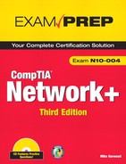
The Internet is a popular method for establishing WAN connections. Using the Internet to provide remote access creates a cost-effective and reliable solution for interconnecting LANs. One of the most common methods of using the Internet for connecting LANs is through the use of virtual private networks (VPN). Essentially, a VPN uses a public network, such as the Internet, to create a communication tunnel between two end points. Unlike private networks, VPNs can be used on an as-needed basis. A connection can be established to a remote location and then dropped when no transmissions are required. Many organizations use VPNs as dedicated links that permanently connect private LANs. The security available for VPNs further makes them an attractive option. Figure 8.1 shows a VPN connection over a public network.
Figure 8.1 A VPN connecting two private LANs.
Exam Alert
Cable and DSL The availability of cable Internet access and Digital Subscriber Line (DSL) services means that companies are able to use these technologies as a means to establish VPN connections. Cable and DSL are particularly well suited for such a purpose because they offer high speeds at a low cost. They are also available 24/7 for an inclusive cost, which is a bonus over other methods such as ISDN, which may be billed on a usage basis. Cable and DSL, in concert with VPNs, are making it possible for companies to establish low-cost, secure WAN links. Previously, many companies would not have been able to afford a solution that offers this kind of speed, availability, and security.
Public Networks: Advantages and Disadvantages
The biggest advantages of a public network, such as the PSTN and the Internet, are accessibility and availability. Public network access is almost everywhere, and perhaps more importantly, it is inexpensive. In addition, the technologies required to use public networks, such as VPNs, are typically easy to configure and can be implemented in a short amount of time. All major client operating systems ship with the software necessary to create a VPN.
You are most likely to see public networks being utilized by small organizations, where the money for a private network is simply not available or needed. For many small organizations, the capabilities that the Internet provides are sufficient.
As you might have already surmised, some drawbacks exist in using a public network to interconnect LANs. First and foremost is security. When you establish a link over a public network, there is a risk that another user on that network may compromise your data. Technologies such as VPNs put a lot of emphasis on security measures such as encryption and authentication that are aimed at reducing the security risk. Commonly a security protocol called IPsec is used on the connection to ensure that data sent over the link is encrypted and that strict authentication requirements are met. However, if you are sending sensitive data over a public network, there is always a risk. Discussions about the degree of risk are best left to hackers, crackers, and security experts, and that debate is sure to go on for a long time.
In addition to the security risks, numerous other considerations exist concerning public lines, such as disconnections, logon troubles for modems, Internet failures, and a host of other likely and unlikely circumstances. Keep in mind that with a public network you are getting something for nothing—or at least for very little—and you will have to make concessions. If you can’t live with the drawbacks, you can always switch to a private network.
Private Networks
If we all had unlimited IT budgets, most of us would be using private networking to connect LANs. Private networks provide a solid way to maintain connectivity between LANs, at least for those who can afford them.
A private network does not suffer from the same considerations of a public network. Many technologies are used to create private networks, and they vary in cost and implementation difficulty. The specific technologies used to create WANs over private networks are discussed in detail in this chapter in the “WAN Technologies” section.
A private network can be designed and implemented from scratch based on an organization’s specific needs. The network can be as complex or simple, expensive or inexpensive, secure or insecure as allowed by the budget, location, utilization, and data usage demands. The network can also be designed around the security needs of the data being carried over the network. For instance, fiber-based networks are more secure and more expensive than copper-based networks or wireless networks. A private network can employ various protocols based on security or performance needs. Basically, a private network gives the designer an opportunity to correct most of the problems and drawbacks associated with public networks.
Probably the biggest single disadvantage of a private network is the cost. Whereas the PSTN is yours for the asking at a nominal monthly fee, a private network requires that you purchase or lease every piece of cable, all the network cards, hubs, routers, switches, and so on, until you have enough equipment to go live.
Because of the required networking equipment, private networks often require more administrative effort than public networks, where the networking infrastructure is maintained by outside administrators. Often, a hidden cost associated with private networks is the need for qualified people to manage and maintain them. As the network grows—and it will—it becomes increasingly complex and requires more attention. Good administration is a must; otherwise, inefficiencies and lack of dependability will quickly consume the value of the private network. A company needs to carefully weigh administrative issues before getting into private networking.
Using a private WAN need not be a total do-it-yourself approach. In fact, most telephone companies provide managed WAN services, which include all the equipment you need to create a WAN. They also monitor and manage the connection for you, making sure that everything operates as it is supposed to. There is, of course, a price attached to such a service, but for many companies, a managed solution is money well spent.
Switching Methods
Before we go on to discuss the specific WAN technologies, we must first look at the switching methods. For systems to communicate on a network, there has to be a communication path between them on which the data can travel. To communicate with another entity, you need to establish a path that can be used to move the information from one location to another and back. This is the function of switching: It provides a path between two communication end points and routes the data to make sure that it follows the correct path. Three types of switching are used most often in networks today:
Exam Alert
Know the differences For the Network+ exam, you will be expected to identify the differences between the various switching methods.
Packet Switching
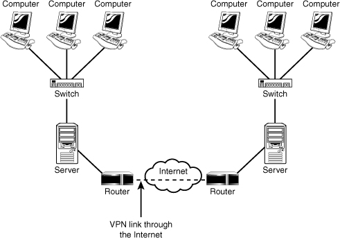
In packet switching, messages are broken into smaller pieces called packets. Each packet is assigned source, destination, and intermediate node addresses. Packets are required to have this information because they do not always use the same path or route to get to their intended destination. Referred to as independent routing, this is one of the advantages of packet switching. Independent routing allows for a better use of available bandwidth by letting packets travel different routes to avoid high-traffic areas. Independent routing also allows packets to take an alternate route if a particular route is unavailable for some reason. Figure 8.2 shows how packets can travel in a packet-switching environment.
Figure 8.2 An example of packet switching.

Exam Alert
Packet switching Packet switching is the most popular switching method for networks and is used on most LANs.
In a packet-switching system, when packets are sent onto the network, the sending device is responsible for choosing the best path for the packet. This path might change in transit, and it is possible for the receiving device to receive the packets in a random or nonsequential order. When this happens, the receiving device waits until all the data packets are received, and then it reconstructs them according to their built-in sequence numbers.
Note
Packet size restrictions The packet size is restricted in a packet-switching network to ensure that the packets can be stored in RAM instead of on a hard disk. The benefit of this size restriction is faster access because retrieving data from RAM is faster than retrieving data from a hard disk.
Two types of packet-switching methods are used on networks: virtual-circuit packet switching and datagram packet switching. Each of these methods is described in the following sections.
Virtual-Circuit Packet Switching
When virtual-circuit switching is used, a logical connection is established between the source and the destination device. This logical connection is established when the sending device initiates a conversation with the receiving device. The logical communication path between the two devices can remain active for as long as the two devices are available or can be used to send packets once. After the sending process has completed, the line can be closed. There are two types of virtual circuit switching methods, permanent virtual circuits (PVC) and switched virtual circuits (SVC).
• Permanent Virtual Circuit (PVC)—A PVC is a permanent dedicated virtual link between the sending and receiving device. The PVC can be used to replace a hardwired dedicated end-to-end line.
• Switched Virtual Circuit (SVC)—An SVC represents a temporary virtual circuit that is established and maintained only for the duration of a data transfer session. The virtual circuit is cleared after the data transfer is completed.
Datagram Packet Switching
Unlike virtual-circuit packet switching, datagram packet switching does not establish a logical connection between the sending and transmitting devices. The packets in datagram packet switching are independently sent, meaning that they can take different paths through the network to reach their intended destination. To do this, each packet must be individually addressed, to determine where its source and destination are. This method ensures that packets take the easiest possible routes to their destination and avoid high-traffic areas.
Because in datagram packet switching the packets can take multiple paths to reach their destination, they can be received in a nonsequential order. The information contained within each packet header is used to reconstruct all the packets and ensure that the original message is received in total.
Datagram packet switching technologies are fault tolerant. As mentioned previously, on a packet switched network, a large message is broken into smaller packets which travel through various paths to reassemble at the destination. These packets travel independently of each other and can take different routes to get to the destination. These multiple routes for packets to travel create fault tolerance, if one path becomes unavailable; there is another way for the packets to get to travel.
Datagram packet switching networks are considered connectionless, meaning that they do not require a dedicated active connection for the packets to reach their destination. In a connectionless method, the communications link isn’t established between sender and recipient before packets can be transmitted. Connectionless switching use various routes and allow multiple network users to use the circuits simultaneously.
This is in contrast to virtual packet switching, a connection-oriented method in which the communications link is made before any packets are transmitted. Because the link is established before transmission begins, the packets that constitute a message all follow the same route to their destination.
Note
Datagram packet sizes The data packet size used with datagram packet switching is kept small in case of error, which would cause the packets to be re-sent.
Circuit Switching
In contrast to the packet-switching method, circuit switching requires a dedicated physical connection between the sending and receiving devices. The most commonly used analogy to represent circuit switching is a telephone conversation, in which the parties involved have a dedicated link between them for the duration of the conversation. When either party disconnects, the circuit is broken, and the data path is lost. This is an accurate representation of how circuit switching works with network and data transmissions. The sending system establishes a physical connection, the data is transmitted between the two, and when the transmission is complete, the channel is closed.
Some clear advantages to the circuit-switching technology make it well suited for certain applications. The primary advantage is that after a connection is established, a consistent and reliable connection exists between the sending and receiving device. This allows for transmissions at a guaranteed rate of transfer.
Like all technologies, circuit switching has downsides. As you might imagine, a dedicated communication line can be inefficient. After the physical connection is established, it is unavailable to any other sessions until the transmission is complete. Again using the phone call analogy, this would be like a caller trying to reach another caller and getting a busy signal. Circuit switching can therefore be fraught with long connection delays. Figure 8.3 shows an example of circuit switching.
Figure 8.3 An example of circuit switching.
Message Switching
In some respects, message switching is similar to packet switching, but instead of using and sending packets, message switching divides data transmissions into messages. Like packets, each of these messages contains the destination address. Devices on the network that forward the message use this destination address. Each intermediate device in the message’s path stores the message momentarily and then forwards it to the next device in the network, until it finally reaches its destination. Message switching is therefore often referred to as the store-and-forward method.
Note
Email and the store-and-forward method The store-and-forward method used by message switching makes it well suited for certain applications, including email.
Message switching offers many advantages over circuit switching. Because message switching doesn’t require a dedicated connection as does circuit switching, a larger number of devices can share the bandwidth of the network. A message-switching system also has the capability of storing messages, which allows the traffic on the network to clear. This strategy can significantly reduce the traffic congestion on the network.
The main drawbacks are that the store-and-forward method makes it a poor choice for real-time applications, such as videoconferencing, in which the temporary storing of data would be disruptive to the message. A second drawback is that the intermediate devices, often PC systems, must be capable of temporarily storing messages by using their hard disk space.
Review Break
Comparing Switching Methods
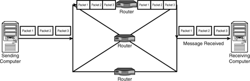
Table 8.1 summarizes the characteristics of the various switching methods.
Table 8.1 Comparison of Switching Methods
WAN Technologies
Having looked at the differences between the various switching methods, we can now take a better look at the technologies used to create WANs. Several technologies can be used to create a WAN—each varies on speed, cost, and implementation difficulty. In this section we explore the various types of WAN technologies and where they are used in today’s networks.
Note
Multiprotocol Label Switching (MPLS) MPLS is a technology designed to speed up network traffic flow by moving away from the use of traditional routing tables. The WAN technologies discussed in this section may use MPLS but because it is associated with network routing, it was included in Chapter 5, “TCP/IP Addressing and Routing.”
X.25
X.25 was one of the original packet-switching technologies, but today it has been replaced in many applications by Frame Relay, which you learn about in the next section. Various telephone companies, along with network providers, developed X.25 in the mid-1970s to transmit digital data over analog signals on copper lines. Because so many entities had their hands in the development and implementation of X.25, it works well on many kinds of networks with different types of traffic. X.25 is one of the oldest standards, and therein lies both its greatest advantage and its greatest disadvantage. On the upside, X.25 is a global standard that can be found all over the world. On the downside, its original maximum transfer speed is 56Kbps, which is reasonable when compared to other technologies in the mid-1970s but slow and cumbersome today. However, in the 1980s a digital version of X.25 was released, increasing throughput to a maximum of 64Kbps. This, too, is slow by today’s standards.
Because X.25 is a packet-switching technology, it uses different routes to get the best possible connection between the sending and receiving device at a given time. As conditions on the network change, such as increased network traffic, so do the routes that the packets take. Consequently, each packet is likely to take a different route to reach its destination during a single communication session. The devices that make it possible to use X.25 service are called packet assemblers/disassemblers (PAD). A PAD is required at each end of the X.25 connection.
Frame Relay
Frame Relay was a step up from X.25 and provided a faster form of packet switching networking than X.25. Frame Relay is a wide area networking protocol that operates at the data-link layers of the OSI model. The OSI model is discussed in detail in Chapter 9, “OSI Model.” Frame Relay enables data transmission for intermittent traffic between LANs and between end points in a WAN.
Frame Relay was designed to provide standards for transmitting data packets in high-speed bursts over digital networks, using a public data network service. Frame Relay is a packet-switching technology that uses variable-length packets. Essentially, Frame Relay is a streamlined version of X.25. It uses smaller packet sizes and fewer error-checking mechanisms than X.25, and it has less overhead than X.25.
Frame relay typically operates over permanent virtual circuits (PVC), meaning that data transmissions follow a known route and no need exists for the transmitting devices to figure out which route is best to use at a destination. Like X.25, Frame Relay uses addressing information in each frame header to determine where packets should go. Frame Relay can be implemented on several WAN technologies, including 56Kbps, T1, T3, and ISDN lines.
Exam Alert
Packet switching Remember for the Network+ exam that Frame Relay is a packet-switching technology that uses PVCs.
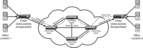
To better understand how Frame Relay works, we will look at some of the components of the technology. The following list outlines some of these components and their function:
• Frame Relay Access Device or Frame Relay Assembler/Disassembler (FRAD)—The FRAD is a device located on the local area network designed to modify data packets by placing header and trailer information on outgoing packets to allow them to travel on the Frame Relay network. The addition of information to the data packets is known as encapsulation. On the receiving end, the header and trailer information is stripped from the data packets (decapsulation). The FRAD may be a dedicated hardware device or part of the function of a specialized router.
• Frame Relay link—The Frame Relay link refers to the media used to connect the local network to the Frame Relay switch. This link may be a T1/T3 link, ISDN or fiber.
• Frame Relay switch—The Frame Relay switch is responsible for routing the frames after they enter the Frame Relay network. A frame may pass through several Frame Relay switches before reaching its destination. A Frame Relay switch can be part of a private network and owned by a particular company and often, the Frame Relay switch is part of a public network that can be leased.
• Backbone media—The backbone is responsible for connecting the Frame Relay switches. This backbone link is often fiber or T1/T3 links. The wiring of the backbone is typically a mesh topology allowing for redundant links interconnecting the Frame Relay switches.
• Virtual circuit—The virtual circuit starts from the local network and the FRAD and connects to the FRAD on the receiving end. The virtual link is often a PVC.
Figure 8.4 shows the components of a Frame Relay network.
Figure 8.4 Components of a Frame Relay network.
Additional terms you will encounter when reading about Frame Relay networks include data terminal equipment (DTE), data circuit terminating equipment (DCE), and data link connection identifier (DLCI).
• Data terminal equipment (DTE)—In the Frame Relay world, the term DTE refers to terminating equipment located with a company’s network. Termination equipment includes such hardware as end user systems, servers, routers, bridges, and switches.
• Data circuit-terminating equipment (DCE)—DCE refers to the equipment owned by the carrier. This equipment provides the switching services for the network and therefore is responsible for actually transmitting the data through the WAN.
• Data link connection identifier (DLCI)—The DLCI is a number that identifies the logical circuit between the router and the Frame Relay switch.
As previously mentioned, Frame Relay uses virtual circuits to create a communication channel. These virtual circuits establish a bidirectional communication link from DTE devices.
T-Carrier Lines
T-carrier lines are high-speed lines that can be leased from telephone companies. T-carrier lines can support both voice and data transmissions and are often used to create point-to-point private networks. Four types of T-carrier lines are available:
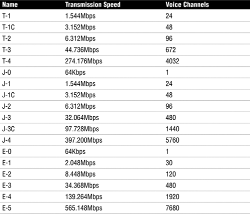
• T-1—T1 lines offer transmission speeds of 1.544Mbps, and they can be used to create point-to-point dedicated digital communication paths. T1 lines have commonly been used for connecting LANs.
• T-2—T2 leased lines offer transmission speeds of 6.312Mbps. T2 lines accomplish this by using 96 64Kbps B channels.
• T-3—T3 lines offer transmission speeds of up to 44.736Mbps, using 672 64Kbps B channels.
• T-4—T4 lines offer impressive transmission speeds of up to 274.176Mbps by using 4,032 64Kbps B channels.
Of these T-carrier lines, the ones commonly associated with networks are T-1 and T-3 lines, which are discussed further in the following sections.
T-1/E-1/J-1 Lines
T1 (also known as a leased line) is a dedicated digital circuit leased from the telephone company. This creates an always-open, always-available line between you and whomever you choose to connect to when you establish the service. T1 lines also eliminate the “one call per wire” limitation by using a method called multiplexing, or muxing. Using a device called a multiplexer, the signal is broken into smaller pieces and assigned identifiers. Multiple transmissions are divided by the multiplexer and transmitted across the wire simultaneously. When the signals reach their destination, they are put back in the proper order and converted back into the proper form.
Having T1 service used to be the way to show someone you were serious about your particular communication needs. T1 lines were expensive; however, their prices have fallen in the past few years, as other technologies have begun to rival their transmission rates. T1 offers data rates up to 1.544Mbps. The obvious advantages of a T1 line are its constant connection—no dial-up or other connection is required because it is always on—and it can be reliably budgeted because it has a fixed monthly cost. In addition, the transfer rate is guaranteed because it, like a telephone call, is a private circuit. Many companies use T1 lines as their pipelines to the Internet.
It is important to point out that T-carrier is the designation to the technology used in the United States and Canada. In Europe, they are referred to as E-carriers and in Japan, J-carriers. Table 8.2 shows the T/E/J carriers.
Table 8.2 Comparing T/E/J Carriers
T3 Lines
For a time, the speeds offered by T1 lines were sufficient for all but a few organizations. As networks and the data they support expanded, T1 lines did not provide enough speed for many organizations. T3 service answered the call by providing transmission speeds of 44.736Mbps.
T3 lines are dedicated circuits that provide very high capacity and are generally used by large companies, ISPs, or long-distance companies. T3 service offers all the strengths of a T1 service (just a whole lot more), but the costs associated with T3 limits its use to the few organizations that have the money to pay for it.
Note
Fractional T Because of the cost of a T-carrier solution, it is possible to lease portions of a T-carrier service. Known as fractional T, you can subscribe and pay for service based on 64Kbps channels.
SONET/OCx Levels
In 1984 the U.S. Department of Justice and AT&T reached an agreement stating that AT&T was a monopoly that needed to be divided into smaller, directly competitive companies. This created a challenge for local telephone companies, which were then faced with the task of connecting to an ever-growing number of independent long-distance carriers, each of which had a different interfacing mechanism. Bell Communications Research answered the challenge by developing SONET, a fiber-optic WAN technology that delivers voice, data, and video at speeds starting at 51.84Mbps. Bell’s main goals in creating SONET were to create a standardized access method for all carriers within the newly competitive U.S. market and to unify different standards around the world. SONET is capable of transmission speeds between 51.84Mbps to 40Gbps and beyond.
Exam Alert
SONET For the Network+ exam, remember that SONET is an optical interface standard that allows transmission equipment from multiple vendors to talk together over fiber-optic lines.
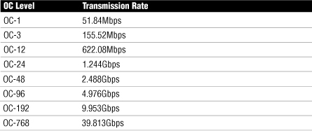
One of Bell’s biggest accomplishments with SONET was that it created a new system that defined data rates in terms of Optical Carrier (OCx) levels. Table 8.3 contains the OCx levels you should be familiar with.
Table 8.3 OCx Levels and Transmission Rates
Exam Alert
OCx levels OC, or optical carrier levels, represent the range of digital signals that can be carried on the SONET fiber-optic network. Each OC level defines the speed at which it operates.
Asynchronous Transfer Mode (ATM)
When it was introduced in the early 1990s, ATM was heralded as a breakthrough technology for networking because it was an end-to-end solution, ranging in use from a desktop to a remote system. Though promoted as both a LAN and WAN solution, ATM did not live up to its hype because of associated implementation costs and a lack of standards. The introduction of Gigabit Ethernet, which offered great transmissions speeds and compatibility with existing network infrastructure, further dampened the momentum of the ATM bandwagon.
ATM is a packet-switching technology that provides transfer speeds commonly ranging from 1.544Mbps to 622Mbps. It is well suited for a variety of data types, such as voice, data, and video. Using fixed-length packets, or cells, that are 53 bytes long, ATM can operate much more efficiently than variable-length-packet packet-switching technologies such as Frame Relay. Having a fixed-length packet allows ATM to be concerned only with the header information of each packet. It does not need to read every bit of a packet to determine the beginning and end of the packet. ATM’s fixed cell length also makes it easily adaptable to other technologies as they develop. Each cell has 48 bytes available for data, with 5 bytes reserved for the ATM header.
ATM uses virtual connections to connect end points in an ATM network. The ATM network can use PVCs or SVCs. PVC and SVC were discussed earlier in this chapter. ATM networks using PVCs have the following characteristics:
• PVC is permanent.
• PVC cells cannot take alternate routes to an end point in the event of circuit failure.
• Even when not in use, bandwidth is still reserved for the PVC.
ATM using SVC has the following characteristics:
• SVCs are dynamically connected on an as-needed basis.
• After an SVC connection is released, resources are available for other applications.
• ATM cells can take an alternate route to an end point in the event of failure.
ATM is compatible with the most widely used and implemented networking media types available today, including single-mode and multimode fiber, coaxial cable, unshielded twisted pair, and shielded twisted pair. Although it can be used over various media, the limitations of some of the media types make them impractical choices. ATM can also operate over other media, including FDDI, T-1, T-3, SONET, OC-3, and Fiber Channel.
Integrated Services Digital Network (ISDN)
ISDN is a dial-up technology capable of transmitting voice and data simultaneously over the same physical connection. Using ISDN, users are able to access digital communication channels via both packet- and circuit-switching connections. ISDN is much faster than a dial-up modem connection. To access ISDN, a dedicated phone line is required, and this line is usually paid for through a monthly subscription. You can expect these monthly costs to be significantly higher than those for a dial-up modem account.
Exam Alert
ISDN switching ISDN is a circuit-switched telephone network system designed to allow digital transmission of voice and data over ordinary telephone copper wires.
To establish an ISDN connection, you dial the number for the end of the connection, much as you would with a conventional phone call or modem dial-up connection. A conversation between the sending and receiving devices is then established. The connection is dropped when one end disconnects or hangs up. The line pickup of ISDN is very fast, allowing a connection to be established, or brought up, very quickly—much more quickly than a conventional phone line.
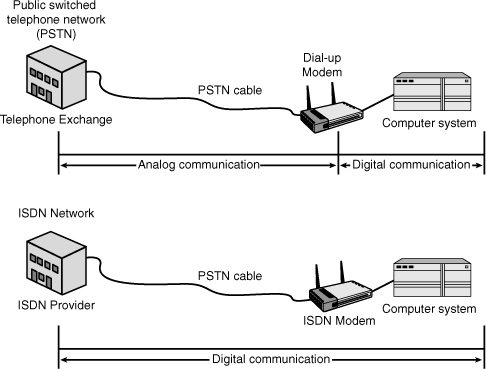
Although ISDN uses the same media as PSTN or regular phone wires, it does so in a much different manner. PSTN was not originally designed for data transfer, so a dial-up modem is used to convert PSTN analog signals to digital signals that carry data and network traffic. One of the problems with this has been that not all of the communication is digital. The telephone exchange to the modem is an analog signal, and from the modem to the computer is a digital signal.
ISDN, however, uses digital communication right from the ISDN exchange to the network end point. Because the entire communication path is digital, data transfer is faster and the analog to digital conversion is not necessary. Figure 8.5 shows a simple comparison between PSTN links and ISDN links.
Figure 8.5 Comparing PSTN and ISDN communication.
ISDN has two defined interface standards—Basic Rate Interface (BRI) and Primary Rate Interface (PRI)—which are discussed in the following sections.
Basic Rate Interface (BRI)
BRI defines a communication line that utilizes three separate channels. There are two B (that is, bearer) channels of 64Kbps each and one D (that is, delta) channel of 16Kbps. The two B channels are used to carry digital information, which can be either voice or data. The B channels can be used independently to provide 64Kbps access or combined to utilize the entire 128Kbps. The D channel is used for out-of-band signaling.
Tip
2B+D BRI ISDN is sometimes referred to as 2B+D. This abbreviation simply refers to the available channels.
To use BRI ISDN, the connection point must be within 5,486 meters (18,000 feet) of the ISDN provider’s BRI service center. In addition, to use BRI ISDN, special equipment is needed, such as ISDN routers and ISDN terminal adapters.
Primary Rate Interface (PRI)
PRI is a form of ISDN that is generally carried over a T1 line and can handle transmission rates of up to 1.536Mbps. PRI is composed of 23 B channels (30 in Europe), each providing 64Kbps for data/voice, and one 64Kbps D channel.
Note
Leased lines ISDN is considered a leased line because access to ISDN is leased from a service provider.
Review Break
Comparing BRI and PRI ISDN
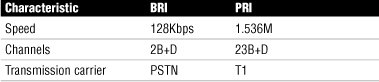
Table 8.4 compares BRI and PRI ISDN.
Table 8.4 BRI and PRI ISDN Comparison
Exam Alert
PRI+BRI For the Network+ exam, be sure you can identify the characteristics of ISDN, including the speeds of BRI and PRI.
Review Break
WAN Technology Summary
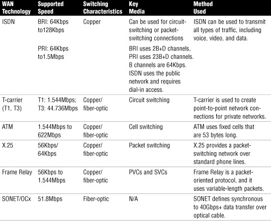
Table 8.5 summarizes the main characteristics of some of the various WAN technologies discussed in this chapter. You can use this table as an aid in reviewing before you take the Network+ exam.
Table 8.5 WAN Technology Overview
Internet Access Technologies
For most organizations, the Internet is an essential component of their business. Many of the business applications such as email, videoconferencing, and VPN connections operate without the Internet. For businesses, the debate is not whether to have an Internet connection, but choosing the type of Internet connection that best suits an organization’s needs.
In this section we compare the various Internet access technologies. The one chosen by an organization depends on many factors, including transfer speeds, availability, and cost. We start by looking at the oldest and slowest method of Internet access, the plain old telephone system (POTS).
POTS Internet Access
Though slow by today’s standards, many people still connect to the Internet using a telephone line and modem. Mainly, POTS Internet access is used in rural areas where higher speed Internet access technologies are not available. Businesses and individuals located in remote areas may have no choice but to use POTS. Others may use POTS if their Internet usage is low and used only for such applications as email.
Internet access through a phone system requires two things: a modem and a dial-up access account through an ISP. As you might recall from Chapter 3, “Networking Components and Devices,” modems are devices that convert the digital signals generated by a computer system into analog signals that can travel across a phone line. A computer can have either an internal or external modem. External modems tend to be less problematic to install and troubleshoot because they don’t require reconfiguration of the host system. Internal modems use one of the serial port assignments (that is, a COM port) and must therefore be configured not to conflict with other devices.
The second piece of the puzzle, the dial-up ISP account, can easily be obtained by contacting one of the many local, regional, or national ISPs. Most ISPs offer a range of plans normally priced based on the amount of time the user is allowed to spend online. Almost without exception, ISPs offer 56Kbps access, the maximum possible under current standards. Most ISPs also provide email accounts, access to newsgroup servers, and often small amounts of web space.
It is a good idea to research an ISP choice carefully. Free services exist, but they generally restrict users to a certain number of online hours per month or use extensive banner advertising to pay for the services. Normally, you pay a monthly service fee for an ISP; doing so provides a degree of reassurance because the ISP can be held accountable. Paid-for service also tends to provide a higher level of support.
Another big consideration for dial-up Internet access is how many lines the ISP has. ISPs never have the same number of lines as subscribers; instead, they work on a first-come, first-served basis for dial-up clients. This means that on occasion, users get busy signals when they try to connect. Before signing up for a dial-up Internet access account, ask the company what its ratio of lines to subscribers is and use that figure as part of your comparison criteria.
With a modem and an ISP account, you are ready to get connected. But what happens if things do not run as planned? Welcome to the interesting and sometimes challenging world of troubleshooting dial-up connections.
POTS Troubleshooting Procedures
Troubleshooting a dial-up connection problem can be tricky and time consuming because you must consider many variables. In fact, of the remote connectivity mechanisms discussed in this chapter, you are far more likely to have problems with a POTS connection than any of the others. The following are some places to start your troubleshooting under various conditions.
Note
Technical support In some cases, users may not use an ISP at all and instead dial another system on the corporate network directly. In that case, all the troubleshooting steps in this section apply, except that you have to rely on the technical support capabilities of the person responsible for the remote system rather than the ISP if you have a problem.
If the user is unable to dial out, try the following:
• Check physical connections—The most common problem with modem connections is that something has become unplugged; modems rarely fail after they initially work. For an external modem, you also need to verify that the modem has power.
• Check that there is a dial tone on analog lines—You can do this by plugging a normal phone into the socket and seeing whether you can dial out. Also, a modem generally has a speaker, and you can set up the modem to use the speaker so that you can hear what is going on.
If the user can dial out but cannot connect to the network, try the following:
• Make sure that the user is dialing the correct number—This suggestion sounds obvious, but sometimes numbers change or are entered incorrectly.
• Call the ISP—You can call the ISP to determine whether it is having problems.
• Check the modem speaker—Find out whether you are getting busy signals from the ISP by turning on the modem speaker.
If the user can dial out and can get a connection but is then disconnected, try the following:
• Make sure that the modem connection is configured correctly—The most common modem configuration is 8 data bits, 1 stop bit, and no parity (commonly referred to as eight-one-none).
• Check the username and password—Make sure that the correct username and password combination is configured for the dial-up connection.
• Verify that the connection settings are correct—Pay particular attention to things such as the IP address. Nearly all ISPs assign IP addresses through DHCP, and trying to connect with a statically configured IP address is not permitted.
• Make sure that the user has not exceeded a preset connection time limit—Some ISPs restrict the number of monthly access hours. If the user has such a plan, check to make sure that some time credit is left.
• Try specifying a lower speed for the connection—Modems are designed to negotiate a connection speed with which both devices are comfortable. Sometimes, during the negotiation process, the line can be dropped. Initially setting a lower speed might get a connection. You can then increase the modem speed to accommodate a better connection.
Troubleshooting Poor Connection Speeds
Even if you are not having a problem connecting, you might find that the speed of modem connections is problematic. Such problems are not uncommon. The modem might say it can handle a certain speed, and the ISP might advertise the same, but often you simply cannot get the maximum supported speed on a dial-up connection. There are many possible reasons; some of them you can do something about, and some of them you can’t. Here are some of the reasons speeds might not be as fast as expected:
• Poor line quality—In some areas, the quality of the telephone lines and exchange equipment can reduce the maximum possible connection speed.
• Incorrectly configured modem—The modem configuration is important in ensuring the highest possible connection speed. In particular, for external modems, you should check the configuration of the serial port the modem is connected to. Defaults sometimes restrict the speed of the port. Generally, though, an incorrectly configured modem or serial port will prevent the modem from making a connection at all, not just impact the speed.
• Poor-quality modems—Perhaps less of an issue now than in the past, poor-quality modems can contribute to poor connection speeds and connectivity problems. Paying the extra money for a good-quality modem is worth the savings in frustration alone.
After all this, it is worth mentioning that after you establish a connection, whatever the speed, you are still at the mercy of the ISP. Even a 56Kbps link might be too slow if the ISP’s networking equipment or Internet connection can’t keep up with demand. Unfortunately, there is no way to know whether the bottleneck is with the ISP or the modem.
Modem-Specific Troubleshooting
Typically, modems are reliable devices. They have no moving parts, and chances are that after you have installed, configured, and tested a modem, you won’t have to play around with it again. However, exceptions can occur, and you should be aware of the following modem-specific troubleshooting measures:
• Make sure that you have the latest drivers—For any type of modem, make sure that the latest drivers are installed. The drivers supplied with modems typically are not up-to-date, and a visit to the modem manufacturer’s website (from another computer) might yield more up-to-date drivers. Try to avoid using generic drivers or those provided with operating systems where possible. Even if they work, which they often don’t, they probably won’t offer all the features of the proper drivers.
• Check for resource conflicts—On older PCs, make sure that no conflicts exist between internal modems and other system resources. For external devices, make sure that serial ports are enabled and configured correctly.
• Check for firmware updates—Both internal and external modems have updatable firmware chips. Check the modem manufacturer’s website to ensure that you have the latest version of the firmware. (Note that firmware updates should be completed only if they fix a specific problem you are having.)
If you are confident that a modem is installed and configured correctly, but it’s still not working properly, you can test and configure it by using special commands called the AT command set. These commands are mentioned briefly in Chapter 3 but they are worthy of a more detailed discussion here; they are often useful for troubleshooting modems and related connectivity problems.
You can use AT commands through a communications application to talk directly to the modem. On Windows platforms, you can use the HyperTerminal utility. On most common Linux distributions, you can use the minicom utility. After you have established a session with the modem, you can issue AT commands directly to the modem, which will respond in different ways, depending on the command. Table 8.6 lists some of the most commonly used AT commands.
Table 8.6 Commonly Used AT Commands
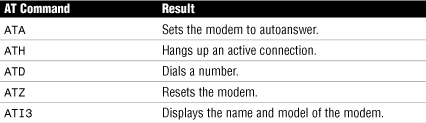
In general, getting the modem to respond to an ATZ command is a good enough indicator that the modem is functioning.
Exam Alert
AT commands Be prepared to identify the function of basic AT commands for the Network+ exam.
POTS Challenge Solution: In this challenge, as a technician you can check all the modem configurations, and they appear to be correct. Find out whether call waiting is enabled on the line; if it is, modify the modem dial string to disable call waiting before dialing an Internet connection.
xDSL
DSL is an Internet access method that uses a standard phone line to provide high-speed Internet access. DSL is available only in certain areas, although as the telephone companies try to cash in on the broadband Internet access market, the areas of coverage are likely to increase.
DSL offers phone and data transmissions over a standard phone connection. DSL is most commonly associated with high-speed Internet access; because it is less expensive than technologies such as ISDN, it is often used in homes and small businesses. With DSL, a different frequency can be used for digital and analog signals, which means that you can talk to a friend on the phone while you’re uploading data.
DSL arrived on the scene in the late 1990s, and it brought with it a staggering number of flavors. Together, all these variations are known as xDSL:
• Asymmetric DSL (ADSL)—Probably the most common of the DSL varieties is ADSL. The word asymmetric describes different bands on the line: One band is used for POTS and is responsible for analog traffic, the second band is used to provide upload access, and the third band is used for downloads. With ADSL, downloads are faster than uploads.
• Symmetric DSL (SDSL)—SDSL offers the same speeds for uploads and for downloads, making it most suitable for business applications such as web hosting, intranets, and ecommerce. It is not widely implemented in the home/small business environment and cannot share a phone line.
• ISDN DSL (IDSL)—ISDN DSL is a symmetric type of DSL commonly used in environments where SDSL and ADSL are unavailable. IDSL does not support analog phones.
• Rate Adaptive DSL (RADSL)—RADSL is a variation on ADSL that can modify its transmission speeds based on the signal quality. RADSL supports line sharing. RADSL is a asymmetric form of DSL.
• Very High Bit Rate DSL (VHDSL)—VHDSL is an asymmetric version of DSL and, as such, can share a telephone line. VHDSL supports high bandwidth applications such as VoIP and HDTV. VHDSL can achieve data rates up to 10Mbps and up, making it the fastest available form of DSL.
• High Bit Rate DSL (HDSL)—HDSL is a symmetric technology that offers identical transmission rates in both directions. HDSL does not allow line sharing with analog phones.
Why are there are so many DSL variations? The answer is that each flavor of DSL is aimed at a different user, business, or application. Businesses with high bandwidth needs are more likely to choose a symmetric form of DSL, whereas budget-conscious environments such as home offices are likely to choose an option that allows phone line sharing at the expense of bandwidth. When you’re working in a home/small office environment, you should expect to work with an ADSL system.
Exam Alert
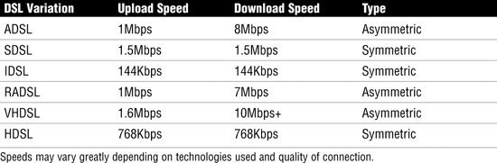
Symmetric or asymmetric For the Network+ exam you should know which DSL options are asymmetric DSL (ADSL) or symmetric (SDSL, HDSL). ADSL is used for Internet access, where fast downstream is required, but slow upstream is not a problem. Symmetric offers high speed transfers in both directions.
DSL options can be either a shared or a dedicated link. ADSL, for instance, is a shared DSL connection. The shared connection means that a single telephone line can support both voice and Internet service. This is possible because a telephone cable uses two frequencies: high and low. The low frequency is used for DSL Internet, whereas the high frequency is used for voice.
If you see the term rate adaptive used with a DSL technology, it means that the speed of the connection fluctuates. This fluctuation is caused by several factors, including the distance between the DSL provider and the Internet system, the condition of the physical line used by the DSL connection, or the interference on the line. This makes technologies such as ADSL inconsistent in terms of speed, but for most day-to-day applications, these speed fluctuations will go largely unnoticed.
If there are shared DSL links, there must be dedicated DSL links. A dedicated DSL link is a more costly Internet solution but provides some clear advantages. Business DSL solutions such as SDSL provide a dedicated DSL link over copper from the service provider to the Internet system. A dedicated DSL line is not used for regular voice transmissions.
Table 8.7 summarizes the expected speeds of the various DSL options.
Note
Broadband The term broadband refers to high-speed Internet access. Both DSL and cable modem are common broadband Internet technologies. Broadband routers and broadband modems are network devices that support both DSL and cable.
Troubleshooting DSL is similar to troubleshooting any other Internet connection. The following are a few things to check when users are experiencing problems with a DSL connection:
• Physical connections—The first place to look when troubleshooting a DSL problem is the network cable connections. From time to time, these cables can come loose or inadvertently be detached, and they are often overlooked as the cause of a problem. DSL modems typically have a minimum of three connections: one for the DSL line, one for the local network, and one for the power. Make sure that they are all plugged in appropriately.
• NIC—While you’re checking the cable at the back of the system, take a quick look to see whether the network card LED is lit. If it is not, something could be wrong with the card. It might be necessary to swap out the network card and replace it with one that is known to be working.
• Drivers—Confirm that the network card is installed and has the correct drivers. Many times, simply using the most up-to-date driver can resolve connectivity issues.
• Protocol configuration—The device you are troubleshooting might not have a valid IP address. Confirm the IP address by using the appropriate tool for the operating system being used—for example, winipcfg, ipconfig, or ifconfig. If the system requires the automatic assignment of an IP address, confirm that the system is set to obtain an IP address automatically. It might be necessary to use the ipconfig /release and ipconfig /renew commands to get a new IP address.
• DSL LEDs—Each DSL box has an LED on it. The light sequences are often used to identify connectivity problems or problems with the box itself. Refer to the manufacturer’s website for specific information about error codes and LEDs, but remember the basics: a link light should be on to indicate that the physical connection is complete, and a flashing LED indicates that there is activity on the connection.
Exam Alert
Remember the visual indicators When troubleshooting remote connectivity on a cable or DSL modem, use the LEDs that are always present on these devices to aid in your troubleshooting process.
Ultimately, if none of these steps cure or indicate the cause of the problem, you might have to call the DSL provider for assistance.
DSL Challenge Solution: Verify that the phone cable between the modem and the wall jack are connected correctly. If the connection appears complete, consider trying another cable between the DSL modem and the wall jack. If that fails, or you do not have another cable available, contact the DSL service provider’s technical support line.
Cable Internet Access
Cable Internet access is an always-on Internet access method available in areas that have digital cable television. Not all cable TV providers offer Internet access, but an increasing number are taking advantage of the relatively simple jump from being cable providers to being ISPs.
Cable Internet access is attractive to many small businesses and home office users because it is both inexpensive and reliable. In the past, most cable providers did not restrict how much use is made of the access. However, with large data transfers associated with today’s Internet usage, many companies are now restricting the amount of upstream or downstream traffic. Additional bandwidth can often be purchased if necessary.
With cable Internet, connectivity is achieved by using a device called a cable modem; it has a coaxial connection for connecting to the provider’s outlet and an unshielded twisted-pair (UTP) connection for attaching directly to a system, hub, or switch.
Cable providers often supply a cable modem for a monthly fee, or it is possible to buy one from the cable company to avoid the monthly charge. Many cable providers offer free or low-cost installation of cable Internet service, which includes installing a network card in a PC. Some providers do not charge for the network card. Cable Internet costs are comparable to a DSL subscription at about $30 to $50 a month. Business-use cable packages offering many additional features and increased bandwidth are also available.
Most cable modems supply a 10Mbps ethernet connection for the home LAN, although you wouldn’t expect the actual Internet connection to reach these speeds. Business often require more speed and features than a regular home user or small office does. Most cable companies offer different packages to accommodate the various Internet needs. To give you a better idea of the options available, Table 8.8 shows the options available from one cable company.
Table 8.8 Cable Internet Sample Packages
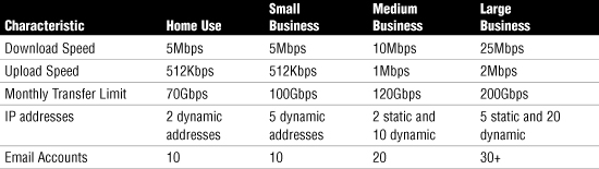
Keep in mind that the information provided in Table 8.8 is an example from a single cable company. Others may offer different packages with various speeds and other features.
Note
MDI-X ports A cable modem is generally equipped with a medium-dependent interface crossed (MDI-X) port, so a straight-through UTP cable can be used to connect the modem to a system.
One disadvantage of cable access is that you share the available bandwidth with everyone else in your cable area. As a result, during peak times, performance of a cable link might be poorer than in low-use periods. In residential areas, busy times are evenings and weekends, and particularly right after school. In general, though, performance with cable systems is good, and in low-usage periods it can be very fast.
In general, cable Internet access is a low-maintenance system with few problems. When problems do occur, you can try various troubleshooting measures:
• Check the user’s end—Before looking at the cable modem, make sure that the system is configured correctly and that all cables are plugged in. If a hub or switch is used to share the cable Internet access among a group of computers, make sure that the hub or switch is on and functioning correctly.
• Check the physical connections—Like DSL modems, cable modems have three connections: one for the cable signal, one for the local network, and one for the power. Make sure that they are all plugged in appropriately.
• Ensure that the protocol configuration on the system is valid—If an IP address is assigned via DHCP, the absence of an address is a sure indicator that connectivity is at fault. Try obtaining a new IP address by using the appropriate command for the operating system platform you are using. If the IP addresses are statically configured, make sure that they are set correctly. Trying to use any address other than that specified by the ISP might prevent a user from connecting to the network.
• Check the indicator lights on the modem—Most cable modems have indicator lights that show the status of the modem. Under normal conditions, a single light labeled Ready or Online should be lit. Most cable providers provide a manual with the modem that details the functions of the lights and what they indicate in certain states. Generally, any red light is bad. Flashing LEDs normally indicate traffic on the connection.
• Power down the modem—Cycling the power on the modem is a sure-fire way of resetting it. However, it has to be done in a particular order. For instance, turn off the computer, then the cable modem, then unplug all devices. Plug devices in after a few seconds, power on the cable modem first, and then the computer. Refer to the manufacturer for the recommended reboot and power-down process.
• Call the technical support line—If you are sure that the connectors are all in place and the configuration of the system is correct, the next step is to call the technical support line of the cable provider. If the provider is experiencing problems that affect many users, you might get a message while you’re on hold, informing you of the fact. If not, you will eventually get to speak to someone who can help you troubleshoot the problem. One of the good things about cable access is that the cable company can remotely monitor and reset the modem. It should be able to tell you whether the modem is functioning correctly.
Unless the modem is faulty, which is not that common, by this point the user should be back on the Internet—or at least you should fully understand why the user cannot connect. If the problem is with the cable provider’s networking equipment, you and the user simply have to wait for the system to come back on.
Cable Challenge Solution: Verify that the protocol configuration is correct and that all cables are connected correctly. During your investigation, you notice that the Online light of the cable modem is red. After you cycle the power to the modem, the light remains red; you are still unable to obtain a valid IP address. The next step is to contact the cable service provider’s technical support line.
Note
The choice is yours Although the debate about cable versus DSL goes on, it really won’t make that much difference which one we choose. Although cable modem technology delivers shared bandwidth within the local neighborhood, its speeds are marginally higher but influenced by this shared bandwidth. DSL delivers dedicated local bandwidth but is sensitive to distance, which impacts overall performance. With the monthly costs about the same, it really is too close to call.
Satellite Internet Access
Many of us take DSL and cable Internet access for granted, but these technologies are not offered everywhere. For areas where cheaper broadband options are not available, a limited number of Internet options exist. One of the primary ones is Internet via satellite.
Satellite access provides a viable Internet access solution for those who cannot get other methods of broadband. Satellite Internet offers an always-on connection with theoretical speeds advertised anywhere from 512Kbps upload speeds to 2048Kbps download speeds, considerably faster than a 56K dial-up connection. One primary drawback to satellite Internet is the cost, and even with the high price tag, it is not as fast as DSL or cable modem.
Although satellite Internet is slower and more costly than DSL or cable, it offers some attractive features, first of which has to be its portability. Quite literally, wherever you go, you have Internet access with no phone lines or other cables. For businesses with remote users and clients, the benefit to this is clear. But the technology has a far-reaching impact; it is not uncommon to see RVs with a satellite dish on the roof. They have 24/7 unlimited access to the Internet as they travel.
Many companies offer satellite Internet services, as a quick Internet search reveals. These Internet providers offer different Internet packages that vary greatly in terms of price, access speeds, and service. Some target businesses, whereas others aim for the private market.
Two types of broadband Internet satellite services are deployed: one-way and two-way systems. A one-way satellite system requires a satellite card and a satellite dish installed at the end user’s site; this system works by sending outgoing requests on one link using a phone line, with inbound traffic returning on the satellite link. A two-way satellite system, on the other hand, provides data paths for both upstream and downstream data. Like a one-way system, a two-way system also uses a satellite card and a satellite dish installed at the end user’s site; bidirectional communication occurs directly between the end user’s node and the satellite.
Home satellite systems are asymmetric; that is, download speeds are faster than upload speeds. In fact, a home satellite system is likely to use a modem for the uplink traffic, with downloads coming over the satellite link. The exact speeds you can expect with satellite Internet depend on many factors. As with other wireless technologies, atmospheric conditions can significantly affect the performance of satellite Internet access. One additional consideration for satellite Internet is increased latency, which is the time it takes for the signal to travel back and forth from the satellite. In networking terms, this time is high and an important consideration for business applications.
Your ability to troubleshoot satellite Internet connections might be limited. Home satellite Internet is a line-of-sight wireless technology, and the installation configuration must be precise. Because of this requirement, many satellite companies insist that the satellite be set up and configured by trained staff members. In fact, if you install a satellite system in a way that does not accord with the manufacturer’s recommendations, you might void any warranties.
Given this limitation, troubleshooting satellite connections often requires you to concentrate less on connectivity issues and more on physical troubleshooting techniques. Perhaps more than for any other Internet technology, calls to technical support occur very early in the troubleshooting process. Be aware of the following issues that are a part of satellite Internet:
• Rain fade—Rain fade refers to signal loss due to moisture interference. The general rule is that the smaller the dish, the more susceptible it is to rain fade. Home and small businesses use small dishes.
• Latency—Latency refers to the time lapse between sending or requesting information and the time it actually takes to return. As you might expect, satellite communication experiences high latency because of the distance it has to travel.
• Line of sight—Despite the distance, satellite is basically a line of sight technology. This means that the path between the satellite dish and the satellite needs to be as unobstructed as possible.
Wireless Wide Area Networking
As discussed in Chapter 7, “Wireless Networking,” a wireless LAN (WLAN) allows network users to connect to the local network and move around that network without wires. WLANs are typically restricted to a single location. To use the Internet and remotely access local area networks away from the LAN, wireless wide area networking is used.
A wireless wide area network (WWAN), covers a much larger area than WLANs do. Wireless coverage is generally offered on a city and even nationwide level, with wireless network infrastructure provided by a wireless service carrier. WWANs allow remote access to the Internet, email, and resources of a LAN. Wireless WANs use cellular networks for data transmission, a WAN modem connects to a base station on the wireless networks via radio waves. The radio tower then carries the signal to a mobile switching center, where the data is passed on to the appropriate network.
A few years ago, it would have been inconceivable to walk into your local coffee shop with your laptop under your arm and surf the web while drinking a latte. But today, it is common to see people surfing the web in many public places. This is made possible by subscribing to a wireless Internet service provider (WISP) or connecting to a company’s local wireless router.
A WISP provides public wireless Internet access known as hotspots. Hotspots provide Internet access for mobile network devices such as laptops, handheld computers, and cell phones in airports, coffee shops, conference rooms, and so on. A hotspot is created using one or many wireless access points near the hotspot location.
Client systems might need to install special application software for billing and security purposes; others require no configuration other than obtaining the network name (SSID). Hotspots are not always a pay-for service because companies use them as a marketing tool to lure Internet users to their businesses.
As of today, hotspots are not everywhere, but finding them is not difficult. Typically, airports, hotels, and coffee shops advertise that they offer Internet access for customers or clients. In addition, WISP providers list their hotspot sites online so that they are easily found.
Establishing a connection to a wireless hotspot is a straightforward process. If not equipped with built-in wireless capability, laptops will require an external wireless adapter card. With the physical requirements of the wireless card taken care of, the steps to connect are as follows:
1. When you arrive at the hotspot site, power up your laptop. In some instances, you might need to reboot your system if it was on standby to clear out old configuration settings.
2. The card might detect the network automatically. If this is the case, configuration settings, such as the SSID, will be automatically detected, and the wireless Internet will be available. If Internet access is free, there is little else to do; if it is a paid-for service, you will need to enter a method of payment. One thing to remember is to verify that you are using encryption for secure data transfer.
3. If for some reason the wireless settings are not automatically detected, you will need to open up your wireless NIC’s configuration utility and manually set the configurations. These settings can include setting the mode to infrastructure, inputting the correct SSID, and setting the level of encryption used.
In addition to using a WISP, some companies such as hotels, cafes, and so on provide wireless Internet access by connecting a wireless router to a DSL or cable Internet connection. The router becomes the wireless access point to which the users connect, and it allows clients to connect to the Internet through the broadband connection. The technology is based on the 802.11 standards, typically 802.11b/g, and client systems require only an internal or external wireless adapter.
Note
Troubleshooting wireless connectivity There will be times when the Internet connection fails to work. Troubleshooting a wireless connectivity issue is covered in Chapter 11, “Troubleshooting Procedures and Best Practices.”
Summary
This chapter outlines the technologies used to create WANs and various Internet access technologies. Each WAN technology has advantages and disadvantages, making some of them well suited for certain environments and completely impractical in others. Each of the technologies varies in terms of media, speed, availability, and cost.
Public networks such as the PSTN and the Internet are the most widely used methods of establishing WANs, due in part to their availability, accessibility, and perhaps most importantly, their cost. The downsides of using these networks are security and speed issues.
Private networks allow secure communications between devices; however, the costs of dedicated private networks make them unattainable for many small companies. In addition, the implementation and management of private networks can often be more complex than that of public networks.
Several switching methods are used to establish communication between devices. With packet switching, messages are broken into smaller pieces, with each packet assigned source, destination, and intermediate node addresses. These packets are independently routed toward the destination address. Circuit switching, on the other hand, requires a dedicated physical connection between the sending and receiving devices. Data transmissions follow the dedicated path to the receiving device. Message switching sends the entire message via intermediate devices, such as computers, temporarily storing and then forwarding the messages.
ATM and SONET are examples of packet-switching networks that use virtual circuits, either PVC or SVC, to make a connection between the sender and receiver. ISDN uses the PSTN wires and is most often associated with circuit switching. ISDN provides point-to-point digital communication and requires an ISDN modem on each end of the communication link.
There are several methods of accessing the Internet all varying in terms of speeds, range, cost, and complexity. Cable and DSL Internet are popular Internet access solutions for home users and small business. Many types of DSL versions exist, including VHDLS used for high-speed data transfers. The DSL versions are either symmetric, in which both uploads and downloads are the same speed, or asymmetric, in which uploads are slower than downloads.
They are a cost-effective solution offering broadband speeds and always-on service. Satellite and wireless Internet access take availability outside the home to practically anywhere. Dial-up Internet access, although slow, remains readily available and a viable solution for many situations.
Key Terms
• ATM
• PSTN
• PVC
• SVC
• Modem
• ISDN
• BRI
• PRI
• T1/E1
• T3/E3
• DSL
• POTS
• WWAN
• WISP
• X.25
• SONET/OC-x
Apply Your Knowledge
Exercise
7.1 Investigating WAN Options
Estimated time: 30 minutes
Because you are unlikely to have the equipment or facilities to create your own WAN, this exercise requires that you investigate the WAN options that would be available to you if you were to create a WAN from your location to another.
Your research should include visiting the website of a local telecommunications provider and ascertaining the options open to you. Given that financial considerations are generally a major factor in a decision such as this, you should look at the lower-cost options such as cable, DSL, or ISDN in preference to leased-line circuits, such as T1 lines. From your research you should be able to answer the following questions:
• Which services are available in your location?
• Which services offer the best value for the money, based on available bandwidth, cost of installation, ongoing costs (line/equipment rental), maintenance, and call charges, if applicable?
• Which of the available services would you choose, and what would the estimated annual cost be for that service?
Although you should not sign up for any of the services during the course of this exercise, through this exercise you will gain valuable information because this is exactly the kind of project you are likely to be assigned when working in a real-world situation as an administrator. Evaluation and recommendation of products is an important element of a network administrator’s role.
Exam Questions
1. Your company currently uses a standard PSTN communication link to transfer files between LANs. Until now, the transfer speeds have been sufficient for the amount of data that needs to be transferred. Recently, a new application was purchased that requires a minimum transmission speed of 1.5Mbps. You have been given the task of finding the most cost-effective solution to accommodate the new application. Which of the following technologies would you use?
![]() A. T3
A. T3
![]() B. X.25
B. X.25
![]() C. T1
C. T1
![]() D. BRI ISDN
D. BRI ISDN
2. You are troubleshooting an ATM network that uses PVC connections. Which of the following is not a characteristic of a PVC?
![]() A. PVC is permanent.
A. PVC is permanent.
![]() B. PVC cells cannot take alternate routes to an end point in the event of circuit failure.
B. PVC cells cannot take alternate routes to an end point in the event of circuit failure.
![]() C. Even when not in use, bandwidth is still reserved for the PVC.
C. Even when not in use, bandwidth is still reserved for the PVC.
![]() D. SVCs are dynamically connected on an as-needed basis.
D. SVCs are dynamically connected on an as-needed basis.
3. Which of the following statements are true of ISDN? (Choose the two best answers.)
![]() A. BRI ISDN uses 2B+1D channels.
A. BRI ISDN uses 2B+1D channels.
![]() B. BRI ISDN uses 23B+1D channels.
B. BRI ISDN uses 23B+1D channels.
![]() C. PRI ISDN uses 2B+1 D channels.
C. PRI ISDN uses 2B+1 D channels.
![]() D. PRI ISDN uses 23B+1D channels.
D. PRI ISDN uses 23B+1D channels.
4. You have been hired to establish a WAN connection between two offices—one in Vancouver and one in Seattle. The transmission speed can be no less than 2Mbps. Which of the following technologies could you choose?
![]() A. T1
A. T1
![]() B. PSTN
B. PSTN
![]() C. T3
C. T3
![]() D. ISDN
D. ISDN
5. You have been asked to recommend a DSL Internet solution for a large company. The company is not concerned about download speeds but wants a fast version of DSL for videoconferencing. Which of the following DSL options would you choose?
![]() A. VHDSL
A. VHDSL
![]() B. SDSL
B. SDSL
![]() C. IDSL
C. IDSL
![]() D. HDSL
D. HDSL
6. You are designing a Frame Relay network. Which of the following components are associated with Frame Relay networks? (Choose all that apply.)
![]() A. FRAD
A. FRAD
![]() B. Frame Relay switch
B. Frame Relay switch
![]() C. Frame Relay bridge
C. Frame Relay bridge
![]() D. Virtual circuit
D. Virtual circuit
![]() E. Rate adaptive switch
E. Rate adaptive switch
7. Because of recent cutbacks, your boss approaches you, demanding an alternative to the company’s costly dedicated T1 line. Only small amounts of data will require transfer over the line. Which of the following are you likely to recommend?
![]() A. ISDN
A. ISDN
![]() B. FDDI
B. FDDI
![]() C. The PSTN
C. The PSTN
![]() D. X.25
D. X.25
8. Which of the following technologies requires a logical connection between the sending and receiving devices?
![]() A. Circuit switching
A. Circuit switching
![]() B. Virtual-circuit packet switching
B. Virtual-circuit packet switching
![]() C. Message switching
C. Message switching
![]() D. High-density circuit switching
D. High-density circuit switching
9. Which of the following statements is true of satellite Internet access?
![]() A. Satellite Internet access is available only in urban areas.
A. Satellite Internet access is available only in urban areas.
![]() B. Satellite Internet communication is symmetric.
B. Satellite Internet communication is symmetric.
![]() C. Satellite Internet access is typically faster than DSL.
C. Satellite Internet access is typically faster than DSL.
![]() D. Satellite Internet access is asymmetric.
D. Satellite Internet access is asymmetric.
10. Which of the following is an advantage of ISDN over the PSTN?
![]() A. ISDN is more reliable.
A. ISDN is more reliable.
![]() B. ISDN is cheaper.
B. ISDN is cheaper.
![]() C. ISDN is faster.
C. ISDN is faster.
![]() D. ISDN uses 53Kbps fixed-length packets.
D. ISDN uses 53Kbps fixed-length packets.
11. Which of the following best describes the process of creating a dedicated circuit between two communication end points and directing traffic between those two points?
![]() A. Multiplexing
A. Multiplexing
![]() B. Directional addressing
B. Directional addressing
![]() C. Addressing
C. Addressing
![]() D. Circuit switching
D. Circuit switching
12. Which of the following technologies uses fixed-length packets, or cells, that are 53 bytes in length?
![]() A. ATM
A. ATM
![]() B. ISDN
B. ISDN
![]() C. VPN
C. VPN
![]() D. FDDI
D. FDDI
13. You need to implement a low-cost WAN implementation. Which of the following are considered public networks? (Choose the two best answers.)
![]() A. ATM
A. ATM
![]() B. The Internet
B. The Internet
![]() C. FDDI
C. FDDI
![]() D. The PSTN
D. The PSTN
14. Which of the following switching methods is associated with the store-and-forward technique?
![]() A. Packet switching
A. Packet switching
![]() B. Message switching
B. Message switching
![]() C. Circuit switching
C. Circuit switching
![]() D. Virtual-circuit packet switching
D. Virtual-circuit packet switching
15. Which of the following are packet-switching technologies? (Choose the two best answers.)
![]() A. ATM
A. ATM
![]() B. X.25
B. X.25
![]() C. FDDI
C. FDDI
![]() D. Frame Relay
D. Frame Relay
16. Which of the following are disadvantages of a public network?
![]() A. Lack of security
A. Lack of security
![]() B. Lack of accessibility
B. Lack of accessibility
![]() C. Lack of availability
C. Lack of availability
![]() D. Increased cost
D. Increased cost
17. Which of the following circuit-switching strategies are used by ATM? (Choose the two best answers.)
![]() A. SVC
A. SVC
![]() B. VCD
B. VCD
![]() C. PVC
C. PVC
![]() D. PCV
D. PCV
18. On an ISDN connection, what is the purpose of the D channel?
![]() A. It carries the data signals.
A. It carries the data signals.
![]() B. It carries signaling information.
B. It carries signaling information.
![]() C. It allows multiple channels to be combined to provide greater bandwidth.
C. It allows multiple channels to be combined to provide greater bandwidth.
![]() D. It provides a temporary overflow capacity for the other channels.
D. It provides a temporary overflow capacity for the other channels.
19. You are creating a frame relay network. Which of the following technologies are associated with frame relay networks?
![]() A. DTE
A. DTE
![]() B. DCE
B. DCE
![]() C. X.25
C. X.25
![]() D. PAD
D. PAD
20. Which of the following technologies uses independent routing?
![]() A. Circuit switching
A. Circuit switching
![]() B. Packet switching
B. Packet switching
![]() C. ISDN
C. ISDN
![]() D. PSTN
D. PSTN
Answers to Exam Questions
1. C. A T1 line has a transmission capability of 1.544Mbps and is considerably cheaper than a T3 line. X.25 and BRI ISDN cannot provide the required transmission speed. For more information, see the “T-Carrier Lines” section in this chapter.
2. D. A PVC is a permanent virtual circuit between two points, in this case over an ATM network. The PVC can be used to replace a hardwired dedicated end-to-end line. A PVC circuit is permanent. PVC cells cannot take alternate routes to an end point in the event of circuit failure, and even when not in use, bandwidth is still reserved for the PVC. An SVC represents a temporary virtual circuit that is established and maintained only for the duration of a data transfer session. SVCs are dynamically connected on an as-needed basis For more information, see the “Asynchronous Transfer Mode (ATM)” section in this chapter.
3. A, D. BRI ISDN uses 2B+1D channels, which are two 64Kbps data channels, and PRI-ISDN uses 23B+1D channels. The other answers are not valid. For more information, see the “Integrated Services Digital Network (ISDN)” section in this chapter.
4. C. The only technology in this question capable of transfer speeds above 2Mbps is a T3 line. None of the other technologies listed can provide the transmission speed required. For more information, see the “T-Carrier Lines” section in this chapter.
5. A. Several versions of DSL exist; each is designed for a different purpose and each offers different upload and download speeds. DSL can be symmetric, high-speed upload and download speeds, and asymmetric, slower upload speeds. VHDSL is an asymmetric version of DSL and offers speeds of 10Mbps and beyond. Answers B, C and D are symmetric versions of DSL. For more information, see the “xDSL” section in this chapter.
6. A, B, D. Many elements are needed to make the connections in a Frame Relay network. This includes a FRAD (Frame Relay Assembler/Disassembler) designed to encapsulate and decapsulate information on packets to make them compatible with Frame Relay. The Frame Relay switch is responsible for routing the frames once they enter the Frame Relay network. The virtual circuit starts from the local network and the FRAD and connects to the FRAD on the receiving end. The virtual link is often a PVC. Answer C is incorrect because Frame Relay bridge is not a valid technology. Answer E, rate adaptive, refers to RADSL that can modify its transmission speeds based on the signal quality. For more information, see the “Frame Relay” section in this chapter.
7. C. When very little traffic will be sent over a line, the PSTN is the most cost-effective solution, although it is limited to 56Kbps. All the other WAN connectivity methods accommodate large amounts of data and are expensive in comparison to the PSTN. For more information, see the “Public Switched Telephone Network (PSTN)” section in this chapter.
8. B. When virtual circuit switching is used, a logical connection is established between the source and the destination device. None of the other answers are valid. For more information, see the “Introducing Wide Area Networking” section in this chapter.
9. D. Home satellite systems are asymmetric; that is, download speeds are faster than upload speeds. In fact, a home satellite system is likely to use a modem for the uplink traffic, with downloads coming over the satellite link. Symmetric communication involves equivalent upload and download speeds. All other answers are invalid. For more information, see the “Satellite Internet Access” section in this chapter.
10. C. One clear advantage that ISDN has over the PSTN is its speed. ISDN can combine 64Kbps channels for faster transmission speeds than the PSTN can provide. ISDN is no more or less reliable than the PSTN. ISDN is more expensive than the PSTN. Answer D describes ATM. For more information, see the “Integrated Services Digital Network (ISDN)” section in this chapter.
11. D. Circuit switching is the process of creating a dedicated circuit between two communication end points and directing traffic between those two points. None of the other answers are valid types of switching. For more information, see the “Circuit Switching” section in this chapter.
12. A. ATM uses fixed packets, or cells, with lengths of 53 bytes—48 bytes for data information and 5 bytes for the header. None of the other technologies listed use this cell format. For more information, see the “Asynchronous Transfer Mode (ATM)” section in this chapter.
13. B, D. The Internet and the PSTN are considered public networks and are therefore the most cost-effective data transmission solutions. ATM and FDDI are examples of private networking technologies. For more information, see the “Introducing Wide Area Networking” section in this chapter.
14. B. Message switching uses a store-and-forward switching method. This method is impractical for real-time data transmissions but well suited for other applications, such as email. None of the other switching methods are associated with store-and-forward. For more information, see the “Message Switching” section in this chapter.
15. B, D. X.25 and Frame Relay are both packet-switching technologies. ATM and FDDI are not considered packet-switching technologies. For more information, see the “X.25” section in this chapter.
16. A. A public network has many advantages, but security is a concern because data transmissions can be intercepted. All the other answers are advantages of using a public network. For more information, see the “Introducing Wide Area Networking” section in this chapter.
17. A, C. ATM uses two types of circuit switching—PVC and SVC. VCD and PCV are not the names of switching methods. For more information, see the “Asynchronous Transfer Mode (ATM)” section in this chapter.
18. B. The D channel on an ISDN link carries signaling information, whereas the B, or bearer, channels carry the data. The other answers are not valid. For more information, see the “Integrated Services Digital Network (ISDN)” section in this chapter.
19. A, B. DTE and DCEs are associated with Frame Relay networks. The term DTE refers to terminating equipment located with a company’s network. Termination equipment includes such hardware as end user systems, servers, routers, bridges, and switches. The DCE is the equipment owned by the carrier. This equipment provides the switching services for the network and therefore is responsible for transmitting the data through the WAN. For more information, see the “Frame Relay” section in this chapter.
20. B. In a packet switching network, packets do not always use the same path or route to get to their intended destination. Referred to as independent routing, packet switching allows for a better use of available bandwidth by letting packets travel different routes, to avoid high-traffic areas. Answer A is incorrect because circuit switching does not use independent routing; rather, it established a physical circuit that all packets follow. Answers C and D are incorrect because ISDN and PSTN are examples of circuit switching technologies. For more information, see the “Packet Switching” section in this chapter.