Chapter Thirteen
Network Management Tools and Documentation Procedures
Introduction
Quality computer wiring is essential to a reliable computer network system. If your network wiring is not installed correctly or in a haphazard manner, chances are good that the network is not getting an appropriate level of performance and reliability. Although the physical placement of cabling is important, equally important is documenting that cabling.
Administrators have several daily tasks, and new ones crop up all the time. In this environment, tasks such as documentation sometimes fall to the background. This is when it is important to understand why administrators need to spend their valuable time sitting down writing and reviewing documentation. A number of advantages exist to having a well-documented network, including the following:
• Troubleshooting—When something goes wrong on the network, including the wiring, up-to-date documentation serves as an importance reference to guide the troubleshooting effort. The documentation will save time isolating potential locations of an issue and thereby save money.
• Training new administrators—In many networks, new administrators are hired and old ones leave. In this scenario, documentation is critical. New administrators do not have the time to try to figure out where cabling is run, what cabling is used, potential trouble spots, and so forth. By having up-to-date information, new administrators can quickly see the layout of the network.
• Contractors and consultants—From time to time, consultants and contractors may need to visit the network. This might be done to make future network recommendations for the network or to add wiring or other components. In such cases, up-to-date documentation is required. If it is not there, it is much more difficult for these people to do their jobs and would likely take more time and, therefore, more money.
Recognizing the importance of documentation is one thing, knowing what to document and when to document is another. In this chapter we look at types of management documentation and how they are used by network administrators.
Documentation Management
Good quality network documentation does not happen by accident; rather, it requires some careful planning. When creating network documentation it is necessary to keep in mind who you are creating the documentation for and that it is a communication tool. It is used to take technical information and present it in a manner that can be understood by someone new to the network. When planning network documentation, it is important to decide on what you need to document.
Note
Write it down Imagine you have just taken over a network as administrator. What information would you like to see? This is often a clear gauge of what to include your network documentation.
All networks are different and so, too, will be the documentation required for each network. However, some elements will always be included in quality documentation:
• Wiring layout—Network wiring can be very confusing. Much of the network wiring is hidden behind walls and ceilings, making it hard to know where wiring is and what wiring is being used on the network. This makes it critical to have up-to-date network wiring documentation.
• Network topology—Networks can be complicated, and if someone new is looking over the network, it is important to document the entire topology. This includes both the wired and wireless topologies. The network topology documentation typically consists of a diagram or diagrams labeling all critical components used to create the network. These diagrams include such components as routers, switches, hubs, gateways, and firewalls.
• Server configuration—A single network will typically use multiple servers spread over a large geographical area. Documentation must include schematic drawings of where servers are located on the network and the services each provides. This would also include server function, server FQDN, server IP address, OS and software information, and the like. This is all of the information on servers that you will need to manage or administer them.
• Key applications—Documentation will also include all key applications used on the network. This will include up–to-date information on their updates, vendors, installation dates, and so on.
• Network services—Network services are a key ingredient for all networks. A detailed account of services such as such as DNS, DHCP, and RAS is an important part of documentation. Documentation should include a reference of which server maintains which network service. You should describe in detail how each server is configured and structured.
• Network procedures—Documentation should include information on network policy and procedures. This includes many elements ranging from who can and cannot access the server room, to network firewalls, protocols, passwords, physical security, and so on.
• Baselines—Network documentation can also include the results of baseline testing. For example, after a performance baseline is completed, the results can be documented and stored for later comparison.
Wiring Schematics
Network wiring schematics are an important part of network documentation particularly for midsize to large networks where the cabling is complex. For such networks it becomes increasingly difficult to visualize network cabling and even harder to explain it to someone else. A number of software tools can help document network wiring, but they all will allow administrators to clearly detail network wiring. Some examples of this software include Microsoft Visio, SmartDraw, and LAN surveyor. Many of these applications have trial versions that you can download.
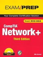
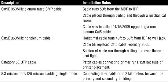
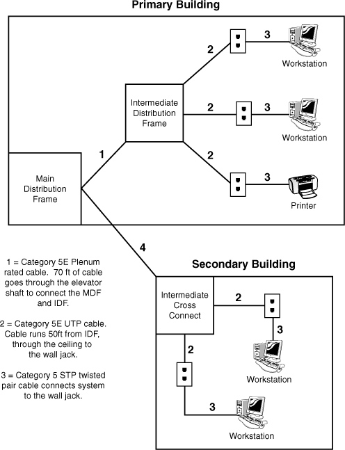
Several types of wiring schematics exist. They can be general, as shown in Figure 13.1, or they can include a detailed schematic reference, as shown in Figure 13.2 and Table 13.1.
Figure 13.1 General wiring schematic.
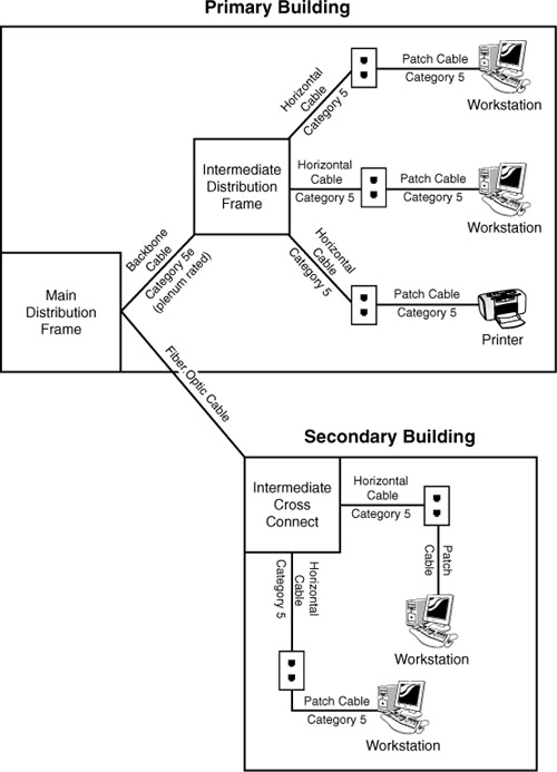
Figure 13.2 Wiring schematic that corresponds to Table 13.1
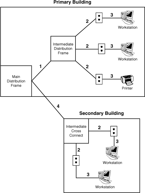
Table 13.1 Wiring Schematic Reference Sample
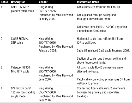
Figure 13.1 and Figure 13.2 provide a simplified look at network wiring schematics. Imagine how complicated these diagrams would look on a network with 1, 2, or even 6,000 computers. Quality network documentation software makes this easier, but still the task of network wiring can be a large one for administrators. When documenting wiring, administrators need to ensure that someone could pick up the diagrams and have a good idea of the network wiring.
You might consider documenting network wiring to be a waste of your time. You might, that is, until you need to troubleshoot some random network problems. Without any network wiring schematics, the task will be frustrating and time consuming. Even with simplified information provided in Figure 13.2 and Table 13.1, it is possible to evaluate the network wiring and make recommendations.
In the hypothetical information provided in Figure 13.2 and Table 13.1, several potential problems exist with the network wiring. Any administrator could walk in and review the network documentation and isolate the potential problems. Now it’s your turn.
Challenge
You have been called in to review the wiring for a company. Reviewing Table 13.2, what potential wiring issues might you be concerned with? What would you recommend?
Table 13.2 Wiring Schematic Reference Sample
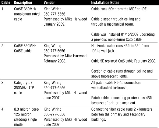
After reviewing the documentation, you recommend the following:
1. Patch cable connectors were attached in-house. Self-made cables can be a trouble spot. Purchasing quality cables with securely attached connectors removes any doubt.
2. The patch cable length going to the printer may be too far. Typically patch cables are no more than 5ft. This is often for safety reasons, such as users tripping over patch cables. Remember, UTP has a run of 100 meters; this includes all cable from patch panel to computer system.
3. Horizontal cable runs through the ceiling and over fluorescent light. May need plenum or STP cable to help manage interference.
4. Backbone cable is not rated sufficiently if run through mechanical rooms or other areas. Typically, backbone cable would be plenum rated. Certainly any cable that runs through most ceilings, mechanical rooms, or elevator shafts should be plenum rated.
Note
Time to update Network wiring schematics are a work in progress. Although changes to wiring do not happen daily, they do occur when the network expands or old cabling is replaced. It is important to remember that when changes occur to the network, the schematics have to be updated to reflect the changes. Out-of-date schematics can be frustrating to work with.
Physical and Logical Network Diagrams
In addition to the wiring schematics, documentation should also include diagrams of the physical and logical network design. Recall from Chapter 1, “Introduction to Networking,” network topologies can be defined on a physical level or a logical level. The physical topology refers to how a network is physically constructed—that is, how it looks. The logical topology refers to how a network looks to the devices that use it—in other words, how it functions.
Network infrastructure documentation won’t be reviewed daily; however, this documentation is essential for someone unfamiliar with the network to manage or troubleshoot the network. When it comes to documenting the network, you need to document all aspects of the infrastructure. This includes the physical hardware, physical structure, protocols, and software used.
Physical Network Documentation
The physical documentation of the network would include such elements as
• Cabling information—A visual description of all the physical communication links, including all cabling, cable grades, cable lengths, WAN cabling, and so on.
• Servers—The physical network diagram would include the server names and IP addresses, types of servers, and domain membership.
• Network devices—The physical diagram must include the location of the devices on the network. This would include the printers, hubs, switches, routers, gateways, and so on.
• Wide area network—The physical network also includes the location and devices of the WAN network and components.
• User information—The diagram may include some user information, such as the number of local and remote users.
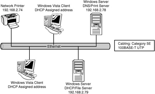
Figure 13.3 shows a diagram of a physical segment of a network.
Networks are dynamic and changes can happen regularly. The physical network diagrams have to be updated as well. Organizations have different policies and procedures on how often updates should occur. A general rule is that the diagram should be updated whenever significant changes are made to the network, such as the addition of a bridge, change in protocols, or the addition of a new server. These changes impact how the network operates, and the documentation should reflect the changes.
Exam Alert
Document change Documentation should be updated periodically and each time a major change is made to the network. This includes the addition of hardware or setting changes.
Logical Network Documentation
The logical network refers to the direction that data actually flows on the network within the physical topology. The logical diagram is not intended to focus on the hardware of the network but rather how data flows through that hardware. In practice, the physical and logical topologies can be the same. In the case of the bus physical topology, data travels along the length of the cable from one computer to the next. So, the diagram for the physical and logical bus would be the same. Figure 13.4 shows the physical and logical bus.
Figure 13.4 Physical and logical bus topology.
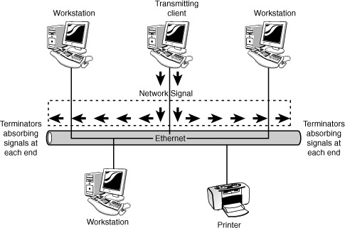
This is not always the case. For example, a topology can be in the physical shape of a star, but data is passed in a logical ring. The function of data travel is performed inside a switch in a ring formation. So the physical diagram would appear to be a star, but the logical diagram shows data flowing in a ring formation from one computer to the next. Simply put, looking at a physical diagram it is difficult to tell the way in which data is flowing on the network.
In today’s network environments, the star topology is a common network implementation. Ethernet uses a physical star topology but a logical bus topology. In the center of the physical ethernet star topology is a hub or switch. What happens inside this switch defines the logical bus topology. The switch passes data between ports as if they were on an ethernet bus segment.
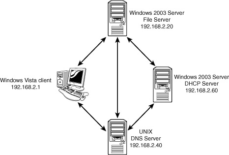
In addition to data flow, logical diagrams may include additional elements, such as the network domain architecture, server roles, protocols used, and so on. Figure 13.5 shows how a logical topology may look in the network documentation.
Figure 13.5 Logical topology diagram.
Exam Alert
Logical topology The logical topology of a network identifies the logical paths that data signals travel over the network. Remember this for the Network+ exam.
Baselines
Baselines play an integral part in network documentation because they provide the capability to monitor the overall performance of the entire network. In simple terms, a baseline is a measure of performance that indicates how hard the network is working and where network resources are being spent. The purpose of a baseline is to provide a basis for comparison. For example, you can compare the performance results of the network taken in March to one taken in June, or from one year to the next. More commonly, you would compare the baseline information at a time when the network is having a problem to information recorded when the network was operating with greater efficiency. Such comparisons help you determine if, in fact, there has been a problem with the system, such as degrading performance, and how significant that problem is and how it impacts users.
To be of any use, baselining is not a one-time task; rather, baselines should be taken periodically to be able to provide an accurate comparison. You should take an initial baseline after the network is set up and operational and then again when major changes are made to the network. Even if no changes are made to the network, periodic baselining can prove useful as a means to determine whether the network is still operating correctly.
All network operating systems (NOS), including Windows, MAC OS, UNIX, and Linux have built-in support for network monitoring. In addition many third-party software packages are available for detailed network monitoring. The system-monitoring tools provided in a NOS give you the means to take performance baselines for either the entire network or an individual segment within the network. Because of the different functions of these two baselines, they are referred to as a system baseline and a component baseline.
To create a network baseline, network monitors provide a graphical display of network statistics. Network administrators can choose a variety of network measurements to track and use these statistics to perform routine troubleshooting tasks, such as locating a malfunctioning network card, a downed server, or a denial of service (DoS) attack.
Collecting network statistic information is a process referred to as capturing. Administrators can capture statistics on all elements of the network. For baseline purposes, one of the most common statistics to monitor is bandwidth usage. By reviewing bandwidth statistics, administrators can see where the bulk of network bandwidth is being used. Then administrators can adapt the network for bandwidth use. If too much bandwidth is being used by a particular application, administrators can actively control its bandwidth usage. Without comparing baselines, however, it is difficult to see what is normal network bandwidth usage and unusual network bandwidth use.
Exam Alert
Baselines Remember for the Network+ exam that to provide an effective comparison, baselines need to be performed under the same conditions. If not, the results are not trustworthy.
Policies, Procedures, Configurations, and Regulations
Well-functioning networks are characterized by policies, procedures, and documented configurations. Policies, procedures, and configurations are unique to every network, so every organization should have clear documentation for their network.
Policy Documentation
By definition, policies refer to an organization’s documented rules regarding what is to be done, or not done, and why. Policies dictate who can and cannot access particular network resources, server rooms, backup tapes, and so on.
Although networks may have different policies, depending on their needs, some common policies include the following:
• Network Usage Policy—This policy specifies who can use network resources such as PCs, printers, scanners, and remote connections. In addition to stating who can use these resources, the usage policy dictates what can be done with these resources after they are accessed. For example, the policy might state that no outside systems will be networked without permission from the network administrator.
• Internet Usage Policy—This policy specifies the rules for Internet use on the job. Typically, usage should be primarily focused on business-related tasks. The policy might state that incidental personal use is allowed during specified times.
• Email Usage Policy—This policy emphasizes that email must follow the same code of conduct as expected in any other form of written or face-to-face communication. All emails are property of the company and can be accessed by the company. Personal emails should be erased right away.
• Personal Software Policy—This policy outlines what software, if any, users can load onto the network or personal computer. These policies typically dictate that no outside software should be installed on network computer systems. All software installations must be approved by the network administrator.
• User Account Policy—This policy typically states that users are responsible for keeping their password and account information secret. All staff are required to log off their systems when they are finished using them. Attempting to log on to the network with another user account is considered a serious violation.
• Ownership Policy—This policy typically states that the company owns all data, including email, voicemail, and Internet usage logs, of users and reserves the right to inspect these at any time.
This list is just a snapshot of the policies that guide the behavior for administrators and network users. Network policies should be clearly documented and available to network users. Often, these policies are reviewed with new staff members or new administrators. Policies are reviewed and updated regularly. As they are updated, they are rereleased to network users.
Exam Alert
Policy making For the Network+ exam, remember that network policies dictate network rules and provide the guidelines for network conduct.
Network Procedure Documentation
Network procedures differ from policies in that they identify the way in which tasks are to be performed. For example, each network administrator has backup procedures identifying the time of day backups are done, how often they are done, and where they are stored. A number of procedures apply to networks for practical reasons but perhaps more importantly for security reasons.
Administrators have to be aware of several procedures when on the job. The number and exact type of procedure depends on the network, the organization, or even the network administrator. The overall goal of the network is to ensure uniformity and ensure that network tasks follow a framework. Without this procedural framework, different administrators may approach tasks differently and cause confusion on the network.
Network procedures may include the following:
• Backup procedures—These procedures identify how all backups are to be performed, who can perform them, and who can use them for recovery purposes. It may also include the types of backup such as full, incremental, or differential, and at what frequency these backup types are done. So the backup policy may dictate that a full backup is to be done Monday evenings with incremental backups done Wednesdays, Thursdays, and Fridays.
• Procedures for adding new users—When new users are added to a network, administrators typically have to follow certain guidelines to ensure that users have access to what they need but no more. One such procedure may include the principle of lease privilege. This states that users are assigned the minimum privileges to do their jobs—nothing more, nothing less.
• Security procedures—Some of the more critical procedures involve security. These procedures identify security monitoring, security researching, and applying security updates, as well as what the administrator must do in the event of security breaches.
• Network monitoring procedures—The network needs to be constantly monitored. This includes reviewing such things as bandwidth, application errors, network operating system updates, and the like.
• Software procedures—All software needs to be monitored and updated periodically. Documented procedures dictate when, how often, by whom, and why these updates are done.
• Procedures for reporting violations—From time to time, users do not follow outlined network policies. This is why documented procedures should exist to handle the violations properly. These policies may include a first verbal warning followed by written reports and account lockouts.
• Remote access procedures—Many workers access the network remotely. This remote access is granted and maintained using a series of defined procedures. These may dictate the time remote users can access the network, how long they can access, and what they can access.
These represent just a few of the policies administrators must follow on the job. It is important that all of these procedures are documented well and are accessible. To be effective, all network procedures must be reviewed and updated as needed.
Configuration Documentation
Another critical form of documentation is configuration documentation. Many administrators think they could never forget the configuration of a router, server, or switch, but it happens more often than not. Although it’s often a thankless, time-consuming task, documenting the network hardware and software configurations is critical for continued network functionality.
Two primary types of network configuration documentation are required: software documentation and hardware documentation. Both types of documentation include all configuration information so that should a computer or other hardware fail, both the hardware and software can be replaced and reconfigured. The documentation is important because often the administrator who configured the software or hardware is not available, and someone else has to re-create the configuration using nothing but the documentation. To be effective in this case, the documentation has to be as current as possible. Older configuration information may not help.
Regulations
The terms regulation and policy are often used interchangeably; however, there is a difference. As previously mentioned, policies are written by an organization for its employees. Regulations are actual legal restrictions with legal consequences. These regulations are not set by the organizations but by applicable laws in the area. The following is an example of network regulations:
Transmission, distribution, uploading, posting or storage of any material in violation of any applicable law or regulation is prohibited. This includes, without limitation, material protected by copyright, trademark, trade secret or other intellectual property right used without proper authorization, material kept in violation of state laws or industry regulations such as social security numbers or credit card numbers, and material that is obscene, defamatory, libelous, unlawful, harassing, abusive, threatening, harmful, vulgar, constitutes an illegal threat, violates export control laws, hate propaganda, fraudulent material or fraudulent activity, invasive of privacy or publicity rights, profane, indecent or otherwise objectionable material of any kind or nature. You may not transmit, distribute, or store material that contains a virus, “Trojan Horse,” adware or spyware, corrupted data, or any software or information to promote or utilize software or any of Network Solutions services to deliver unsolicited email. You further agree not to transmit any material that encourages conduct that could constitute a criminal offense, gives rise to civil liability or otherwise violates any applicable local, state, national or international law or regulation.
Exam Alert
Regulations are the law For this exam and in real-life networking, remember that regulations are often enforceable by law.
Monitoring the Network to Identify Performance
When networks were smaller, and few stretched beyond the confines of a single location, network management was a simple task. In today’s complex, multisite, hybrid networks, however, the task of maintaining and monitoring network devices and servers has become a complicated but essential part of the network administrator’s role. Nowadays, the role of network administrator often stretches beyond the physical boundary of the server room and reaches every node and component on the network. Whether an organization has 10 computers on a single segment or a multisite network with several thousand devices attached, the server administrator has to be able to monitor all network devices, protocols, and usage—preferably from a central location.
Given the sheer number and diversity of devices, software, and systems on any network, it is clear why network management is such an important consideration. Despite the fact that a robust network management strategy can improve administrator productivity and reduce downtime, many companies choose to neglect network management because of the time involved in setting up the system or because of the associated costs. If these companies understood the potential savings, they would realize that neglecting network management could lead to a huge monetary loss.
Network management and network monitoring are essentially methods to control, configure, and monitor devices on a network. Imagine a scenario in which you are a network administrator working out of your main office in Spokane, WA, and you have satellite offices in New York, Dallas, Vancouver, and London. Network management allows you to access systems in the remote locations or have the systems notify you when something goes awry. In essence, network management is about being able to see beyond your current boundary and being able to act on what you see.
Network management is not one thing. Rather, it’s a collection of tools, systems, and protocols that, when used together, provide the capability to perform tasks such as reconfiguring a network card in the next room or installing an application in the next state.
Note
IDS and IPS The objectives included in this chapter identified IPS and IDS. However, these topics are included in Chapter 14, “Network Access Security,” with a discussion of firewalls.
The capabilities demanded from network management vary somewhat among organizations, but essentially, several key types of information and functionality are required, such as fault detection and performance monitoring. Here are some of the types of information and functions that network management tools can provide:
• Fault detection—One of the most important aspects of network management is knowing if anything is not working or is not working correctly. Network management tools can detect and report on a variety of faults on the network. Given the number of devices that constitute a typical network, determining faults without these tools could be an impossible task. Additionally, network management tools may have the capability to not only detect the faulty device but also shut it down. This means that if a network card is malfunctioning, you can disable it remotely. When a network spans a large area, fault detection becomes even more invaluable because it allows you to be alerted to network faults and to manage them, thereby reducing downtime.
• Performance monitoring—Another feature of network management is the ability to monitor the performance of the network. Performance monitoring is an essential consideration that provides you with some crucial information. Specifically, performance monitoring can provide network usage statistics and user usage trends. This type of information is essential when you’re planning network capacity and growth. Monitoring performance also helps you to determine if any performance-related concerns exist, such as whether the network can adequately support the current user base.
Note
Performance monitoring Performance monitoring can be included with baselines. For more information on this, see the preceding baseline section.
• Security monitoring—Any good server administrator has a touch of paranoia built into his or her personality. A network management system provides the capability to monitor who is on the network, what they are doing on the network, and how long they have been doing it. What’s more important, in an environment where corporate networks are increasingly exposed to outside sources, the ability to identify and react to potential security threats is a priority. Reading log files to learn of an attack is a poor second to knowing that an attack is currently in progress and being able to react accordingly.
• Remote management and configuration—Want to reconfigure or shut down the server that is located in Australia? Remote management and configuration are key parts of the network management strategy, enabling you to manage huge multisite locations centrally.
Many tools are available to help monitor the network and ensure that the entire network is functioning properly. Some tools, like the packet sniffer, can be used to monitor traffic for administrators and those wanting to obtain data that doesn’t belong to them. In this section we look at several monitoring tools.
Packet Sniffers
Packet sniffers are commonly used on networks. They are either a hardware device or software that basically eavesdrops on transmissions that are traveling throughout the network. The packet sniffer quietly captures and saves data to be reviewed at a later time. Packet sniffers can also be used on the Internet to capture data traveling between computers. Internet packets often have very long distances to travel, going through various servers, routers, and gateways. Anywhere along this path, packet sniffers can quietly sit, collecting data. The information obtained from packet sniffers can be used by network administrators to isolate bottlenecks, identify throughput usage, test whether data packets are secure, and so on. However, as much as the information is useful for network administrators, the same information can be useful to hackers. In this way, the packet sniffer can be used for good or for not so good. It depends on who is using it.
It is those using packet sniffers against you that keep network administrators up at night. You have two key defenses against packet sniffers being used maliciously on your network. The first is to use a switched network, which most today are. In a switched network, data is sent from one computer system and direct from the switch only to intended targeted destinations. In an older network using traditional hubs, the hub does not switch the traffic to an isolated user; rather, it sends traffic to all users connected to the hub’s ports. This shotgun approach to network transmission makes it easier to place a packet sniffer on the network to obtain data.
The second approach is to ensure that all sensitive data is encrypted as it travels. Ordinarily, encryption is used when data is sent over a public network such as the Internet, but it may also be necessary to encrypt sensitive data on the LAN. Encryption can be implemented in a number of ways; for example, connections to web servers can be protected using the Secure Sockets Layer (SSL) protocol and HTTPS. Communications to mail servers can also be encrypted using SSL. For public networks, the IPsec protocol can provide end-to-end encryption services.
You learn more about encryption protocols in Chapter 14.
Throughput Testing
In the networking world, throughput refers to the rate of data delivery over a communication channel. In this case, throughput testers test the rate of data delivery over a network. Throughput is measured in bits per second (bps), for example, 10Mbps. Administrators need to be aware of exactly what the network is doing, so testing throughput is important. It may be that a high-speed network is not functioning with the expected level of throughput, and bottlenecks occur. Testing throughput is done periodically or after any large changes to the network, such as the installation of a new networkwide application or new server.
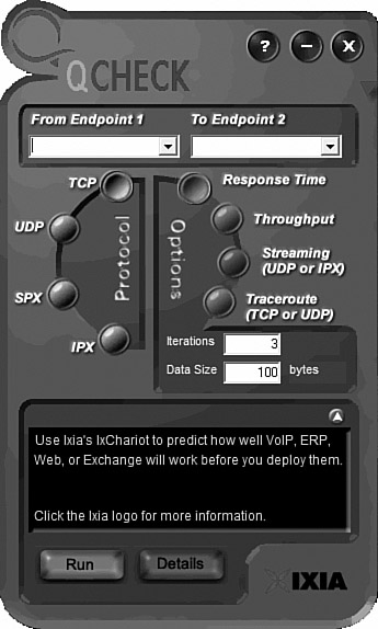
Any throughput tester is designed to quickly gather information about the network’s functionality, and specifically, the average overall network throughput. Many software-based throughput testers are available online, both for free and for a fee. Figure 13.6 shows a software-based throughput tester.
Figure 13.6 Software throughput tester.

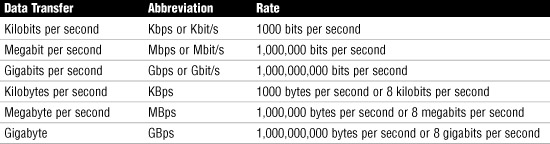
As shown in Figure 13.6, throughput testers do not have to be complicated to be effective. To use it, enter the beginning point and then the destination point. The tester will send a predetermined number of data packets to the destination and report on the throughput level. A throughput tester identifies how long it takes to send the data to the destination point and receive acknowledgment that the data was received. The results are displayed in Kbps or Mbps. Table 13.3 shows the various data rate units.
Administrators can periodically conduct throughput tests and keep them on file to create a picture of network performance. If it is suspected that a problem exists with the network functionality, the administrator can compare a test with past performance to see exactly what is happening.
The terms throughput and bandwidth are often used interchangeably, but in fact there is a difference. When we talk about measuring throughput, we are measuring the amount of data flow under real-world conditions. That is, measuring with possible EMI influences, heavy traffic loads, improper wiring, and even network collisions. Take all this into account, take a measurement, and you have the network throughput. Maximum bandwidth, on the other hand, refers to the amount of information that is possible to be sent through a particular media under ideal conditions.
Exam Alert
Know the difference For the Network+ exam, be sure you know the difference between throughput and bandwidth.
Port Scanners
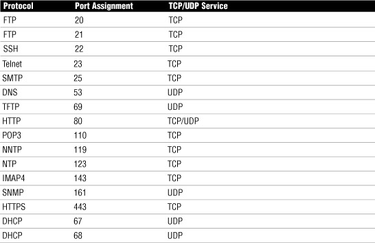
A port scanner is a software-based security tool designed to search a network host for open ports on a TCP/IP based network. As a refresher, in a TCP/IP based network, a system can be accessed through one of 65536 available port numbers. Each network service is associated with a particular port. Table 13.4 shows some common protocols and associated ports.
Table 13.4 Some of the Most Common TCP/IP Suite Protocols and Their Port Assignments
Exam Alert
Ports For the Network+ exam, be sure you can identify the ports used by the more common TCP/IP protocols.
These are just a few of the available ports, and the ports we would expect to be open and available. Many of the thousands of other ports are closed by default; however, many others, depending on the OS, are open by default. These are the ports that can cause us trouble. Like packet sniffers, port scanners can be used both by administrators and by hackers. Hackers use port scanners to try to find an open port that they can use to access a system. Port scanners are easily obtained on the Internet either for free or for a modest cost. After they are installed, the scanner probes a computer system running TCP/IP looking for a UDP or TCP that is open and listening.
When a port scanner is used, several ports states may be reported:
• Open/Listening—The host sent a reply indicating that a service is listening on the port. There was a response from the port.
• Closed or Denied or Not Listening—No process is listening on that port. Access to this port will likely be denied.
• Filtered or Blocked—There was no reply from the host, meaning that the port is not listening or the port is secured and filtered.
Note
For your protection Sometimes an ISP will take the initiative, often blocking specific traffic entering their network before it reaches their customers, or after leaving their customers before it exits their network. This is done to protect customers from well-known attacks.
Because hackers can potentially review the status of our ports, it is important that administrators are aware which ports are open and potentially vulnerable. As previously mentioned, many tools and utilities are available for this. The quickest way to get an overview of the ports being used by the system and their status is to use the issue the netstat –a command from the command line. A sample of the printout from the netstat –a command and active connections for a computer system is shown in Listing 13.1. The output from a Windows XP system may look a little different, but the information would be the same.
Listing 13.1 Output from a netstat –a Command from a Windows Vista System
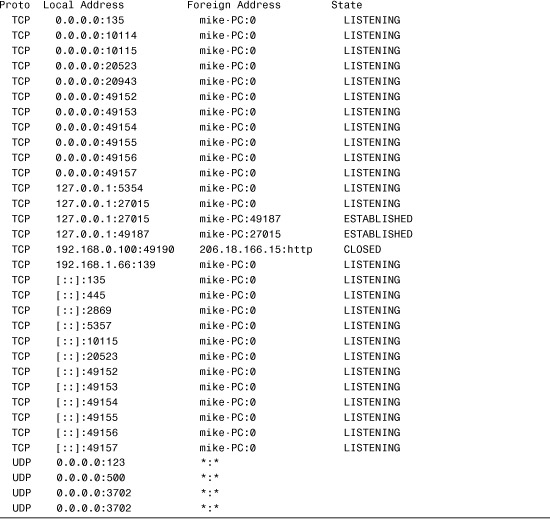
As you can see from Listing 13.1, the system has many listening ports. Not all of these suggest that a risk exists, but it does let us know that they might be vulnerable. To test for actual vulnerability, we use a port scanner. As an example, we can use a free online scanner to probe the system. Many free online scanning services are available. Although a network administrator may use these free online tools for curiosity, for real security testing, a quality scanner should be used.
Note
Scan your system To find out more about pot scanners and to conduct an online scan of your computer system, go to grc.com and use their Shieldsup! utility.
Exam Alert
Port scanning For the Network+ exam, remember that port scans identify closed, open, and listening ports and can be used by those intending on compromising security by finding open and unguarded ports.
Network Testing
When testing the network, administrators often perform three distinct types of tests: performance, load, and stress tests. These test names are sometimes used interchangeably, but although some overlap exists, they are different types of network tests, each with different outcome goals in mind.
Performance Testing
A performance test is, as the name suggests, all about measuring the current performance level of the network. The goal is to take ongoing performance tests and evaluate and compare them, looking for potential bottlenecks. For performance tests to be effective, they need to be taken under the same type of network load each time, or the comparison is not valid. That is, a performance test taken at 3:00 a.m. is going to be different from one taken at 3:00 p.m.
Exam Alert
Performance testing On the Network+ exam, be prepared to identify the goal of performance testing, which is to establish baselines for the comparison of network functioning.
Load Testing
Load testing has some overlap with performance testing. Sometimes called volume or endurance testing, load tests involve artificially placing the network under a larger workload. For example, the network traffic may be increased throughout the entire network. After this is done, performance tests can be done on the network with the increased load. Load testing is sometimes done to see if there are bugs in the network that are not currently visible but that may become a problem as the network grows. For example, a company’s mail server may work fine with the current network load, but if the network grew by 10%, the increased load may overwhelm the server. Load tests are all about finding a potential problem before it happens.
Performance tests and load tests are quite similar; however, the information outcomes are different. Performance tests identify the current level of network functioning for measurement and benchmarking purposes. Load tests are designed to give administrators a look into the future to determine if the current network infrastructure can handle the load.
Exam Alert
Load or performance For the Network+ exam, be prepared to identify the difference between performance and load tests. Specifically, performance test are about the network functioning today, whereas load tests look forward to see if performance may be hindered in the future by growth or other changes to the network.
Stress Testing
Finally, we have stress testing. Whereas load tests do not try to break the system under intense pressure, stress tests sometimes do. They are used to push resources to the limit. Although these tests are not done often, they are necessary and, for administrators at least, entertaining. There are two clear goals of stress testing: the first is to see exactly what the network can handle. That is, where is its breaking point, which is useful to know in terms of network expansion. Second, stress testing allows administrators to test their backup and recovery procedures. If a test knocks network resources out, administrators can verify that their recovery procedures work, and the test allows them to observe network hardware failure. Stress tests assume that someday something will go wrong, and administrators will know exactly what to do when it happens.
Logging
In a network environment, all NOSs and most firewalls, proxy servers, and other network components have logging features. These logging features are essential for network administrators to review and monitor. Many types of logs can be used. In this section we review four of the most common: system, security, history, and event logs.
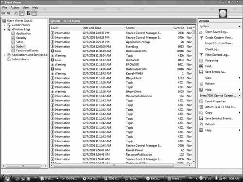
On a Windows server system, as with the other operating systems, events and occurrences are logged to files for later review. Windows server and desktop systems such as Vista/XP and 2000 use the Event Viewer to view many of the key log files. The logs in Event Viewer can be used to find information on, for example, an error on the system or a security incident. Information is recorded into key log files, although you will also see additional log files under certain conditions, such as if the system is a domain controller or is running a DHCP server application.
Security Logs
A system security log contains events related to security incidents, such as successful and unsuccessful logon attempts and failed resource access. Security logs are customizable, meaning that administrators can fine-tune exactly what they want to monitor. Some administrators choose to track nearly every security event on the system. Although this may be prudent, it often can cause huge log files that are too large and take up too much space. Figure 13.7 shows a security log from a Windows system.
Figure 13.7 Windows security log.

Notice in Figure 13.7 that there were some successful logons and logoffs. In a potential security breach, there would be some audit failures for logon or logoff attempts. To save space and prevent the log files from growing too big, administrators may choose to audit failed logon attempts, not successful ones.
Each event in a security log contains additional information to make it easy to get the details on the event. To do this, double-click any events listed in the security log. Additional information includes the following:
• Date—The exact date the security event occurred.
• Time—The time the event occurred.
• User—The name of the user account that was tracked during the event.
• Computer—The name of the computer used when the event occurred.
• Event ID—The type of event that has occurred. This ID can be used to get additional information about the particular event. Events can be anything from a logon on to logoff to a tracked OS crash.
To be effective, security logs should be reviewed regularly.
Application Logs
Application logs contain information logged by applications that run on a particular system and not just the operating system itself. Vendors of third-party applications can use the application log as a destination for error messages generated by their applications.
The application log works in much the same way as the security log. It tracks events within applications—both successful events and failed events. Figure 13.8 shows the details provided from an applications log.
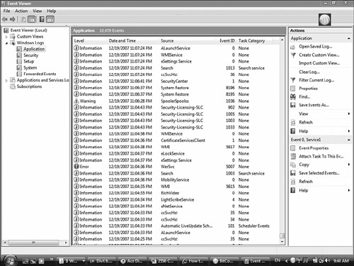
Notice in Figure 13.8 that three types of events occurred: general application information events, a warning event, and an error event. Vigilant administrators would likely want to check the event ID of both the event and warning failures to isolate the cause.
System Logs
System logs record information about components or drivers in the system. This is the place to look when you’re troubleshooting a problem with a hardware device on your system or a problem with network connectivity. For example, messages related to the client element of DHCP appear in this log. The system log is also the place to look for hardware device errors, time synchronization issues, or service startup problems. Figure 13.9 shows an example of a system log.
History Logs
History logs are most often associated with the tracking of Internet surfing habits—that is, log files that maintain a record of all sites that a user visits. Network administrators may review these for potential security or policy breaches, but generally these are not commonly reviewed.
Another form of history logs are a compilation of events from other log files. For instance, one history log may contain all significant events over the past year from the security log on a server. History logs are critical because they provide a detailed account of alarm events that can be used to track trends and locate problem areas in the network. This information can help you revise maintenance schedules, determine equipment replacement plans, and anticipate and prevent future problems.
Note
Log files Application logs, history logs, and system logs can often be viewed by any user. Security logs can be viewed only by users who are using accounts with administrative privileges.
Log Management
Monitoring logs can require significant time and effort. That is where Log Management (LM) strategies come into play. LM describes the process of managing large volumes of system-generated computer log files. LM includes the collection, retention, and disposal of all system logs. LM can be completely designed in-house or you can use many third-party LM applications that are designed to make the whole process easier. Whichever way you go, LM can be a huge task. It is essential to ensure the proper functioning of the network and applications and keep an eye on network and system security.
Configuring our systems to log all sorts of events is the easy part; trying to find the time to review the logs is an entirely different matter. To help with this process, third-party software packages are available to help with the organization and reviewing of log files.
Networking Tools
A large part of network administration involves having the right tools for the job and knowing when and how to use them. Selecting the correct tool for a networking job sounds like an easy task, but network administrators can choose from a mind-boggling number of tools and utilities.
Given the diverse range of tools and utilities available, it is unlikely that you will encounter all the ones available or even all those discussed in this chapter. For the Network+ exam, however, you are required to have a general knowledge of the tools and what they are designed to do.
Until networks become 100% wireless, network administrators can expect to spend some of their time using a variety of media-related troubleshooting and installation tools. Some of these tools, such as the tone generator and locator, may be used for troubleshooting media connections, and others, such as wire crimpers and punchdown tools, are used to create network cables and connections.
Note
Basic tool Although many costly, specialized networking tools and devices are available to network administrators, the most widely used tool—the standard screwdriver—costs only a few dollars. As a network administrator, you can expect to take the case off a system with amazing regularity—to replace a network interface card (NIC) or perhaps remove the cover from a hub to replace a fan. Advanced cable testers and specialized tools will not help you when you need a screwdriver.
Wire Crimpers
Wire crimpers are tools you might use regularly. Like many things, making your own cables can be fun at first, but the novelty soon wears thin. Basically, a wire crimper is a tool that you use to attach media connectors to the ends of cables. For instance, you use one type of wire crimper to attach RJ-45 connectors on unshielded twisted-pair (UTP) cable, and you use a different type of wire crimper to attach Bayonet Neill Concelman (BNCs) to coaxial cabling. Figure 13.10 shows an example of a wire crimper for crimping both RJ-11 and RJ-45 connectors.
Figure 13.10 A wire crimper for RJ-45 and RJ-11 cables. (Photo courtesy of TRENDware International, www.trendware.com.)

Tip
Cable caveat When making cables, always order more connectors than you need; there will probably be a few mishaps along the way.
In a sense, you can think of a wire crimper as a pair of special pliers. You insert the cable and connector separately into the crimper, making sure that the wires in the cable align with the appropriate connectors. Then, by squeezing the crimper’s handles, you force metal connectors through the wires of the cable, making the connection between the wire and the connector.
When you crimp your own cables, you need to be sure to test them before putting them on the network. It only takes a momentary lapse to make a mistake when creating a cable, and you can waste time later trying to isolate a problem in a faulty cable.
Strippers and Snips
Two other commonly used wiring tools are strippers and snips. Wire strippers come in a variety of shapes and sizes. Some are specifically designed to strip the outer sheathing from coaxial cable, and others are designed to work best with UTP cable. Any type of strippers are designed to cleanly remove the sheathing from wire to make sure a clean contact can be made.
Many administrators will not have specialized wire strippers unless they do a lot of work with copper-based wiring. However, standard wire strippers are good to have on hand.
Wire snips are tools designed to cleanly cut the cable. Sometimes network administrators will buy cable in bulk and use wire snips to cut the cable in desired lengths. The wire strippers are then used to prepare the cable for the attachment of the connectors.
Punchdown Tools
Within network wiring closets are rows of distribution blocks, or patch panels. A patch panel is a freestanding or wall-mounted unit with a number of RJ-45 connections on the front. The patch panel provides a connection point between network equipment such as hubs and switches and the ports to which PCs are connected, which are normally distributed throughout a building.
The individual wires within a twisted pair cable need to be attached to the back of the patch panel for each RJ-45 connector slot. This is where a punchdown tool is used. The punchdown tool presses each of the individual wires within the twisted-pair cable into the connectors at the back of the patch panel. The metal connectors in which the wires are pressed are known as insulation displacement connectors (IDCs). See Figure 13.11.
Figure 13.11 A punchdown tool. (Photo courtesy of TRENDware International, www.trendware.com.)

A discussion of punchdown tools and how they are used is provided in Chapter 2, “Media and Connectors.”
Cable Certifiers
Today’s networks are all about speed, and for good reason. Whereas the original networks were used to share simple files and resources such as printers, today’s networks see the convergence of voice, data, and video applications on a single network. To accommodate these applications, higher-performance cabling solutions are required to maintain the high demands placed on them. Many existing networks are being retrofitted to meet the demands of high-bandwidth applications.
The question for network administrators is, can the existing wiring infrastructure meet the current and future demands of network users? This is where cable certifiers come into the picture. Cable certifiers can be used to determine cable fault locations, cable length issues, cable noise problems, and qualify cables for applications such as VoIP. These handheld devices create a full summary of the cable test results, allowing administrators to see exactly if the current cabling can meet the demands of network users.
Some of the common features of cable certifiers include the following:
• The capability to test telephone and coax cables for continuity and proper termination.
• Determine cable length and distances.
• Verify twisted-pair integrity including opens, shorts, miswires, split pairs, and so on.
• Identify individual cable runs to locate and identify routes
• Obtain accurate reflection of cables’ ability by measuring NEXT, FEXT, attenuation, and return loss and bit error rates to determine cable carrying capability.
Exam Alert
Certifiers For the Network+ exam, remember that certifiers test the speed of cables, ensuring they can meet the demands of network applications.
Voltage Event Recorders
Voltage event recorders are used to monitor the quality of power used on the network or by network hardware. Voltage event recorders are used to identify potential power-related concerns such as power sags, spikes, surges, or other power variations. Such power irregularities can cause problems for hardware and, in the case of serious spikes, can destroy hardware. Voltage event recorders are attached directly to a wall socket to monitor power. They record their findings, which are reviewed by the administrator.
Temperature Monitors
When we talk about temperature monitoring, we are often referring to the temperature of our server and network equipment rooms. In general, the heat tolerance range for computer equipment is surprisingly wide. Take, for example, a typical server system, which can happily operate in a range between 50°F and 93°F. That is a spread of 43°, which is plenty of room in a normal heated environment. The problem is that if you maintain a computer room at either the upper or lower end of these levels, the equipment will run, but for how long, no one knows.
Although no specific figures exist relating to the recommended temperature of server rooms, the accepted optimum is around 55 to 65°F. At this temperature, the equipment in the room should be able to operate, and those working in the room should not get too cold. Human beings generally require a higher temperature than computer equipment does, which is why placing servers in an office space with staff is not ideal.
Many people assume that the biggest problem with servers and network equipment is that of overheating. To some extent, this is true; servers in particular do generate a great deal of heat and so can overheat to the point where components fail. But this is only one of the heat-related issues. A more significant, and more gradual, problem is that of temperature consistency.
Heat causes components to expand, and cooling causes them to contract. This is known as thermal expansion and contraction. Even the slightest temperature shifts cause the printed circuit boards and chips to shift around, and if they shift too much or too often, the chance of them becoming separated from their connections is greatly increased. Keeping the heat at a moderate and constant level reduces the expansion and contraction of the boards and increases the reliability of the components.
Note
Close doors Never wedge open a door to an environmentally controlled room, no matter how cold you get. Not only does having an open door defeat the purpose of the controlled environment, but it can also damage air conditioning units.
One way administrators keep their equipment rooms at the right temperature is using temperature monitors. In the equipment room, temperature monitors constantly document changes in room temperature. If the monitor detects radical changes in temperature, it sends an alert to the administrator. This can sometimes occur if someone leaves a door open to the server room, if the air conditioning breaks, or if some piece of network hardware is producing a lot of heat. Although network temperature monitors may not often be needed, having them installed adds great peace of mind for administrators.
Toner Probes
A toner probe, also called toner and probe, are two devices that can save a network installer many hours of frustration. There are two components to this tool: the tone generator and the tone locator. In the field, you might hear the tone generator and the tone locator referred to as the fox and hound.
The purpose of the toner and probe is to generate a signal that is transmitted on the cable you are attempting to locate. At one end, you press the tone locator against individual wires; at the other, the tone generator sends a signal down a specific cable. When the tone locator makes contact with the wire that has the tone generators signal on it, the locator emits an audible signal or tone.
The toner and probe is a useful device, but it does have some drawbacks. First, it often takes two people to operate—one at each end of the cable. Of course, one person could just keep running back and forth; but if the cable is run over great distances, this can be a problem. Second, using the tone generator is time consuming because it must be attached to each cable independently.
Note
Labeling cables Many problems that can be discovered with a tone generator are easy to prevent by taking the time to properly label cables. If the cables are labeled at both ends, you will not need to use such a tool to locate them.
Exam Alert
Toners For the Network+ exam, remember that the toner and probe are specifically used for locating the ends of cables hidden in floors, ceilings, or walls, and tracking cables from the patch panel to their destination.
Protocol Analyzer
Protocol analyzers can be hardware or software based; their primary function is to analyze network protocols such as TCP, UPD, HTTP, FTP, and so on. In use, protocol analyzers will help diagnose computer networking problems, alert you of unused protocols, identify unwanted or malicious network traffic, and help isolate network traffic-related problems.
Like packet sniffers, protocol analyzers capture the communication stream between systems. But unlike the sniffer, the protocol analyzer also reads and decodes the traffic. Decoding allows the administrator to view the network communication in English. From this, administrators can get a better idea of the traffic that is flowing on the network. When unwanted or damaged traffic is spotted, analyzers make it easy to isolate and repair. For example, if a problem occurs with specific TCP/IP communication, such as a broadcast storm, the analyzer can identify the source of the TCP/IP problem and isolate the system causing the storm. Protocol analyzers also provide many statistical and real-time trend statistics that help for management justification of new hardware.
Protocol analyzers can be used for two key reasons:
• Identify protocol patterns—By creating a historical baseline of its analysis, administrators can spot trends for protocol errors. That way, when a protocol error occurs, it can be researched to see if that error has occurred before and what was done to fix it.
• Decode information—Capturing and decoding network traffic allows administrators to see what exactly is going on with the network on a protocol level. This helps identify protocol errors as well as potential intruders.
Exam Alert
Statistics For the Network+ exam, remember that protocol analyzers allow administrators to examine the bandwidth that a particular protocol is using.
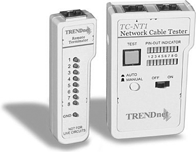
Media/Cable Testers
A media tester, also called a cable tester or continuity tester, defines a range of tools designed to test whether a cable is working properly. Any tool that facilitates the testing of a cable can be deemed a cable tester. However, there are specific tools called media testers and continuity testers. These media testers allow administrators to test a segment of cable, looking for shorts, improperly attached connectors, or other cable faults. All media testers inform you whether or not the cable is working correctly and where the problem in the cable may be. Continuity testers are designed to verify that an electrical path exists between two end points. In the network, this means continuity between your cable jack and termination point. Continuity testers can locate shorts or other wiring problems in a section of network cabling. Figure 13.12 shows an example of a media tester. Note that there are two parts to the media tester: one for each end of the cable.
Figure 13.12 An example of a media tester. (Photo courtesy of TRENDware International, www.trendware.com.)
Media Testers
Although network administrators will not need to use a cable tester every day, it could significantly help in the troubleshooting process. This section describes time domain reflectometers (TDR), which are used on copper cables, and optical time domain reflectometers (OTDR), which are used on optical cables. You also learn about multimeters.
TDR
A time domain reflectometer (TDR) is a device used to send a signal through a particular media to check the continuity of the cable. Good quality TDRs have the capability to locate many types of cabling faults, such as a severed sheath, damaged conductors, faulty crimps, shorts, loose connectors, and the like. TDRs help ensure that data sent across the network is not interrupted by poor cabling that may cause faults in data delivery.
Exam Alert
TDR For the Network+ exam, you should know that TDRs work on the physical layer of the OSI model, sending a signal through a length of cable looking for cable faults.
OTDR
Because the majority of network cabling is copper based, most tools designed to test cabling are designed for copper-based cabling. However, when you test fiber-optic cable, you need an optical tester.
An optical cable tester performs the same basic function as a wire media tester, but on optical media. The most common problem with an optical cable is a break in the cable that prevents the signal from reaching the other end. Because of the extended distances fiber-optic cables can cover, degradation is rarely an issue in a fiber-optic LAN environment.
Ascertaining whether a signal reaches the other end of a fiber-optic cable is relatively easy, but when you determine that a break exists, the problem becomes locating the break. That’s when you need a tool called an optical time-domain reflectometer (OTDR). By using an OTDR, you can locate how far along in the cable the break occurs. The connection on the other end of the cable might be the source of the problem, or perhaps there is a break halfway along the cable. Either way, an OTDR can pinpoint the problem.
Unless you work extensively with fiber-optic cable, you’re unlikely to have an OTDR or even a fiber-optic cable tester in your toolbox. Specialized cabling contractors will have them, though, so knowing they exist is important.
Multimeter
One of the simplest cable-testing devices is a multimeter. By using the continuity setting, you can test for shorts in a length of coaxial cable; or, if you know the correct cable pinouts and have needlepoint probes, you can test twisted-pair cable.
A basic multimeter combines several electrical meters into a single unit offering the capability to measure voltage, current, and resistance. Advanced models can also measure temperature.
A multimeter has a display, terminals, probes, and a dial to select various measurement ranges. A digital multimeter has a numeric digital display, whereas an analog one has a dial display. Inside a multimeter, the terminals are connected to different resistors depending on the range selected.
Network multimeters can do much more than test electrical current. Look for multimeters to do the following:
• Ping specific network devices—A multimeter can ping and test response times of key networking equipment such as routers, DNS servers, DHCP servers, and so on.
• Verify network cabling—It is possible to use a network multimeter to isolate cable shorts, split pairs, or other faults.
• Locate and ID cable—Quality network multimeters allow administrators to locate cables at patch panels and wall jacks using digital tones.
• Document findings—Multimeter results can be downloaded to a PC for inspection. Most network multimeters provide a means to link to a PC, such as USB ports.
Network Qualification Tester
The network qualification tester gives administrators a quick glance at the network’s bandwidth and whether in its current configuration it can grow to support VoIP or Gigabit Ethernet.
If a network is running slow, the network qualification tester can identify why the network is struggling. For example, it can identify cross talk within a cable and how it is impacting the network performance. Most quality network qualification testers can test twisted-pair and coaxial cable, and other models test for fiber-optic cable.
Exam Alert
Qualification testing Remember for the Network+ exam, network qualification testers allow administrators to identify the current speeds the network cabling can support and isolate cabling from network problems.
Butt Set
A butt set is most often associated with telephony, but it can be used on some data networks as well. A butt set allows the administrator or technician to butt or tap into a communication line and use it. In the case of a phone line, a technician can use the line normally—that is, make a call, answer a call, or listen into a call.
The butt set looks somewhat like a regular phone handset with wires attached. The wires from the handset connect to the phone wire and that’s it. The technician can test and access the phone line. This device can be used to test network telephony but has limited use on network cable. Some network butt sets allow the access of data on the cable, but many other tools can do the same thing with better results.
Wireless Detector
Wireless media requires its own types of tools. One such tool is a Wi-Fi detector. The intent of such a device is to reveal Wi-Fi hot spots and detect wireless network access with LED visual feedback. Such devices can be configured to scan specific frequencies. When working with 802.11b/g/n networks, you will most certainly require scanning for 2.4GHz RF signals.
Such devices can be used in the troubleshooting process to identify where and how powerful RF signals are. Given the increase in wireless technologies, RF detectors are sure to increase in popularity. Figure 13.13 shows a Wi-Fi detector.
Figure 13.13 Wireless RF detector.

Summary
This chapter focuses on the cable management and documentation. Documentation is an important part of the administrator’s role. It involves having documentation of network layout, both physical and logical, as well as documented network procedures, policies, configurations, and regulations.
Documentation is not a one-time process; keeping up-to-date documentation is necessary to ensure network functionality. In addition to documenting, administrators must review documentation and log files to ensure that they are aware of any security breaches or other issues on the network.
You can use many software- and hardware-based tools to test the network and help in documentation of the network. These tools include packet sniffers, protocol analyzers, load testers, and throughput testers.
Administrators can use many tools to help maintain and troubleshoot network media. These tools include a TDR, OTDR, cable tester, mulitmeter, toner probe, and butt set. In addition, there are tools you can use to work with media, including snips, strippers, and punchdown tools.
Key Terms
• Butt set
• Cable stripper
• OTDR
• Physical and logical network diagrams
• TDR
• Wireless
Apply Your Knowledge
Exercises
13.1 Testing Network Throughput
In this exercise, you walk through the steps to test the throughput between two points on a network. You download a trial version of a software-based throughput tester and use it to test the connection.
Estimated time: 10 minutes
1. Open your Internet browser and go to the QCheck page on the IxChariot website: www.ixiacom.com/products/display?skey=qcheck.
2. From this screen, click the link that reads Install QCheck.
3. You will be asked to fill out your name and address on a form web page. Then verification will be sent to your email. Click the link in your email to begin the download of the QCheck tester.
4. The installed QCheck throughput tester will resemble Figure 13.14.
Figure 13.14 QCheck throughput tester.
5. With the throughput tester open, select the protocol you wish to test, either UDP or TCP. Select the beginning location and end point IP addresses.
6. Finally, select the brown Throughput button and click the Run button to test the throughput between the two points you selected.
7. To test the difference in performance, try testing the throughput at different times of day. The throughput readouts should vary according to traffic load.
13.2 Diagram Your Network
This exercise assumes you have a home network established or have knowledge of a network design. In this exercise, you document a physical network design.
Estimated time: 10 minutes
1. Open your browser and navigate to the WERESC website at http://www.weresc.com/network.php.
2. Select the Download link. This will install free network diagram software to your computer, as shown in Figure 13.15.
Figure 13.15 Network diagram software.

3. Using the predrawn elements on the left side of the screen, draw the physical layout of your network.
Exam Questions
1. You have recently installed a new server in a wiring closet. The server shuts down periodically and you suspect there may be power-related problems. Which of the following tools might you use to isolate a power problem?
![]() A. Voltage multimeter
A. Voltage multimeter
![]() B. Voltage regulator
B. Voltage regulator
![]() C. Voltage monitor
C. Voltage monitor
![]() D. Voltage event recorder
D. Voltage event recorder
2. While you were away, an air conditioning unit malfunctioned in a server room and the room and some equipment overheated. Which of the following would have alerted you to the problem?
![]() A. Multimeter
A. Multimeter
![]() B. Temperature monitor
B. Temperature monitor
![]() C. TDR
C. TDR
![]() D. OTDR
D. OTDR
3. Which of the following involves pushing the network beyond its limits, often downing the network to test network limits and recovery procedures?
![]() A. Crash and burn
A. Crash and burn
![]() B. Stress test
B. Stress test
![]() C. Recovery test
C. Recovery test
![]() D. Load test
D. Load test
4. You have been given a physical wiring schematic. The schematic shows the following:
Given this information, what cable recommendation might you make if any?
![]() A. Nonplenum cable should be used between the IDF and MDF.
A. Nonplenum cable should be used between the IDF and MDF.
![]() B. Horizontal cable run should use plenum cable.
B. Horizontal cable run should use plenum cable.
![]() C. Patch cable connecting printer should be shorter.
C. Patch cable connecting printer should be shorter.
![]() D. Leave network cabling as is.
D. Leave network cabling as is.
5. What tool would you use when working with an IDC?
![]() A. Wire crimper
A. Wire crimper
![]() B. Media tester
B. Media tester
![]() C. OTDR
C. OTDR
![]() D. Punchdown tool
D. Punchdown tool
6. As a network administrator, you find yourself working in a wiring closet where none of the cables have been labeled. Which of the following tools are you most likely to use to locate the physical ends of the cable?
![]() A. Toner probe
A. Toner probe
![]() B. Wire crimper
B. Wire crimper
![]() C. Punchdown tool
C. Punchdown tool
![]() D.
D. ping
7. Which of the following commands can be issued from the command line to view the status of the systems ports?
![]() A.
A. netstat -p
![]() B.
B. netstat -o
![]() C.
C. netstat –a
![]() D.
D. netstat -y
8. You suspect that an intruder has gained access to your network. You want to see how many failed logon attempts there were in one day to help determine how they got in. Which of the following might you do?
![]() A. Review the history logs.
A. Review the history logs.
![]() B. Review the security logs.
B. Review the security logs.
![]() C. Review the logon logs.
C. Review the logon logs.
![]() D. Review the performance logs.
D. Review the performance logs.
9. You have been called into to inspect a network configuration. All your customer has for reference is a single network diagram. Considering the diagram, which of the following statements are true?
Figure 13.16 Network wiring schematic.
![]() A. Cable 1 does not need to be plenum rated.
A. Cable 1 does not need to be plenum rated.
![]() B. Cable 2 should be STP cable.
B. Cable 2 should be STP cable.
![]() C. Cable 3 is incorrect, STP cannot be connected directly to a wall jack.
C. Cable 3 is incorrect, STP cannot be connected directly to a wall jack.
![]() D. Cable 2 goes beyond recommended length.
D. Cable 2 goes beyond recommended length.
![]() E. The network looks good from this diagram.
E. The network looks good from this diagram.
10. You are installing a new system into an existing star network and need a cable that is 45 feet long. Your local vendor does not stock cables of this length, so you are forced to make your own. Which of the following tools will you need to complete the task?
![]() A. Optical tester
A. Optical tester
![]() B. Punchdown tool
B. Punchdown tool
![]() C. Crimper
C. Crimper
![]() D. UTP splicer
D. UTP splicer
11. Which of the following network utilities are used by both hackers and administrators to eavesdrop on network transmissions?
![]() A. Port filters
A. Port filters
![]() B. Packet filters
B. Packet filters
![]() C. Data watchers
C. Data watchers
![]() D. Packet sniffers
D. Packet sniffers
12. You are troubleshooting a problem with a workstation and have managed to narrow it down to a single patch cable. What tool might you use to troubleshoot the problem further?
![]() A. Tone generator/locator
A. Tone generator/locator
![]() B. OTDR
B. OTDR
![]() C.
C. ping
![]() D. Media tester
D. Media tester
13. You have recently been informed that 75 new users will be added to the network over the next two months. You are concerned about the impact on overall network functionality. Which of the following could you do to verify that the network can handle the load?
![]() A. Stress test
A. Stress test
![]() B. Performance test
B. Performance test
![]() C. Load test
C. Load test
![]() D. Traffic test
D. Traffic test
14. What tool can be used to find a break in a length of fiber-optic cable?
![]() A. Tone generator
A. Tone generator
![]() B. TDR
B. TDR
![]() C. OTDR
C. OTDR
![]() D. Fox and hare
D. Fox and hare
15. You have been called in to troubleshoot a network that is experiencing intermittent connectivity problems. Which of the following documentation might you request to see first?
![]() A. Security logs
A. Security logs
![]() B. History logs
B. History logs
![]() C. Physical network diagram
C. Physical network diagram
![]() D. Logical network diagram
D. Logical network diagram
16. Which of the following utilities can measure voltage, current, and resistance?
![]() A. Multimeter
A. Multimeter
![]() B. TDR
B. TDR
![]() C. OTDR
C. OTDR
![]() D. Toner probe
D. Toner probe
17. A toner probe is sometimes referred to as what?
![]() A. Fox and rabbit
A. Fox and rabbit
![]() B. Fox and hare
B. Fox and hare
![]() C. Fox and hound
C. Fox and hound
![]() D. Fox and dog
D. Fox and dog
18. Which of the following describes network procedures?
![]() A. Legally enforceable rules.
A. Legally enforceable rules.
![]() B. Series of rules established by an organization.
B. Series of rules established by an organization.
![]() C. They identify the way in which network tasks are to be performed.
C. They identify the way in which network tasks are to be performed.
![]() D. They identify the way in which policies are to be followed.
D. They identify the way in which policies are to be followed.
19. Your network server maintains several key applications that are shared to all systems on the network. Recently users have been complaining that the application is running slowly and sometimes they can’t access it at all. Which of the following might you do first?
![]() A. Move the server closer to the client stations.
A. Move the server closer to the client stations.
![]() B. Review the physical network diagram.
B. Review the physical network diagram.
![]() C. Review the logical logs.
C. Review the logical logs.
![]() D. Review the application logs.
D. Review the application logs.
20. On several occasions, your network server has been compromised and a Trojan horse installed remotely. You suspect someone is gaining access to your system. Which of the following might you do? (Choose all that apply.)
![]() A. Review the history logs.
A. Review the history logs.
![]() B. Use a port scanner.
B. Use a port scanner.
![]() C. Use a packet sniffer.
C. Use a packet sniffer.
![]() D. Use the
D. Use the netstat –a command.
Answers to Exam Questions
1. D. Voltage event recorders are used to monitor the quality of power used on the network or by network hardware. Voltage event recorders are used to identify potential power related concerns such as power sags, spikes, surges, or other power variations. For more information see the section “Voltage Event Recorders” in this chapter.
2. B. Temperature monitors are used in server and network equipment rooms to ensure that the temperature does not fluctuate too greatly. In the case of a failed air conditioner, the administrator would have been alerted of the drastic changes in temperature. Multimeters, TDRs, and OTDRs are used to work with optical based media. For more information, see the “Temperature Monitors” section in this chapter.
3. B. Whereas load tests do not try and break the system under intense pressure, stress tests sometimes do. There are two clear goals of stress testing, the first is to see exactly what the network can handle. That is where is its breaking point which is useful to know in terms of network expansion. Secondly, stress testing allows administrators to test their backup and recovery procedures. For more information, see the section “Network Testing” in this chapter.
4. B. In this scenario, the section of horizontal cable running through the ceiling and over fluorescent lights. This cable run might be a problem as such devices can cause EMI. Alternatively to plenum cable used in this scenario, STP may have worked as well. For more information, see the section “Wiring Schematics” in this chapter.
5. D. You use a punchdown tool when working with an IDC. All the other tools are associated with making and troubleshooting cables, but they are not associated with IDCs. For more information, see the section “Punchdown Tools,” in this chapter.
6. A. The toner probe tool, along with the tone locator, can be used to trace cables. Crimpers and punchdown tools are not used for locating a cable. The ping utility would be of no help in this situation. For more information, see the section “Toner Probes” in this chapter.
7. C. Administrators can quickly determine the status of common ports by issuing the netstat –a command from the command line. This command output will list the ports used by the system and whether they are open and listening. For more information, see the section “Port Scanners” in this chapter.
8. B. The security logs can be configured to show failed or successful logon attempts. In this case, the administrator can review the security logs and failed logon attempts to get the desired information. The failed logs will show the date and time when the failed attempts occurred. For more information, refer to the section “Logging” in this chapter.
9. B. In this diagram, Cable 1 is plenum rated and should be fine. Cable 3’s are patch cable are do not need to be STP rated. However, STP cables can attach directly to the wall jack. Cable 2 however goes through walls and ceilings and therefore it would be recommended to have a better grade of cable than regular UTP. STP provides greater resistance to EMI. In ceilings, lights or other devices can cause interference. For more information, refer to the section “Wiring Schematics” in this chapter.
10. C. When attaching RJ-45 connectors to UTP cables, the wire crimper is the tool you use. When in use, the individual wires from twisted pair cable is inserted into the RJ-45 connector. Once carefully inserted, the RJ-45 connector is placed into the crimpers. The crimpers force a metal connector to pierce the individual wires and the connections is made. None of the other tools are used in the construction of UTP cable. For more information, see the section “Wire Crimpers” in this chapter.
11. D. Packet sniffers are commonly used on networks. They are either a hardware device or software and eavesdrop on network transmissions that are traveling throughout the network. The packet sniffer quietly captures data and saves to be reviewed at a later time. For more information, see the section “Packet Sniffers” in this chapter.
12. D. If you suspect a problem with a patch cable, you can use a media tester to test it. An OTDR is used to test optical cables, and so it would not be used on UTP, which is copper-based cable. The other tools discussed in this question would not be used. For more information, see the section “Media Testers” in this chapter.
13. C. A load test allows administrators to put the network and specific network hardware under increased loads to test their functionality. In this case the number of users on the network is due to grow. The administrator can run a load test to see what impact the new users will have on the network. A simulated load test will reveal potential problems before the new user are added. For more information see the section “Load Testing” in this chapter.
14. C. An OTDR can be used to find a break in a length of fiber-optic cable. The other tools listed cannot be used to troubleshoot a break in a fiber-optic cable. For more information, see the section “OTDR” in this chapter.
15. C. In this case, there are intermittent transmission problems that may be related to cables being used and cable placement. If you were able to see a physical network diagram you may notice that the wrong cable type is being used. Reviewing the logical diagram might be done after verifying that the physical one looked ok. It would not necessarily help in this case to review security or history logs. For more information on networking tools, refer to the section on “Physical and Logical Network Diagrams” in this chapter.
16. A. A basic multimeter combines several electrical meters into a single unit offering the ability to measure voltage, current and resistance. Advanced models can also measure temperature. A multimeter has a display, terminals, probes and a dial to select various measurement ranges. A digital multimeter has a numeric digital display, while an analogue has a dial display. Inside a multimeter, the terminals are connected to different resistors depending on the range selected. For more information refer to the section “Multimeter” in this chapter.
17. C. A toner probe is sometimes referred to as the fox and hound. None of the other answers are valid. A toner and probe is used to locate the ends of a cable, the toner probe generates a signal that is transmitted on the wire you are attempting to locate. At the other end, you press the tone locator against individual wires. When it makes contact with the wire that has the signal on it, the locator emits an audible signal or tone. For more information, see the section “Toner Probes” in this chapter.
18. C. Network procedures differ from policies in that they identify the way in which tasks are to be performed. For example, each network administrator has backup procedures identifying the time of day backups and done, how often they are done, and where they are stored. A network is full of a number of procedures both for practical reasons but perhaps more importantly for security reasons. Policies are established rules from a particular organization. For more information see the section “Policies, Procedures, Configurations, and Regulations” in this chapter.
19. D. The application log contains information logged by applications that run on a particular system rather than the operating system itself. Vendors of third-party applications can use the application log as a destination for error messages generated by their applications. In this case it would be necessary to review the application logs on the server to determine the problems with the application. For more information, see the section “Application Logs” in this chapter.
20. B, D. For security reasons, administrators must know what ports are open and potentially accessible from outside sources. Some ports are left open by default in operating systems making them vulnerable to outside attack. Port scanners provide a way to check the status of all system ports ensuring that they cannot be compromised. Additionally, the netstat –a command can be used on Windows systems to quickly identify the status of the systems ports. For more information, see the section “Port Scanners” in this chapter.