
02
Air 
Definition:
Air: The Mixture of Matter in Gaseous and Vapour State of Which the Earth’s Atmosphere is Composed
Air is fundamental for human survival: without air or, more accurately, without oxygen, we suffocate and die. We can also be poisoned by other gases, and by small particles present in air (if the concentrations are high enough). Outdoors (and away from sources of pollution) where the air consists of the standard mixture of gases there is no question of having the right balance of gases. But inside buildings, human beings and their activities result in higher levels of harmful gases, water vapour and pollutants – including the products of combustion, toner gases from photocopiers and even unpleasant odours.
The need to ensure a suitable air supply is not restricted to building occupants: many space and water heating appliances require oxygen for combustion. There are also conditions in which the building fabric needs to be properly ventilated.
Until recently, much of the air supply for the building occupants and for combustion appliances was provided by what was euphemistically referred to as ‘fortuitous ventilation’: that is, the infiltration of air through gaps and cracks in the fabric. Such air movement is usually inefficient (resulting in heat loss as warmed air is replaced by cold external air) and often uncomfortable (producing uneven internal temperatures and draughts).
We need to design buildings which have an adequate air supply and are also energy efficient and comfortable. That requires an understanding of the behaviour of gases and the broader influences of the earth’s atmosphere and the forces which can affect the structure of buildings, but can also be used to drive the ventilation of buildings.
This chapter considers the requirements of an air supply for the wellbeing of building occupants, as well as the effects of air supply on the building fabric. It also considers the various ventilation strategies available to designers. Throughout the chapter we will keep in mind the interactions between air – particularly in ventilation – and heat and moisture.
The fundamentals of air
In order to understand the behaviour of air in and around buildings we need to consider how gases behave as their temperatures and pressures change, and how that in turn affects the movement of air in the earth’s atmosphere. Then we need to examine how that movement, in the form of wind, produces forces which act on the surfaces and structures of buildings. Finally, we will look at how air movement within a building is produced by differences in air pressure and temperature, including the stack effect.
The behaviour of gases
Gas is one of the four states of matter: the atoms and molecules in gases move freely and are separated by much greater distances than those of solids and liquids. Despite that separation there are constant collisions between gas particles and between the particles and adjacent surfaces. The force of those collisions exerts a pressure within the gas and on those surfaces. Pressure is measured in pascals (Pa), but when dealing with atmospheric pressure we usually work in kilopascals (kPa), which are a thousand times larger. Atmospheric pressure is also measured in bar, equivalent to 100 kPa, and millibar, equivalent to 100 Pa.
The pressure exerted by a quantity of gas is affected by its volume and temperature (see Figure 2-01): heating a fixed amount of any gas increases the internal energy of the molecules, which will either result in an increase in volume (expansion) as the molecules move further away from each other or, if expansion is not possible (because the gas is contained) an increase in pressure. Conversely, cooling the gas will reduce either the volume or the pressure. As the pressure and temperature of a gas are connected, it is often necessary to look at the behaviour at a standard temperature and pressure (STP). Usually this is 0ºC and 100 kPa.
The relationships between the volume, temperature and pressure of a gas are predicted by the gas laws. In conditions close to STP most gases conform closely to the gas laws and their behaviour is easy to predict, but at higher temperatures and lower pressures their behaviour diverges from the laws.
Where there is a mix of gases – as there is in the earth’s atmosphere – each gas in the mixture exerts part of the pressure; this is known as its partial pressure. The total pressure exerted by the gas mixture is the sum of the partial pressures of all the gases in it. Where there is water vapour present in the gas mixture, the total pressure is the sum of the gas pressure and the water vapour pressure.
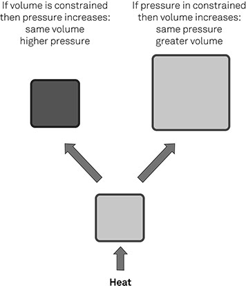
Figure 2-01
The Relationship between Temperature, Volume and Pressure
Variations in air temperature and pressure result in air moving from areas of high pressure to low pressure: that occurs on a large scale in the earth’s atmosphere, and on a smaller scale in and around buildings.
The earth’s atmosphere and the weather
The lowest layer of the earth’s atmosphere – the troposphere – extends approximately 12 km from the surface of the earth and exerts a pressure on the earth which is roughly equivalent to the weight of the air above it. Atmospheric pressure is greatest at sea level and decreases with altitude, and is affected by temperature and humidity. Differences in atmospheric pressure result in winds, as air moves from higher to lower pressure areas.
Large-scale wind patterns are affected by topography, as mountains and valleys produce variations in wind direction and speed. At a smaller scale, sea breezes at coasts change direction according to the relative temperatures of sea and land during diurnal cycles of warming and cooling. The operation of all these forces produces the climatic conditions that act upon a building, including wind, rainfall and, to some extent, temperature.
Wind action
When wind blows onto a building the air is mainly deflected around it, producing different air pressures across the building, with high pressures on the windward face and lower pressures on the other faces (Figure 2-02). The pressure differentials result in forces acting on the fabric of the building, usually referred to as wind loads, and also in pressure differences between the inside and outside which can drive natural ventilation (see: Natural ventilation p. 61).
The pressure differences, and therefore the wind loads, are determined by the speed of the wind and its direction, and the orientation and configuration of the building relative to the wind. The presence of the building will also affect the wind forces experienced around the building, in some cases creating strong air currents that affect pedestrians.
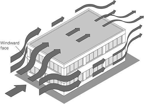
Figure 2-02
Air Currents Produced by the Wind Blowing across a Building
Wind speed
As the speed of the wind at a site constantly varies, wind speeds are quoted as standardised speeds for a height of 10 m above ground blowing across open country. That standardised wind speed is then adjusted to site conditions, taking account of:
- * The terrain – effective wind speeds will be lower in urban and suburban areas than rural areas
- * Altitude – wind speeds are generally greater at higher altitudes
- * Position relative to orographic1 features such as hill and escarpments, and proximity to the sea
Wind speed can be expressed in several different ways:
- * Ten-minute mean wind speeds with a 50-year return period (that is, there is a 2% probability of that speed being exceeded in any one year) are used in structural calculations because they express the greatest forces likely to be encountered
- * Mean annual wind speeds are representative of conditions experienced throughout the year and are therefore used in ventilation
For any location, the wind speeds used for structural calculations will be many times greater than those used in ventilation calculations.
Wind direction
The wind speed at a site will vary with the wind direction. The analysis of wind loads and ventilation pressure differences should therefore consider the forces produced when the wind blows from each the eight cardinal wind directions (N, NE, E, SE, S, SW, W, NW). For larger or more sensitive buildings (e.g. a naturally-ventilated commercial building) it may be necessary to calculate forces for every 30º segment.
Most sites have a prevailing wind direction (the direction the wind blows most frequently), which is affected by large-scale weather patterns and local topography. The wind forces produced by the prevailing wind are of particular importance because they represent the commonest conditions the building will experience.
Wind loads and forces
Once the site wind speed has been calculated for eight or twelve directions the air pressures and wind loads acting on the building can be calculated. The methods vary for different types of structure (and for the assessment of ventilation forces), but in outline:
- The wind speed is used to calculate a peak velocity pressure (or the ‘dynamic pressure’, which is effectively the same thing), taking account of turbulence produced by neighbouring buildings, terrain and exposure.
- The peak velocity pressure is multiplied by an external pressure coefficient (Cpe) or an internal pressure coefficient (Cpi) to obtain the pressure on the external or internal surface.
- Finally, the pressure on a surface is multiplied by its area to obtain the wind load on that surface.
The wind forces acting on the building depend on the size and shape of the building and its position relative to the wind direction. Windward surfaces, such as walls facing directly into the wind, will experience positive pressures and therefore positive wind loads, while the sides and leeward faces will experience negative pressures and therefore negative wind loads (that is, suction). This is illustrated in Figure 2-03, which shows the varying intensity of air pressures on the same simple building illustrated in Figure 2-02.
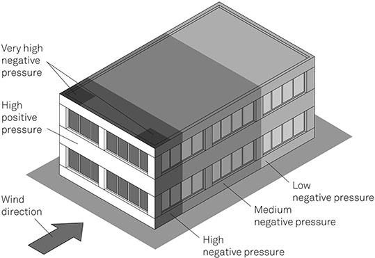
Figure 2-03
Areas of Positive and Negative Pressure Produced by Wind Action on a Building’s Surfaces
The stack effect
The stack effect occurs when a column of air – such as the air in a chimney – is heated. The warmed air expands, becoming less dense, and is displaced upward by colder denser air (the same mechanism of convection; see chapter 1: Mass transport p. 5). The warmed air rises up the column, while colder air is drawn in at the base of the column, producing a current of rising air (Figure 2-04).
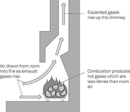
Figure 2-04
The Stack Effect in a Chimney
The stack effect occurs in chimneys and flues, where combustion provides the heat, and in any part of a building in which there is a column of air – for example, a stairwell or atrium – which may be heated by solar gain or gains from the building occupants and their activities, as illustrated in Figure 2-13, p. 64.
The volume of air moved by the stack effect depends on:
- * The stack height – taller stacks generate more air movement because there is a greater pressure difference between the top and bottom of the stack2
- * The temperature difference between the stack (average stack temperature) and outside air – a greater temperature difference results in more air movement, so more air will move during the heating season when the temperature difference is greater, than during the cooling season
- * The free area of openings – larger openings at the top and bottom of the stack will result in a greater volume of air being moved
Air movement in and out of openings on the same side of the building can be produced when internal and external temperatures are different. As Figure 2-05 shows, where the internal temperature is higher, the internal air pressure will be greater than the external air pressure at the top of a space, while the external pressure will be greater at the bottom of the space. As a result, air will move out of the building at the upper opening and into the building at the lower opening. Where the external temperature is greater the air flows are reversed. This phenomenon is one of the drivers of single-sided ventilation (see: Single-sided ventilation p. 46).
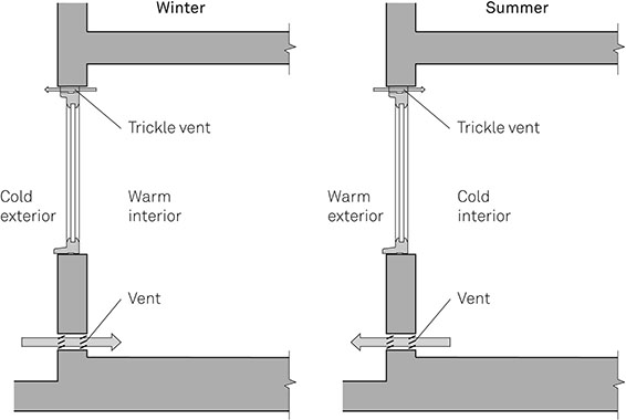
Figure 2-05
Pressure Differences Driving Single-Sided Ventilation
Conditioning the Commons
One of the earliest air conditioning systems – which supplied the temporary House of Commons between 1836 and 1852 – was driven not by mechanical fans but by the stack effect. The system, designed by David Reid, was powered by a large furnace and a tall chimney located adjacent to the chamber of the Commons. The updraught generated by the chimney was used to extract air from the chamber, resulting in fresh air being drawn in through a multitude of small holes in the floor. The chamber could be warmed by passing the incoming air over hot water coils, or cooled by suspending blocks of ice in the air inlets.
The conditions in the temporary House of Commons were vastly superior to those in the previous building, leading one MP to comment: ‘To the skill, zeal and determination of Dr Reid, it is owing that the members of the House of Commons can now pursue their senatorial duties without a sacrifice of health or comfort.’
Air and the building fabric
Wind forces can damage the building fabric;3 they can also result in the infiltration of air through the building fabric with detrimental effects to the comfort of occupants and the energy efficiency of the building. However, there are also conditions where it is necessary to induce air movement in air spaces within building elements to remove high concentrations of moisture or to take advantage of warmed air in the fabric.
The structural effects of wind action
Wind loads on buildings can result in components of the building being dislodged or damaged. Problems most commonly occur on roofs, which are subject to strong suction forces, particularly at perimeters. Fixing specifications for roof coverings should take account of the varying wind loads across the roof (see Figure 2-03 p. 45): the restraints for sheet or membrane coverings must also resist the wind forces acting on layers such as insulation beneath the weatherproofing layer.
Extreme wind forces can produce failure of the building structure, resulting in the collapse of all or part of the building. Although that is uncommon in the UK, there are many parts of the world where extreme weather events, such as hurricanes and tornadoes, do destroy buildings. Although the occurrence of such events is not predictable, it is not wholly random, because the conditions which give rise to them are produced by the large-scale global weather systems (see above: The earth’s atmosphere and the weather p. 43). Tornado Alley gets its name for a reason.
In order to protect occupants, buildings should be designed and constructed to withstand local environmental hazards.
Infiltration
Infiltration is the unintended movement of air between the exterior and interior of a building through the fabric. (Ventilation, by contrast, is the deliberate provision of fresh air, which may be conditioned and the removal of exhaust air.) Infiltration occurs at gaps and cracks in the building fabric, particularly at junctions between building elements and around openings (see Figure 2-06). It is driven by wind action and the stack effect, which can move large amounts of air into and out of buildings, causing draughts which affect user comfort and significant heat loss through mass transfer (see: chapter 1 Mass transfer p. 5).
Until relatively recently, infiltration was included in the overall air supply for a building when assessing the ventilation requirements, However, it is not possible to meet current and future standards of energy efficiency without minimising infiltration and providing the necessary ventilation in a deliberate controlled way. The mantra ‘build tight, ventilate right’ sums up the strategy.
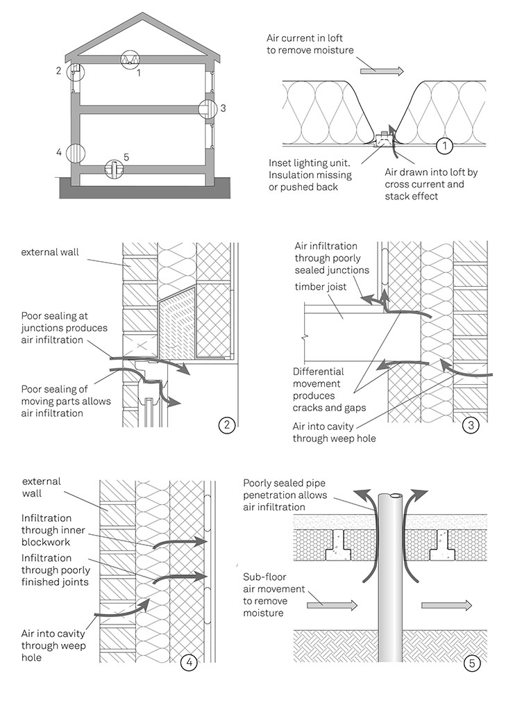
Figure 2-06
Typical Routes for Air Infiltration
Assessing infiltration
The susceptibility a building to air infiltration is expressed by its air permeability, that is, the volume of air which passes through each square metre of its exposed surface in an hour with a pressure difference of 50 Pa between inside and outside. It is expressed as m³/m2.h at 50 Pa (cubic metre per square metre per hour at fifty pascals).
The air permeability is measured by pressure testing, which is carried out using portable fans fitted to a doorway or other opening. The openings of the building are closed and all vents sealed, then the fans are used to raise the air pressure within the building. The rate of air flow generated by the fans is measured at several pressure differences, then the air flow at the standard pressure difference of 50 Pa can be calculated.
The overall rate of air exchange for a building or space is usually given in air changes per hour (ach). One air change per hour notionally represents the replacement of all the air in the space by an equal volume of incoming air. So, 2 ach for a space with a volume of 60 m³ represents the movement of 120 m³ of air. There is no simple relationship between the air permeability rate and ach, because one is based on the area of a building’s envelope and the other on its internal volume.
The rate of air infiltration will depend on the air permeability of the fabric and the environmental conditions, including wind speed and direction, and the internal and external temperatures. Rates vary enormously between buildings: a house built to meet the Passivhaus standard4 requires an air change rate less than 0.6 ach, while in the UK some existing dwellings have air change rates well over 20 ach.
Figure 2-07 shows the reduction in heating energy which can be achieved by reducing air infiltration for a number of building types.
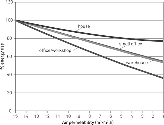
Figure 2-07
The Effect of Infiltration on Heat Loss and Energy Use
Data derived from SAP 2012 for dwellings and iSBEM for non-dwellings
Limiting infiltration
Minimising infiltration requires careful attention to the design and construction of building elements, junctions between elements and service penetrations:
- * Lightweight aggregate blockwork is permeable and requires a parge coat of plaster to seal it. In contrast, structural insulated panels (SIPs) have low permeability because they have large, unbroken sheet facings bonded to insulation, with a limited number of junctions between panels.
- * Cavities within construction should be avoided wherever possible, because introducing a cavity provides a route for air movement.5
- * Junctions between elements should be designed without unnecessary gaps and cavities, and should be sealed, with tapes and sealants matched to the range of differential movement likely to occur. Laps are easier to seal than butt joints.
- * Service penetrations offer significant scope for air leakage, as pipes, ducts and cables often run through elements. The optimum solution is to avoid penetrations wherever possible. Where that is not practicable, penetrations should be properly sealed, particularly at vapour control layers, air barriers and other membranes.
- * Effective sealing of pipework and recessed light fittings is likely to require special components.
‘Breathing’ Buildings
It would seem logical to discuss ‘breathing’ buildings and ‘breathing’ constructions as part of broader consideration of air movement and infiltration; except that when people talk about ‘breathing’ in this context they are usually not talking about air movement, but about moisture transfer through the fabric by diffusion.
Breathing is a physiological process which involves air being drawn into an organism and then expelled. In contrast, a ‘breather membrane’ is a sheet of material with a low vapour resistance (i.e. defined in BS 5250:2011 as less than 0.5 MN/s) which, in the right conditions, facilitates the diffusion of water vapour: it will often be airtight. Clearly, a ‘breather membrane’ does not breathe: neither does a ‘breathing wall’.
It is difficult to identify the source of this terminology, but one of the key references is a leaflet published by the Society for the Protection of Ancient Buildings (SPAB) in 1986, The need for old buildings to ‘breathe’, which gives valuable guidance about problems with trapped moisture within traditional structures and the need to allow moisture transportation by diffusion and evaporation.
Frankly, the use of ‘breathing’ to refer to vapour transfer by diffusion is confusing and is unhelpful when we are attempting to clarify and disentangle the behaviour of air and moisture.
Air in the building fabric
While air infiltration through the building fabric should be avoided, there are situations where air currents are deliberately induced into air spaces to prevent damaging concentrations of moisture (see chapter 3: Moisture and the building fabric p. 83), for example:
- * To the voids beneath suspended floors, in order to prevent ground moisture damaging the floor: this is particularly important for timber floors
- * Behind impervious external layers in constructions, such as sheet metal covering laid on boarding
- * In pitched roofs with vapour resistant underlay and a cold void above the thermal insulation
In each case, moisture moves into the cavity – either from the ground or from the building interior – potentially raising the moisture concentration to harmful levels. The air current replaces the moist air with external air, which should be drier. The air current will also increase the rate of heat loss through the element (see Figure 2-08):
- * The provision of a current of external air effectively isolates the fabric beyond the cavity from the rest of the construction (i.e. the cavity surface acts as the external surface)
- * The air current will increase infiltration by moving air through adjoining layers
- * Where the layer adjacent to the cavity consists of fibrous insulation the pressure differences induced by the air current will result in air exchange between the insulation and the cavity
The simplest way to eliminate these effects is to adopt construction details which do not rely on air currents to avoid problems with moisture (see: chapter 3 Controlling interstitial condensation p. 88). Where that is not possible, for example in refurbishment or heritage projects, the cavity must be isolated from the building interior to limit heat loss.
Beneficial air movement in air spaces
There are three conditions where air currents within air spaces can be thermally beneficial:
- * Dynamic insulation systems for cavity walls – consisting of rigid insulation boards containing vertical channels. Heat moving through the wall from the building interior warms the air within the channels, creating a stack uplift. The warmed air rises to a collector at the top of the wall to be fed directly into the occupied space or used in conjunction with a positive input ventilation system.
- * Transpired solar collectors – consisting of micro-perforated cladding panels with a cavity behind them. The panels are warmed by solar gain, so air drawn through the perforations is also warmed. The air, which is further warmed by heat transferred from the building interior, rises up the cavity and is collected at the top and drawn into the building’s ventilation system.
- * Trombe walls – consisting of thermally massive walls faced with glazed cavities. Solar radiation passes through the glass and is absorbed by the wall, raising its temperature. Unventilated trombe walls rely on conduction to transfer the heat into the occupied space, while ventilated trombe walls have top and bottom vents which allow warmed air from the glazed cavity to reach the occupied space.
Figure 2-08 The Effects of Air Currents in Cavities on Heat Loss in Cold Flat Roof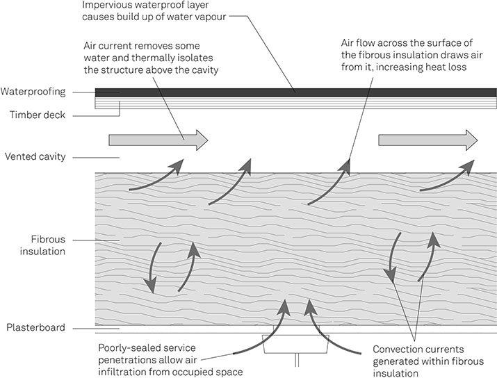
Air and the building occupants
While the primary requirement for air within a building is that it maintains the health and wellbeing of the building occupants, air also affects the operation of some building services – such as combustion appliances used for heating – and has a role in moderating the internal temperature. In addition, in some geographic locations the prevention of the movement of radon gas from the ground to the occupied space is important in protecting building occupants from exposure to radioactivity.
This section examines those requirements for those four aspects of air supply, while the following section discusses ventilation methods.
Air for health and comfort
To protect the health and comfort of building occupants the air supply for a building must:
- * Provide air which is suitable for respiration
- * Remove pollutants (including tobacco smoke)
- * Dilute odours
- * Maintain moisture below nuisance levels
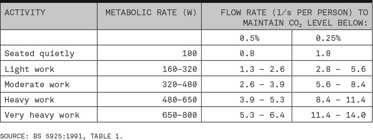
The primary requirement of air for building occupants is that it is suitable for respiration, having the right levels of oxygen and carbon dioxide. The minimum concentration of oxygen for respiration is about 12% at normal atmospheric pressure, while carbon dioxide concentrations should not exceed 0.5%. Expired air contains approximately 16% oxygen and 4% carbon dioxide, so the main challenge when designing a building’s air supply is to provide sufficient fresh air to keep the carbon dioxide concentration below the maximum exposure level, and preferably below 0.25%. The air supply required to maintain those levels varies with the metabolic rate of the building occupants, which is, in turn, proportional to the activity level. Table 2.1 gives typical values. The rate of air flow provided by a ventilation system is usually quoted in litres per second per person (l/s per person). The ventilation rate required for a building or space is typically given in ach (air changes per hour). The air change rate can be combined with the volume of the building to define the rate at which air must be delivered by the ventilation system. Providing suitable air change rates may mean that different ventilation strategies are needed for different parts of the same building. Table 2.1 Air Supply Rates to Limit Carbon Dioxide Levels
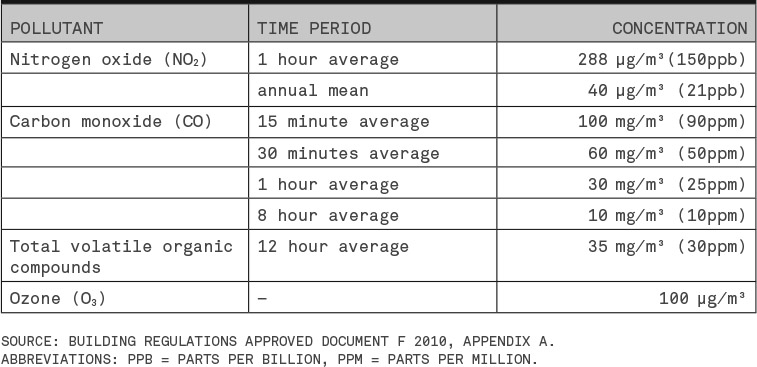
While pollutants such as gases, vapours, dust, fibres and biologically viable material (spores and bacteria) are present in the atmosphere to a varying extent, there are many activities within buildings which can produce pollutants in potentially harmful concentrations. Industrial and manufacturing processes can produce a wide range of pollutants, ranging from dust in sawmills to the emission of volatile chemicals in paintshops; office photocopiers and laser printers emit ozone and volatile organic compounds; underground car parks have high rates of carbon monoxide emission. Table 2.2 gives the UK’s exposure limits for the commonest pollutants. Table 2.2 Maximum Permitted Concentrations of Key Pollutants
Potentially harmful concentrations of pollutants in buildings can be addressed by:
Human beings are sensitive to a wide range of airborne odours; some pleasant, some unpleasant. Within buildings people are subject to many odours, including body odour, toilet odour and cooking odour, with the mix largely dependent on the function of the building. The perception of odours, together with their intensity and quality – and whether or not they are acceptable – rests with individuals and cannot be measured directly. Moreover, the perception of an odour – pleasant or unpleasant – changes over time. Sensitivity lessens over the first half an hour of exposure; over weeks and months it may come to be regarded as normal. The ventilation rates required to address unpleasant odours are therefore based on the perception of someone coming into the space from outside. For spaces where the occupants are mainly sedentary a rate of 10 l/s per person will be sufficient (presuming the space to be a no-smoking zone). Tobacco smoke requires specific consideration, because it is both unpleasant and harmful: it causes irritation of mucous membranes in the respiratory system and eyes, while longer term exposure increases susceptibility to respiratory problems and, of course, lung cancer. Air supply levels to counteract tobacco smoke have been based on considerations of odour for a non-smoker entering a space where smoking is permitted. A rate of 15 l/s per person is recommended for a space with typical number of smokers, rising to 40 l/s where all occupants are assumed to be smokers. The ventilation rates required to avoid mucous membrane irritation are approximately a quarter to a half of the rates for odour control. Bans on smoking in public places and work places means that the need to provide ventilation for smoking is not as significant as 20 or 30 years ago.6 High moisture levels in buildings can adversely affect comfort, induce problems that have an adverse impact on health, such as mould growth and house dust mites, and damage the building fabric (see chapter 3: Moisture and the building fabric p. 83). Water vapour forms part of the air within a building, so the main mechanism by which moisture travels is air movement. Moisture levels may be controlled by drawing moisture-laden air out of the building as close as possible to the point of generation (e.g. in bathrooms, or laundry/cooking areas), while introducing drier air from elsewhere in the building. The necessary rate of air flow will depend on the rate of moisture generation (see chapter 3: Human activity p. 80). The consideration of each aspect of air supply for the health and comfort of building occupants results in a range of requirements for minimum rate of air flow: the requirements for respiration being the lowest and the requirements for the control of odours being the highest. In practice, providing the air supply necessary for the control of odours will meet most of the other requirements. The exceptions, where a higher air supply rate may be required, are:
Respiration
Pollution
Odours
Smoking
Moisture levels
Setting air supply rates
Air for combustion
Combustion appliances, such as heating boilers and cookers, require a supply of oxygen for combustion and their exhaust gases have to be removed.
The air supply for combustion will depend on the type, size and fuel of the appliance, but is likely to be in the range of 0.4–30 l/s for each kilowatt of rated output. For appliances which draw combustion air from the room, the ventilation requirement is commonly expressed in terms of a free area of vent (the total unobstructed opening area of the vent), or the equivalent area (the area of a single opening which would provide the same air flow as the vent, taking into account the effect of air turbulence at vent openings). An insufficient air supply can lead to harmful levels of carbon monoxide (defined in table 2.2).
For appliances with flues or chimneys, the exhaust gases (including carbon monoxide and carbon dioxide) will be drawn up the flue and expelled as a result of the stack effect. No further ventilation provision is required. The exhaust gases from unflued appliance, such as gas cookers and gas heaters, must be removed or diluted by ventilation to maintain concentrations below hazardous levels. The main requirement is to keep carbon dioxide levels in the space below 0.5%.
Balanced flue appliances, which draw air directly from outside and expel exhaust gases outside, such as domestic gas boilers, have no impact on the air supply to the rest of the building, although their exhaust flues, like any other, must be sited away from air intake vents.
Air for moderating temperature
Air movement has a role in moderating the internal temperature of buildings. When the internal temperature rises above the external temperature – as a result of solar gain, metabolic gains and gains from appliances – the warmed air within the building may be extracted and replaced by a supply of cooler air. Depending on the ventilation strategy (see below: Ventilation p. 60) the cooler air may be fresh, external air or conditioned air which has been cooled and perhaps de-humidified. The effectiveness of such cooling depends on the air change rate (which will be constrained by the need to avoid discomfort from air currents (see below: Air currents p. 68), the volume of the space and the relative temperatures of the internal surfaces and outside air.
Air movement can also be used during the night to absorb the heat that has been stored in thermally massive structures and PCMs during the day. Drawing cooler external air through the building, and bringing it into contact with those parts of the structure with higher admittances will transfer heat from the fabric to the air, leaving the fabric able to absorb heat again in the course of the following day.
The rate of air flow provided for cooling the building is likely to exceed that required to maintain the health and wellbeing of building occupants.
Protecting building occupants from radioactivity
Radioactivity, or radioactive decay, is the process in which atoms of unstable isotopes give off charged particles and decay to another element. The charged particles are referred to as ionising radiation because they carry enough energy to strip electrons from atoms they encounter, leaving the atoms with a positive electric charge. Radioactivity is measured in becquerel (Bq): 1 Bq is defined as one transformation or decay per second.
Ionising radiation damages human tissue. For instance, alpha particles emitted during radioactive decay are highly ionising and particularly harmful when ingested or inhaled. They damage lung cells by creating free radicals and damage DNA, which can produce cancerous mutations.
Although any exposure to ionising radiation brings an increased risk of harmful effects, the probability of harm from long-term, low-level exposure is proportionate to the extent of exposure.
The main natural source of radioactivity on earth is radon, a gas formed as part of the decay chain of uranium-234. Radon-222 is carcinogenic when inhaled: it decays in the lungs, emitting alpha particles, and the decay products, which include polonium, are deposited on lung tissue, where they decay further. Radon is the second highest cause of lung cancer in the UK, resulting in 1,100 deaths per year.7
Radon gas occurs naturally in the ground below buildings. It is formed in the geological strata, and rises through faults in the rock to reach the ground surface. It decays to other elements within a few days, so the concentration of radon diminishes rapidly from the source of generation.
The typical outdoor concentration of radioactivity from radon is 10–20 Bq/m3.
Radon rising under a building will collect and penetrate the fabric. The air pressure in buildings is usually slightly lower than that outside, so the under-pressure will draw radon into the building. Also, radon is heavier than air, and the relatively sheltered conditions inside the building can result in high concentrations of radon. Figure 2-09 shows typical routes for radon penetration. Radon is colourless and odourless so the building occupants will not be able to detect it.
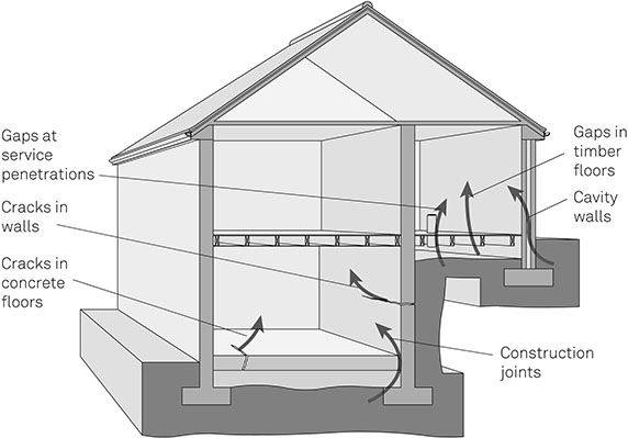
Figure 2-09 Routes of Radon Penetration into Buildings
Based on BR 211:2007, Figure 1
Although any exposure to radon brings a risk of harm, an indoor radon concentration of 200 Bq/m3 is recognised by the World Health Organization as the level at which radon protection measures are necessary in dwellings. In much of the UK the action level of 200 Bq/m3 is accompanied by a target level of 100 Bq/m3, at which radon protection should be considered.8
For new buildings, the radon concentration cannot be measured directly at the design stage, so the need for protective measures is established by consulting radon maps, which in the UK are prepared by the British Geological Survey. The maps show those areas where there is a significant likelihood of a dwelling having a radon concentration above the action level. Radon is particularly prevalent in areas with higher concentrations of uranium, such as those with granite-based geology (e.g. the Lake District and Cornwall).
Radon concentrations in existing buildings can be established by measurement. The standard method is to use passive detectors to record the amount of radioactivity taking place over a three to six month period.
Radon protection measures are commonly divided into passive measures, used at lower risk levels, and active measures used at higher risk level.
New buildings – passive protection measures
Passive measures limit the transmission of radon from the ground to the occupied space. They commonly involve the installation of a radon-resistant membrane, typically low-density polyethylene (LDPE), across the entire footprint of the building as far as the outside face of the external walls. (This is sometimes referred to as a radon barrier.) The construction details will vary, but groundbearing concrete floors, such as that shown in Figure 2-10, can incorporate a gas-resistant membrane between the slab or deck and the screed.
New buildings – active protection measures
Where higher concentrations of radon are likely, ventilation is required below the radon-resistant membrane to draw radon from beneath the building and reduce the pressure of radon against the underside of the membrane.
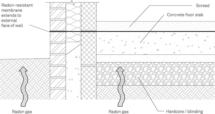
Figure 2-10 Passive Radon Protection Measures on a Groundbearing Concrete Floor
Providing ventilation beneath a suspended floor is straightforward, as shown in Figure 2-11. Groundbearing floors will require collection chambers, referred to as radon sumps, which are vented to the atmosphere: pre-fabricated plastic sumps are commonly used.
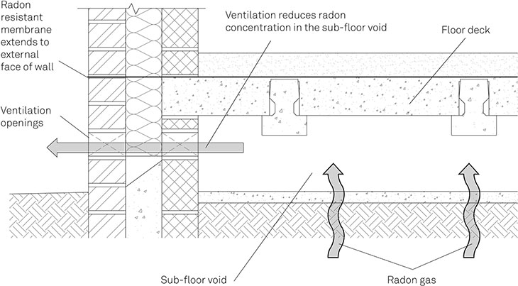
Figure 2-11
Active Radon Protection Measures for a Suspended Floor
Active systems should include provision for retro-fitting of an extraction system (mechanical or passive stack) which can be installed if high radon concentrations were to be found inside the building after construction.
Existing buildings
It is rarely possible to fit a radon-resistant membrane to an existing building. Remedial measures are therefore designed to:
- * Reduce radon pressure beneath the floor – by fitting a radon sump under a solid floor or by increasing the amount of ventilation beneath a suspended floor. A radon sump can be formed from the outside by making a hole in the external wall below ground level, digging out a small cavity beneath the floor, then fitting an extract pipe which discharges at roof level. The best results are obtained with fan-powered systems.
- * Prevent radon reaching the building interior – by installing positive pressure ventilation which forces air into the building and eliminates the normal under-pressure which draws radon into the building. Sealing gaps and cracks in floors can also reduce radon transmission, but may result in the decay of timber floors;
- * Remove radon from the interior – by increasing ventilation rates. This will only be of limited benefit.
Ventilation
Having considered the factors that determine the air supply requirements, we can now consider how to provide those requirements – which are unlikely to be the identical in all areas of a building, or even at all times. A ventilation strategy will usually address four main functions:
- * Background ventilation – providing the basic level of ventilation required to dilute odours and pollution, and maintain carbon dioxide levels within acceptable limits.
- * Extraction – permanent or intermittent extraction of pollutants or high levels of water vapour. Extracting fumes and pollutants as close as possible to their source prevents their dispersion throughout the building.
- * Purge ventilation – providing rapid removal of occasional pollutants. This can typically be provided by an openable window. It can also assist in addressing overheating by exchanging large volumes of air.
- * Cooling – preventing overheating by replacing warmer inside air with cooler outside air when temperatures are high, or using night-time cooling to release heat stored in the thermal mass of the building during the day (see chapter 1: Overheating through openings p. 35).
Those functions can be address by three ventilation strategies:
- * Natural ventilation, which relies on wind forces and the stack effect
- * Mechanical ventilation, which uses powered fans to move air in and out of the building
- * Mixed-mode ventilation, which augments natural forces with mechanical ventilation
In some cases, mechanical ventilation will be a necessity:
- * Where toxic or noxious pollutants have to be removed at the point of release (typically this will apply to industrial processes)
- * In some areas of hospitals, to prevent cross infection
- * Where external air conditions would result in unacceptable quantities of pollutants being drawn into the building (e.g. if a building is adjacent to a busy road)
- * Garages, car parks and other locations where exhaust gases and petrol vapour cannot be allowed to build up
In other cases mechanical or mixed-mode ventilation will be desirable, for example:
- * To remove pollutants from factories and industrial processes
- * To remove odours and moisture from dwellings
- * In locations where a high density of occupation expected, such as lecture theatres
Finally, where natural ventilation is not inherently precluded, there are four additional considerations which may require mechanical or mixed-mode ventilation:
- * Air quality – If either the supply or exhaust air needs to be filtered or cleaned because of outside air pollution, internal cleanliness requirements (e.g. clean rooms) or polluting processes within the building it is likely that natural ventilation will not be suitable. The flow-inducing pressure differences are so low that the additional resistance introduced by filters would seriously limit the amount of air movement
- * Heat recovery – Heat losses resulting from ventilation air exchange can be limited by the use heat recovery units. However, heat recovery is incompatible with natural ventilation because the wind and stack forces driving natural ventilation will not be strong enough to overcome the resistance to air flow in the heat recovery unit
- * Consistency – Given its inherent variability, natural ventilation cannot offer consistent flow rates, so natural ventilation is unlikely to be suitable for projects which require regular, predictable flow rates
- * Control – Natural ventilation is unlikely to be suitable where design flow rates are variable (e.g. changing in number of occupants). Similarly, if the flow has to be in a given direction (e.g. always out of clean areas) wind-driven ventilation, with its changes in air flow, is unlikely to be suitable
For larger buildings, computer modelling will be required to design an effective natural ventilation system and to demonstrate that it will provide the required air supply.
Natural ventilation
Natural ventilation systems rely on wind forces and the stack effect to exchange air between the exterior and interior of a building and to move air within it. The three basic methods are:
- * Cross-ventilation (Figure 2-12a)
- * Single-sided ventilation (Figure 2-12b)
- * Stack ventilation (Figure 2-12c)
Figure 2-12 Natural Ventilation Systems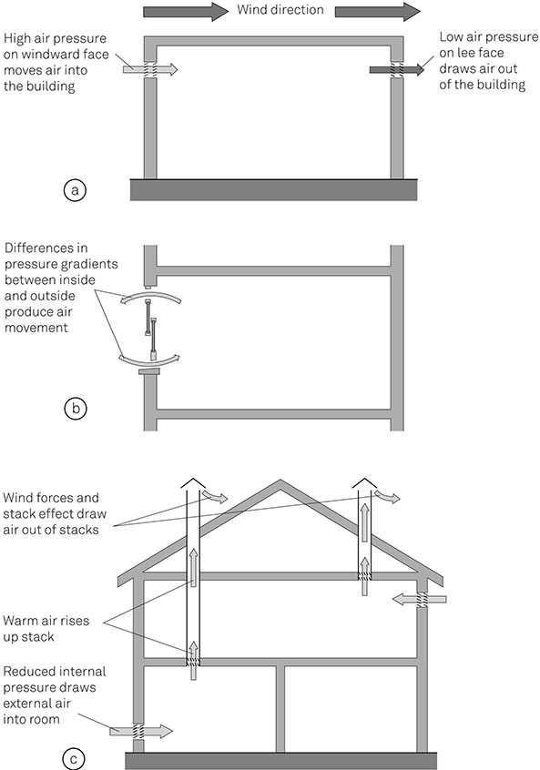
Several strategies may be used on the same building: for example, the background ventilation in a house may be provided by trickle vents built into window frames, while extraction in the bathroom is provided by a passive stack vent running from the ceiling through the roof. Natural ventilation systems for large or complex buildings will utilise wind and stack forces together to provide air movement, for example, to ventilate a building with an atrium.
The wind and stack forces acting on the building will vary over the course of a year, even where there is a prevailing wind direction. As a result, not only will the amount of air exchange vary, but a vent may act as an inlet with some wind directions but draw air out of the building with others (and even when the wind is in one direction air currents will still eddy around the vents).
The design of the ventilation system must ensure that it will work satisfactorily under all conditions. In particular, incoming air must be clean, so vents must be sited away from localised sources of pollution, such as heating system exhausts.
Cross-ventilation
Cross-ventilation (Figure 2-12) relies on differential pressure generated across the building by the wind: air enters the building on the high-pressure windward side and is drawn out on the low-pressure leeward side. The rate of air exchange depends on the wind speed and direction, and the size and location of vents. As a rule of thumb, cross-ventilation will be effective where the depth of the space does not exceed five times the floor-to-ceiling height.
Typically, cross-ventilation to provide background ventilation will be provided by trickle vents above openings or incorporated into window and door frames, which will give about 0.1–0.2 ach. Open windows on opposing sides of a building will also provide cross-ventilation, and are often used to address overheating in summer. The necessary window area is usually specified as a fraction of the floor area, with 5% of floor area appropriate for sash windows or hinged lights opening more than 30 degrees, and 10% for those opening between 15 and 30 degrees. Fully open windows can provide 6–8 ach.
The direction of the prevailing wind should be taken into account; however, even when the wind is blowing parallel to the ventilation openings pressure differences across the building will still produce some air movement. Where ventilation openings are positioned at different heights (e.g. on different storeys) there will be some drive from the stack effect, which may reinforce or counteract the wind forces. Effective cross-ventilation requires a good flow of air between different sides of the building, so will be less effective in buildings where the interior is divided by many walls or partitions.
Single-sided ventilation
Rooms and spaces with openings to only one side, or with limited opportunity for cross-ventilation, can be naturally ventilated by exploiting the air movement generated by temperature differences between the inside and outside of the building (see above: The stack effect p. 46). Air movement can take place through twin wall vents where one is near floor level and the other is close to the ceiling, or, to a more limited extent, at the top and bottom of a large open window. (A large traditional sash window with top and bottom sashes opened will give a similar effect to twin vents.)
In the summer, when the internal air is cooler, air will be drawn in at high level and drawn out at low level. In the winter, when external air is cooler, air will be drawn in at low level and drawn out at high level (see Figure 2-05). The ventilation rate achieved by single-sided ventilation depends on the temperature difference and the distance between the upper and lower openings. There will also be some air exchange driven by the wind. On some faces of a building the wind force may be the predominant driver, in which case the ventilation rate will be determined by the wind speed.
Single-sided ventilation will be effective where the room depth does not exceed twice the room height. Trickle vents can provide 0.1 ach, while fully openable windows (sized to the rules given above) will provide 4–6 ach.
Stack ventilation
Stack ventilation (also referred to as ‘passive stack ventilation’) uses the stack effect to move air up and out of a building at high level, drawing fresh air into the building at lower level (Figure 2-12c). The temperature differential between air inside the building and outside the building results in the upward drive (see above: The stack effect p. 46), and wind action across the ventilation terminal also draws air out. The stack effect has been exploited in this way for thousands of years (see box: The wind tower p. 68).
Stack ventilation can be used as part of a whole building natural ventilation system, either using shafts to ventilate buildings several floors high, or simply using multistorey spaces such as atria as the stacks. Figure 2-13 shows how a central atrium can be used to ventilate the floors to either side of it, venting air from the top and drawing air into each floor. The performance of such systems depends on stack height, temperature difference and the free area of vents. Typically, the opening at the base of the stack should be 3–4% of the floor area.
Stack ventilation is often used instead of extract fans to remove moist air from bathrooms and other wet rooms, through vertical ducts which terminate above the roof. The rate of extraction is variable, because it depends on the temperature differential, which will be less in summer, and the wind speed.
Controls
Natural ventilation relies on climate-driven forces so the ventilation rates achieved will be variable. Controlling such systems is, in most cases, a matter of opening and closing vents.
For dwellings and buildings of similar complexity, manual operation of vents and windows is generally sufficient; although where moisture control is the main function of the ventilation system, humidity controlled vents may be used. In larger buildings, controls can be integrated into the building management system, but are still limited to opening and closing vents, albeit in a sophisticated way.
Mechanical ventilation
Mechanical ventilation systems use fans to move air into, out of and around buildings. They range in complexity from simple extract systems – such as a cooker hood or shower room fan – to centralised, ducted, air-conditioning systems which incorporate filtration, heating and cooling of air and heat exchange. Mechanical ventilation systems allow substantially better control than natural ventilation systems, but they require power to operate, and need ongoing maintenance to maintain their efficiency.
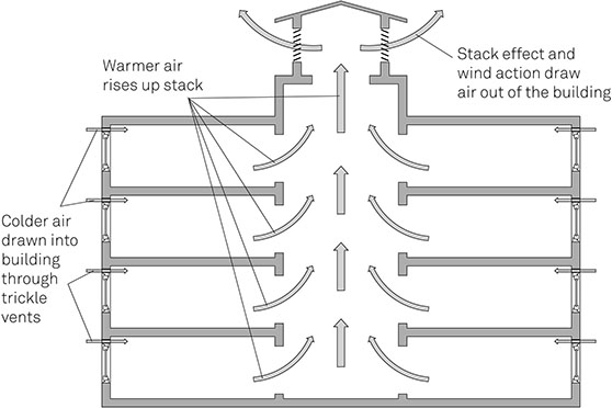
Figure 2-13
Stack Ventilation in an Atrium
The Wind Tower
The Iranian badgir, or wind tower, is a traditional ventilation system, dating back to the fourth millennium BCE, which uses wind and stack effects to cool a building’s interior.
The badgir consists of a tower, rising above the roof of the building, which is divided into a number of shafts (commonly four, but one, two and eight shafts are found) that run down into the building. Towers can be square or rectangular in plan, with the latter having the widest side perpendicular to the prevailing wind.
When the wind blows the windward shaft acts as an air inlet, while leeward shafts act as air outlets. A combination of wind forces and the stack effect results in warm internal air being replaced by cooler outside air. In a more sophisticated system (illustrated below), the incoming air is drawn along an underground water channel (qanat) which cools the incoming air by evaporation before it reaches the occupied space (see chapter 3: Vapour and heat p. 76).
The badgir is part of a broader temperature control strategy which minimises solar gain by the use of narrow streets, tall walls and small windows, and uses thermally massive fabric to make best use of the diurnal temperature swings.
The same fundamental principles can be employed in naturally ventilated buildings today.
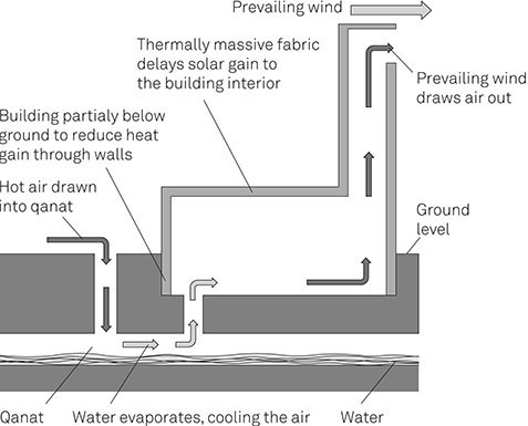
Principles of the Wind Tower
The three main types of mechanical system are illustrated in Figure 2-14 and described below.
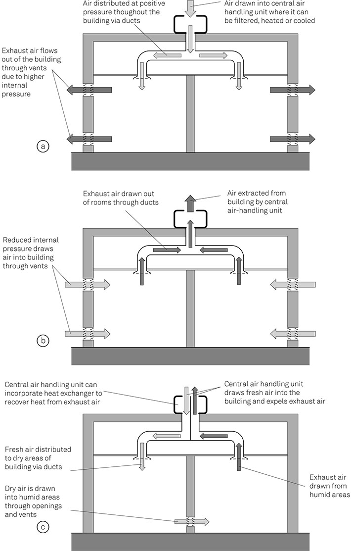
Figure 2-14
Types of Mechanical Ventilation System
Supply-only ventilation
In a supply-only ventilation system (Figure 2-14a) air is drawn into the building to a central air-handling unit and circulated by ducts to different spaces in the building. The building is maintained at a higher air pressure than outside (the systems are often described as ‘positive pressure systems’), so exhaust air is expelled through passive vents. Air can be filtered in the central air handling unit to remove contaminants before it is circulated, and it can also be heated or cooled.
Basic supply-only systems are often used in dwellings, while more complex systems which include filtration are used for operating theatres and clean rooms because the positive pressure prevents contamination from the rest of the building, and allows air to be filtered and conditioned before it is circulated.
Extract-only
In extract-only ventilation systems (Figure 2-14b) air is drawn out of the building or room either by centralised fans and ducts, or by individual fans. As the air pressure in the building is then lower than atmospheric pressure (commonly referred to as ‘negative pressure systems’) fresh air is drawn into the building through vents, louvres and other permanent openings.
Extract-only ventilation is well suited to addressing moisture levels, because such systems extract moist air at the site of generation, preventing it from travelling through the rest of the building. The extraction system can include filtration, which enables pollutants to be removed from extracted air before the air passes into the atmosphere, so preventing the further spread of pollutants.
Balanced ventilation
In balanced ventilation systems (Figure 2-14c) air is drawn into one or more central air handling units then distributed throughout the building by ducts to air outlets. Simultaneously, air is extracted from other outlets to the air-handling unit and passed out of the building. The use of separate input and output ductwork means that moist or polluted air can be extracted close to the point of contamination, which helps to prevent distribution through the building, and allows fresh air to be provided to specific locations
Balanced ventilation systems will often include a heat exchanger, to minimise the heat loss resulting from extraction and will often form part of full conditioning systems. The possibility of heat exchange makes balanced ventilation popular in dwellings with low energy use targets.
Mixed-mode ventilation
Mixed-mode ventilation is a hybrid approach which integrates natural ventilation (through openable windows and vents) with mechanical ventilation systems. Mixed-mode ventilation operates in three main ways:
- * Complementary – The mechanical ventilation runs at the same time as the natural ventilation is working. Often, the mechanical system provides the background ventilation, while building occupants can open windows if they want to. Alternatively, the mechanical system may be used to augment natural ventilation when weather conditions result in low flow rates.
- * Changeover – The ventilation provision changes between natural and mechanical according to need. The changeover may be seasonal, with windows openable in mild weather but locked shut in winter; or daily, with natural ventilation during the day and mechanical ventilation at night to provide cooling.
- * Zoned – Some spaces in the building are naturally ventilated while others are mechanically ventilated. For example, open-plan office areas may be naturally ventilated, while meeting rooms – which have higher ventilation requirements – are mechanically ventilated.
Mixed-mode ventilation can reduce energy consumption and allow smaller mechanical systems to be installed. It also improves the building occupants’ satisfaction by giving them more control over their conditions. However, it is more complex to specify and requires careful commissioning to ensure natural and mechanical systems do not work against each other.9
Design considerations
Regardless of whether natural, mechanical or mixed-mode ventilation is adopted there are several common design considerations: effectiveness, air currents, noise and heat loss.
Ventilation effectiveness
The effectiveness of a ventilation system measures how well it delivers the supply air to the building’s occupants. A system which extracted the supply air before it reached the occupants would have an effectiveness of 0 (this can happen if a supply and an extract grille are located too close together), while a system which mixed the supply air fully with the room air before it was breathed by the occupants would have an effectiveness of 1. Displacement ventilation, which introduces cold air close to floor level and extracts warmed exhaust air at ceiling level, has an effectiveness greater than 1.
Air currents
Ventilation air introduced into a building will not be at room temperature (although it will not necessarily be at the temperature of outside air). Vents and inlets should therefore be sited so as to prevent building occupants being exposed to draughts of cold air. However, even if the incoming air is well mixed, air currents can, of themselves, affect the perceived temperature: currents of air travelling at 0.1 m/s can be felt by the building occupants and will lower the perceived temperature of the air. At air speeds greater than 0.15 m/s the temperature of the air should be raised to counteract the perceived cooling. Air speeds greater than 0.3 m/s will cause discomfort and are unlikely to be acceptable, except for summer cooling.
Noise
A ventilation system which provides a direct connection for air movement between the interior and exterior of a building will also provide a route for sound transmission. Where external noise levels are high – for example because of traffic – sound transmission through vents and ducts may be disturbing to the building occupants.
For some projects the problem may be avoided by the use of acoustic vents which will attenuate the noise (see chapter 4: Controlling noise from outside p. 113), but in some locations the likely disturbance may be so great that a ventilation system which forms a direct connection between inside and outside will be unacceptable.
Ductwork can also transmit sound between rooms and zones, causing a nuisance and, in some cases, threatening privacy. The noise from the fans that are part of a mechanical ventilation system can also be transmitted through out a building via ventilation ductwork. Attenuating ductwork or silencers may be fitted to reduce noise levels.
Heat loss
The deliberate movement of air into and out of a building for ventilation purposes will result in heat transfer, which may result in a heat gain to the building (typically in the summer), or heat loss (mainly during winter).
To reduce the contribution of ventilation to heat transfer, mechanical ventilation systems can include heat exchangers, which transfer heat from warm exhaust air to the colder fresher air which is being drawn into the building. Heat exchangers are rarely compatible with natural ventilation, because they have too great an effect on the air flow.
Air in the bigger picture
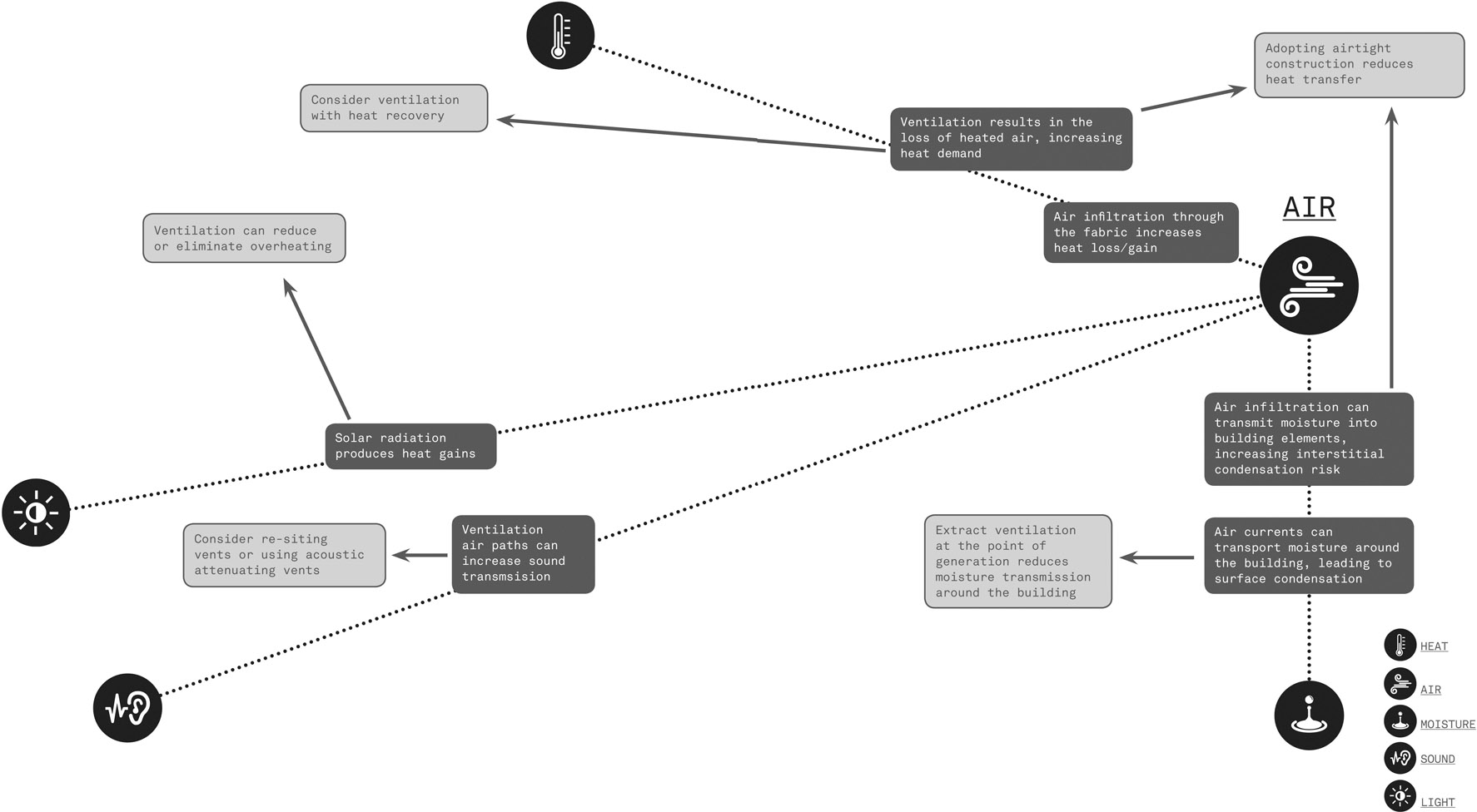
Interactions with Air