
04
Sound 
Definition:
Sound: Pressure Waves Propagated Through Fluids and Solids, That are Detected by the Organs of Hearing.
Air vibrates. It is continually set in motion by natural forces (the wind, the sea), by animals and by people. The human ear can detect those vibrations and the brain understands them as sound. Sound facilitates communication and is a medium for pleasure and joy. Yet sound can also create a nuisance and be detrimental to health and wellbeing.
When designing buildings it is not possible to eliminate noise, but by attending to the physics of sound we should be able to strike out (or at very least, reduce) the nuisance, make clear the communication and so enlarge the joy.
There are two main issues to address.
Sound from outside, or from another part of a building, travels into a space, disturbing the occupants. This intrusive sound may be caused by aircraft or traffic noise, footfalls on bare floors, televisions in adjoining dwellings, or the operation of building services. Intrusive sound can affect health and quality of life. The acoustic characteristics of the surfaces bounding a space can result in reverberation, which reduces the intelligibility of speech and makes communication more difficult. Excessive reverberation is often a problem in schools and workplaces.
With those issues in mind, this chapter will introduce the basic principles of sound and human hearing, consider the common problems caused by sound, and then outline measures that can be taken to reduce them.
Note, however, that this chapter can only address the common applications that apply to the majority of buildings; it does not attempt to deal with the special conditions required for concert halls, recording studios and the like, which require the knowledge and skills of acousticians, although, in virtually all cases, the techniques they employ are all based on the fundamental principles described here.
The fundamentals of sound
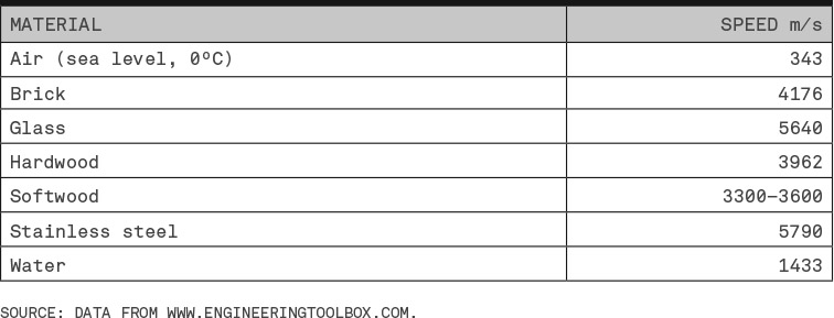
The physical phenomenon which we perceive as sound consists of waves of alternating high and low pressure travelling through air or another medium. The speed at which the pressure waves travel through a medium depends on the density of the medium (higher density reduces speed) and its stiffness (greater stiffness increases speed). Table 4.1 shows the speed of sound in common materials.
Table 4.1 Speed of Sound in Common Materials
The two main characteristics of a sound wave are:
- * Frequency – the number of cycles of high and low pressure per second. Frequency is expressed in hertz (Hz). In Figure 4-01 the solid line shows a wave pattern which has one oscillation in a second, so has a frequency of 1 Hz. The dotted line shows a wave with two oscillations in a second, so has a frequency of 2 Hz. A sound wave with one hundred cycles of high and low pressure in a second has a frequency of 100 Hz.
- * Sound pressure – the increase in air pressure produced by the wave, which is measured in pascals (Pa) and is associated with the loudness of the sound. Both waves in Figure 4-01 have the same pressure range.
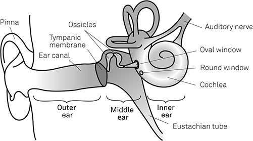
Figure 4-01 Sound Waves The human ear (Figure 4-02) is a complex physical mechanism which converts pressure waves moving through air into electrical impulses that are passed to the brain to be analysed and perceived as sound. Figure 4-02
The Human Ear The outer ear consists of the ear canal, which extends from the external flap of cartilage and skin we commonly refer to as the ear, to the ear drum or tympanic membrane. The middle ear is an airfilled cavity containing three small bones (the ossicles) that link the tympanic membrane to the cochlea, which is part of the inner ear. The cochlea is filled with fluid and lined with thousands of fine hair cells, which are connected to the auditory nerve. Pressure waves in the air travel down the ear canal and set the tympanic membrane vibrating. The vibrations are passed through the ossicles (which help to concentrate the energy of the sound waves) to the fluid in the cochlea, which sets the hair cells vibrating. The cells respond to the vibration by sending electrical impulses through the auditory nerve to the brain. Hair cells in different parts of the cochlea respond to different frequencies of vibration, giving sensitivity to pitch. Humans can typically hear frequencies of 20–20,000 Hz, although the range differs between individuals, and there is usually loss of sensitivity at the upper end of that range with age, as hair cells fail. There are two mechanisms by which sound travels into and around buildings:
Figure 4-03
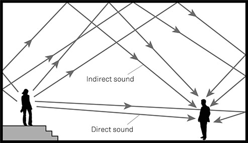
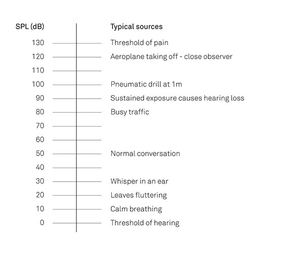
Mechanisms of Sound Transmission When sound travels through the building fabric it often takes more than one path: impact sound generated on a floor may also set up vibrations in the supporting walls; vibrations in wall cavities can travel round the ends of walls into adjoining cavities, while pipes and ducting which pass through elements also provide routes for sound transmission. Addressing this flanking transmission of sound is a crucial part of tackling sound problems. The surfaces of a space can reflect sound waves, prolonging the sound beyond its normal duration. This is shown in Figure 4-04, where the reflected sound reaches the listener slightly after the sound coming directly from the source. Figure 4-04 Reverberation and Intelligibility of Speech The human ear is sensitive to a wide range of sound pressures, from a just audible sound at 20 micropascals (20 µPa) up to the threshold of pain at about 200 Pa. The pressures at the top of the range is about ten million times greater than those at the lower end. The sound pressure level (SPL) is used to represent this range of sound pressures in a workable manner. The SPL is a ratio of the sound pressure being measured compared with the reference sound pressure of 20 µPa. Because the scale is logarithmic (that it, expressing the ratios in powers of ten) a sound which is 10 decibels (10 dB) greater than another will be twice as loud. Figure 4-05 shows the SPL for a range of common sound sources. The SPL experienced by someone hearing a sound is affected by the distance from the source. There are two reasons for this:
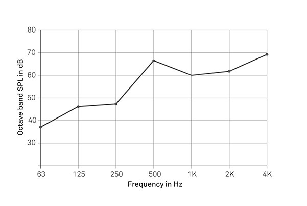
The perceived loudness of a sound is affected by its frequency, because the ear is more sensitive to sounds in the mid-frequencies – approximately 1000–4000 Hz – than to low and high frequency sounds. So, for example, a 1000 Hz sound with a SPL of 70 dB will seem as loud as a 100 Hz sound at 75 dB. To allow for that variation in sensitivity, measured sound levels are weighted to take more account of middle-range frequencies than low and high frequencies. The commonest weighting method is the A weighting curve, which reduces the contribution to loudness of frequencies below 1000 Hz. In a noise assessment a value quoted as a ‘dBA’ value, (or dB(A)) rather than just dB, has been adjusted using the A weighting curve. The acoustic performance of buildings is also different across frequency ranges. In order to give values which convey the performance across the whole frequency range, SPLs are measured in frequency bands, using either octave bands (where the frequency at the top of the band is twice that at the bottom of the band), or one-third octave bands (Figure 4-06). The results across the bands are then combined into one value, which is usually weighted to emphasise the significant frequency bands for an application: for example the Ctr correction to airborne sound transmission results is used to emphasis the effect of lower frequencies in traffic noise. Figure 4-05
Sound Pressure Levels for Common Sources of Sound Figure 4-06
A Typical Frequency Graph Showing Octave Frequency Bands The variation in the ear’s sensitivity to different frequencies means that design noise limits for spaces (e.g. maximum noise levels from building services) should also be weighted. The limits can be expressed as noise curves, which are weighted to increase the importance of higher frequency sounds. The three most commonly used curves are the Noise Rating (NR), Noise Criteria (NC) and Room Criterion (RC) curves. The airborne sound performance of an element is measured as the difference between the loudness of a sound generated on one side of an element and its loudness measured on the other side. Elements which transmit less sound produce higher differences; those which transmit more sound produce lower differences. Airborne sound tests are carried out using a standard noise source in the source room, while microphones in the receiving room measure the loudness of the noise. The sound transmission of different frequencies varies, so measurements are taken across multiple frequency bands and compared with a standard curve to obtain an average performance figure. The key measures are:
Airborne sound measurements record sound reduction, so higher values for Rw and DnTw are better. Impact sound performance is expressed as the loudness of a sound generated by a standard impact on the building structure. Elements which generate less sound have lower sound levels, while those which generate more sound have higher sound levels. Impact sound tests are carried out with a tapping machine, which strikes the floor surface with a known force, while microphones in the receiving room measure the sound level. Measurements are taken across multiple frequency bands and compared with a standard results curve to obtain an average performance figure. The key measures are:
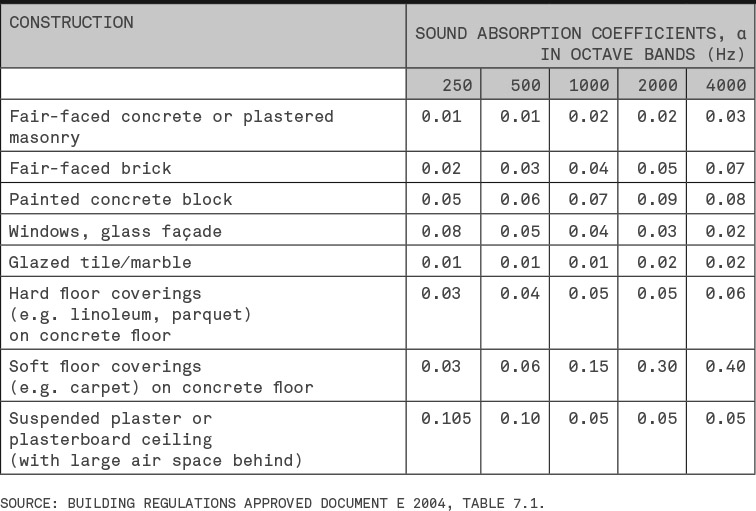
As both LnW and LnTw measure the level of sound transmission, lower values are better The change in impact sound level produced by a surface treatment is expressed as ΔLw and is measured in decibels: higher values indicate greater improvement. In situ testing of a completed building element remains the most accurate method of determining its performance; however, if the element fails to achieve the specified performance level then disruptive remedial works will usually be required. To avoid such problems it is common to rely on systems which laboratory testing shows can achieve well above the required standard. There are predictive calculations, but these are not currently widely used. Like any other calculation or modelling method, the final result depends on the standard of construction. And with sound transmission, small gaps in the fabric can be detrimental to performance. Reverberation is the length of time it takes for a sound to die away, once the source has stopped. The standard measure of reverberation time, (RT60) is the time taken for a sound to decay by 60 dB, measured in seconds. (Testing for 60 dB decay is not practicable in the field, so the first 20 dB decay is measured and the 60 dB time extrapolated. The results should be labelled as RT60(T20).) Reverberation is affected by the amount of sound absorbed by the surfaces of a space. The proportion of sound falling on a surface which is absorbed by the surface is measured by the absorption coefficient, α: A fully open window has an absorption coefficient of 1, because it will not reflect any of the sound which reaches it. Table 4.2 lists absorption coefficients for common materials. Note the coefficients vary with the frequency of the sound. Table 4.2 Absorption Coefficients for Common Surfaces The total sound absorption of a room is calculated by multiplying the area of each surface by its absorption coefficient, α. Its reverberation time depends on its volume (V) and its total sound absorption (A) and can be calculated using the formula:
The absorption coefficients for materials vary with the frequency of the sound, so the reverberation time calculations must be undertaken for several different frequency bands, typically 250, 500, 1000, 2000 and 4000 Hz.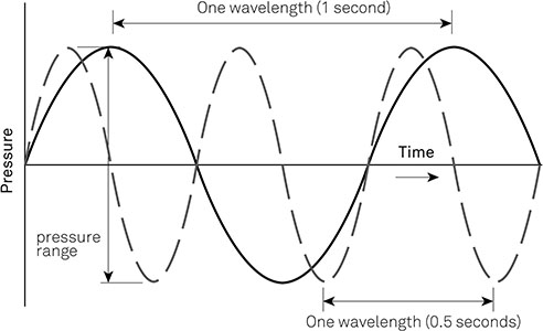
Human hearing
The mechanisms of sound transmission

Measuring sound
Loudness
Sound transmission
Reverberation and absorption
![]()
Sound, people and buildings
Sound can have a significant impact on the occupants of buildings, affecting their health, their ability to work and their quality of life.
Sound and health
Exposure to high noise levels harms the hair cells in the cochlea and damages hearing, with very short exposure to extremely loud sounds and longer exposure to loud sounds being harmful. In the UK regulations require compulsory action at 85 dB (LEPd or daily noise exposure level) and peak SPL of 137 Pa (LCpeak). Those values are, respectively, roughly equivalent to the noise from a diesel lorry travelling at 40 mph about 15 m away and a jet aircraft 50 m away.
Exposure to potentially harmful levels of sound is usually a result of specific workplace activities, such as working in factories and foundries, or with pneumatic drills or machine tools. Leisure activities, including loud music performances, can also compromise hearing.
Long-term exposure to intrusive noise, particularly in dwellings, can also cause health problems. Initially, noise can make it difficult to get to sleep or produce sleep disturbance, but persistent exposure to noise can result in sleep deprivation, loss of appetite and psychological stress.
Sound and nuisance
Often, noise reaching a space from outside the building or from an adjoining space will not be injurious to health, but will still be a nuisance. Intrusive noise can be distracting, interrupting activities and disturbing concentration. In schools and offices intrusive noise can produce noisy spaces where task concentration or learning is disrupted.
In dwellings, traffic noise, the noise of the neighbour’s television through the walls or footsteps on an upper floor, can all diminish quality of life. Problems are more likely in terraces, flats, maisonettes, hotels and halls of residence. Reverberation in circulation spaces, which typically have hard surfaces, increases the disturbance produced by traffic between occupancies.
The impact sound of rain on roofs (particularly those with metal weatherproofing) can also be intrusive.
Sound and privacy
Another aspect of acoustic privacy is the desire not to be heard: this is mainly a consideration in domestic contexts, where the fact that certain human functions are audible in other spaces in a dwelling can cause embarrassment. However, it can also be an issue in open-plan offices.
Sound and communication
Speech is a vital means of communication, so the inability to hear and understand speech is problematic. There are two main considerations:
- * Ambient noise – If ambient noise levels are too high then normal conversation and communication will not be possible. The maximum acceptable level of ambient noise for normal speech is 57 dB (LAeq) where speaker and listener are 1 m apart, but only 39 dB at a distance of 8 m. Offices will typically have ambient noise levels of 45 dB, while a light-engineering workshop will have noise levels of 45–55 dB.
- * Reverberation within the space – In some contexts, such as concert halls, long reverberation is desirable, but where speech is important (e.g. in classrooms and lecture theatres) reverberation reduces the intelligibility of speech as the reflected sound muffles the original sound.
Creating spaces which enable clear communication is important for people with a hearing impairment, because overbearing background noise and reverberation will make communication more difficult.
However, in large open-plan offices, intelligibility of speech over a distance is undesirable, as it gives problems with privacy. This can be addressed by siting ventilation outlets so that the noise from the ventilation or conditioning system forms background noise, reducing the audibility of conversations from a distance. Such a set-up will require coordination between the designer and the building services engineer.
Controlling intrusive sound
To reduce intrusive sound, the transmission of sound through the building fabric must be attenuated. That involves applying the basic principles of sound control to the building elements, as well as reducing sound transmission at perimeters and junctions with other elements.
The principles of controlling sound transmission through the fabric
There are four main physical attributes of the building fabric to consider: mass, isolation, rigidity and absorption.
Mass
A sound wave has a finite amount of energy, which is gradually used up as it travels and sets new molecules vibrating. When a sound wave travels through a dense material much of its energy will be used to set the molecules of the material in motion. If there is enough mass all the energy of the sound wave will be absorbed and converted to thermal energy. The amount of mass required to absorb a sound wave depends on the energy of the sound wave: more energy requires more mass. For instance, an impact on a dense floor will produce less sound than the same impact on a lightweight floor.
The use of dense fabric is a common method of reducing airborne and impact sound transmission, and is relatively easy when using masonry or concrete construction. In lightweight framed constructions mass can be increased by adding layers of dense plank plasterboard. As rule of thumb, doubling the mass of a building element will result in a 6 dB reduction in sound transmission. Note that the mass of the fabric is usually expressed as the mass per unit of surface area (kg/m2), rather than a density value.
Isolation
Building elements usually consist of several different layers. Sound travels less easily through elements whose layers are isolated from each other. This principle is employed in timber-framed partitions and party walls, which have two separate frames, usually lined with acoustic insulation.
In floors, an independent ceiling installed beneath a party floor will reduce transmission by isolating the wearing surface from the ceiling. Where space constraints preclude an independent ceiling, resilient bars can be fitted to the underside of the floor structure to eliminate a direct transmission path between floor and ceiling. At openings, double- or triple-glazed units contain air cavities which reduce sound transmission as well as heat loss.
Any structural connectors required to link parts of the construction (such as wall ties in masonry cavity walls) will increase sound transmission. There is also the possibility of flanking transmission if the cavity is linked to other cavities, so giving a path for airborne sound transmission.
Rigidity
Sound transmission is affected by the rigidity – or dynamic stiffness – of materials within building elements: those with low dynamic stiffness transmit less sound and can be used for noise reduction systems. A typical example is the resilient layer used in floating floor constructions, which ‘gives’ slightly on impact, reducing the transmission of impact sound from the wearing surface. Table 4.3 shows the dynamic thickness for materials commonly used as resilient layers: a dynamic stiffness of 10–50 MN/m3 is usually recommended.
Table 4.4 Recommended Reverberation Times
| MATERIAL | DYNAMIC STIFFNESS, s’ (MN/m3) |
| Mineral fibre boards (10 mm)[1] | 20 |
| Mineral fibre boards (20 mm)[1] | 10 |
| Granulated cork mats (7 mm)[1] | 150 |
| Expanded polystyrene[2] | 10-40 |
SOURCES:
Acoustic requirements must be balanced with other performance requirements, such as structural strength, in components such as wall ties, and also long-term stability in resilient layers in floating floor constructions.
Absorption
Porous materials, such as fibrous insulation or open-faced tiles, absorb sound within their air spaces as friction between the vibrating air and the fibrous material dissipates the sound energy and converts it to heat. Some of the sound energy also goes to moving the fibres.
Fibrous insulation is used widely to absorb sound, most commonly in framed constructions which do not have a great deal of mass. Absorptive materials are also used on room surfaces to absorb sound and reduce reverberation (see below: Controlling reverberation p. 114).
Controlling sound transmission in practice
Most constructions derive their acoustic performance from several attributes. This may be illustrated by considering the redevelopment of a large terrace house into multiple flats, in which a floor that was originally an internal floor becomes a separating floor between two flats. As a result, airborne transmission of sound between flats has to be addressed, as well as impact sound transmission from the upper flat to the lower flat. Because this is an existing building, which may be supposed to have a timber joist floor, relying on mass to prevent sound transmission is not an option. A more complex solution is required: one that relies upon isolation, stiffness and absorption.
The typical solution (see Figure 4-07) will involve a floating floor construction, with a resilient layer to reduce impact sound transmission by separating the wearing surface from the timber joists. The resilient layer will be formed of compressible foam, which is either installed across the whole floor, often on the original floor surface, as shown, or along the top of the existing ceiling joists. Fibrous insulation fitted between the joists will improve the acoustic absorption of the floor and dissipate much of the energy in the sound waves.

Figure 4-07
Remedial Treatment of an Existing Floor
The final part of the construction is the ceiling, which needs to be isolated from the joists, The best solution is to construct a separate ceiling which is not directly connected to the joists, but if space is constrained a resilient bar system can be used to minimise contact and sound transmission. To obtain the intended performance the floor must be designed to avoid flanking sound transmission, and services which penetrate the floor must be properly isolated.
Edges, junctions and perimeters
For any sound control solution to be effective the junctions between the treated element and other parts of the building also need to be addressed:
- * Where flanking transmission would be likely, for example in a cavity party wall, the flanking elements must be designed to reduce sound transmission. That may require denser construction and the sealing of linked cavities.
- * Air gaps at perimeters must be adequately sealed.
- * On floating floors, the wearing surface should be separated from the perimeter walls to avoid flanking transmission.
- * Service ducts and pipes can be paths for sound transmission, either through gaps where they penetrate walls and floors, or by transmitting sound directly. Services penetrations should be filled with flexible sealants and services themselves protected by acoustically insulated partitions.
The principles for controlling noise transmission into a building from outside are identical to those for controlling transmission within a building, but with three additional considerations. The vents and openings that provide fresh air for the building occupants (see chapter 2: Air for health and comfort p. 53) provide ideal paths for airborne sound transmission. Where external noise is likely to be a problem acoustic vents should be used. These are lined with acoustic foam to absorb sound, or have internal baffles which attenuate sound by setting up interference patterns. Where there is a significant noise source outside the building it may be possible to reduce transmission by siting vents and windows away from the noise source. Wherever possible, noise-generating activities on a site should be separated from noise-sensitive ones. The impact sound produced by rain on flat roofs can be treated by using thick fibrous tiles in a suspended ceiling to absorb sound. One of the most effective solutions, using a green roof (which provides isolation and absorption), will only be practicable on a limited number of projects. Noisy Neighbours Intrusive noise is hardly a new phenomenon: in the first century the satirist Juvenal complained about the noise of wagons passing along the streets at night (they were banned from Rome during daylight hours). Measures to control noise have often focused on limiting the amount of noise produced. In early modern London, the ‘Lawes of the Market’ forbade noisy disturbances at night and limited the hours of noisy trades (‘no hammar man, [such] as a Smith, a Pewterer, a Founder, and all Artificers making great sound, shall not work after the hours of nine in the night, nor afore the houre of four in the morning’). By the 18th century the possibilities of limiting noise through building design were increasingly considered: the church of St Mary le Strand in central London was built with false window openings on the ground floor to ‘keep out the Noises from the Street’. That same principle was used more recently for the Byker Wall (a 1970s housing development in the Byker district of Newcastle upon Tyne, England). The towering north face, which was expected to overlook an urban motorway, was designed with only a few, small windows, while the southern, sheltered face has larger windows, walkways and balconies.Controlling noise from outside
Vents
Layout
Impact
Controlling reverberation
The optimum reverberation time required to ensure intelligibility of speech in a room (see above: Sound and communication p. 110) depends on its function and size, with smaller rooms needing lower reverberation times than larger ones. Table 4.4 shows recommended reverberation times for a range of spaces.
Table 4.4 Recommended Reverberation Times

Where the predicted reverberation time for a room is too high, it can be reduced by selecting different wall and floor coverings and by using acoustic ceilings, wall absorbers and acoustic baffles.
The effect of the acoustic characteristics of surfaces can be seen by examining the reverberation time for an open-plan office which measures 6 m by 10 m, with a height of 3 m (volume, V: 180 m³), and with surface absorption (α) characteristics (for the 1000 Hz frequency band) as follows:
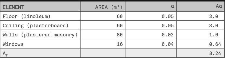
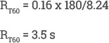
Using the formula for the reverberation time of:
The reverberation time for the room is:
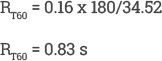
That reverberation time is excessive for an open-plan office so it must be reduced. One method would be to install absorptive panels (absorption coefficient, 0.95) to the surfaces of the smaller walls, giving revised surface characteristics as follows:
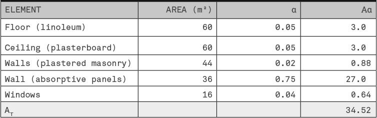
The reverberation time is now:
That figure is within the range of acceptable reverberation times for an open-plan office. If this were a live project the reverberation times would be calculated for a range of frequency bands.
Sound in the bigger picture
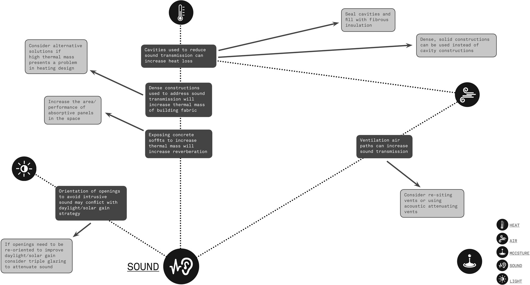
Interactions with Sound