
01
Heat 
Definition:
Heat: The Internal Energy Possessed by Atoms and Molecules; The Transfer of Such Energy from Bodies with Higher Energy to Those with Lower Energy.
Human beings need to maintain a core temperature of 37.6ºC for wellbeing (heat stroke sets in if the core temperature rises above 40.5ºC and hypothermia if it drops to 35ºC). There are physiological mechanisms that help regulate our body temperature (we sweat when we are too hot and shiver when we are too cold), as well as behavioural mechanisms (we stay out of the noonday sun). But there are also cultural adaptions: we wear clothes to keep us warm or cool; we light fires to keep us warm; and we construct buildings to provide shelter.
Until the middle of the 20th century, the main methods of regulating the internal temperatures of buildings were the use of individual heat sources (mainly open fires) and the use of air currents to introduce cooler air from outside. Now, however, heating and cooling technologies have improved, fuel is expensive and we have discovered the detrimental effects of the profligate use of energy to condition buildings in terms of pollution and climate change. The challenge for today and tomorrow is to maintain comfort conditions without an excessive use of energy (and, by extension, excessive greenhouse gas emissions).
In order to understand how to design buildings that provide a suitable internal temperature while minimising energy use, we need to understand how heat behaves in relation to the building fabric. This chapter begins by examining the fundamentals of heat, the effect of heat on materials, the mechanisms by which heat travels through them and the phenomenon of solar gain. It then considers heat transfer through the building fabric, looking at methods of measurement and the means by which heat transfer may be reduced, before considering thermal mass and how that may be measured.
The final section of the chapter addresses the energy performance of buildings, and examines how the control of heat transfer and the thermal mass of the fabric can contribute towards minimising energy consumption for heating and cooling.
Although this chapter does consider heat loss through the building fabric, we must remember that air movement can also result in significant heat transfer: this is discussed briefly in this chapter, but a more detailed treatment is given in chapter 2.
The fundamentals of heat
Let us begin by examining how materials respond to changes in temperature, and the mechanisms by which heat is transferred through the materials and air spaces that make up the building fabric. We can then consider how thermal insulation can reduce the heat transfer.
Heat and temperature
Heat is the internal energy possessed by matter: a material or object with a high level of internal energy has a higher temperature than a body with a low level of internal energy. There are two components of heat to consider:
- * Sensible heat – the heat which results in a change in temperature of a material (‘sensible’ with the meaning of being sensed or felt)
- * Latent heat – the heat involved in changing the phase of a material, without affecting its temperature (e.g. converting liquid water to water vapour requires energy, while solidifying a liquid wax will release energy)
Most of this chapter addresses sensible heat: a use of latent heat is also explored (see: Phase change materials p.35).
Temperature is the fundamental measure of heat, and is measured in kelvin, indicated by K. The scale starts at 0 K – absolute zero – with the triple point of water (the temperature and pressure at which water can be gas, liquid and solid at the same time) at 273.16 K. One kelvin is defined as 1/273.16 of the thermodynamic temperature of the triple point of water.
For day-to-day we use the Celsius scale, which has the melting point of ice (at standard pressure) at 0ºC and the boiling point of water at 100ºC. For conversion between the two scales, a kelvin is equivalent to a degree Celsius, so subtract 273.16 to convert kelvins to degrees Celsius, and add 273.16 to convert degrees Celsius to kelvin. It is worth noting that there are still a few countries (in particular, the United States) where the Fahrenheit scale is in use as part of the imperial system of weights and measures.
Determining the temperature experienced by building occupants requires the consideration of two different components of heat:
- * The radiative temperature, resulting from radiation received and emitted (see: Radiation p.6);
- * The air temperature.
Those two values are combined, by a weighting method which includes the effect of air movement, to give the operative temperature that can be used for design purposes.
Establishing a suitable design temperature can be even more difficult, because a building occupant’s perception of whether a building is too hot or too cold can be affected by the prevailing outdoor temperature as well as factors such as dress codes.1
Heat capacity and thermal mass
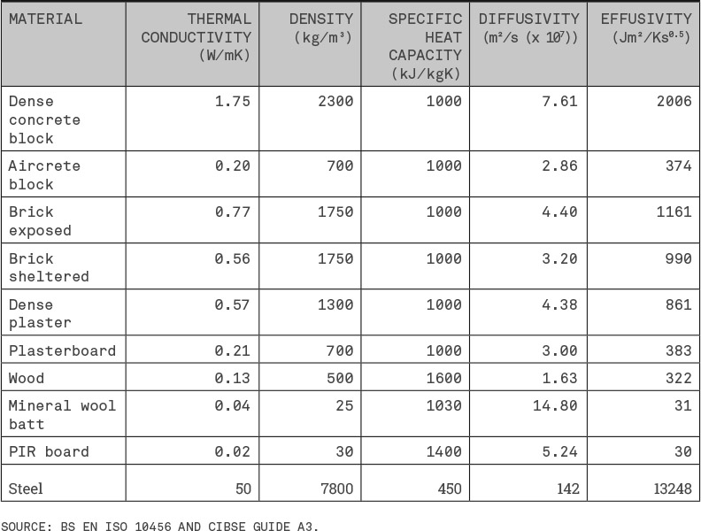
The application of heat to a material raises its temperature, and the extent of that rise depends on the material: some require a lot of energy to warm them, others require less. The amount of energy needed to raise the temperature of a material is expressed by its specific heat capacity, which is the energy needed to raise the temperature of one kilogram of the material by one kelvin (measured in J/kgK, joules per kilogram kelvin). As table 1.1 shows, many construction materials have similar specific heat capacities.
The thermal mass of a material is also affected by its density, so a more practical measure is the heat capacity, which is the energy required to raise the temperature of a layer of a certain thickness. The heat capacity of a layer is calculated by multiplying its density, specific heat capacity and thickness (in metres). Table 1.1 shows that mineral wool and dense concrete blocks have a similar specific heat capacity, but very different densities, so the heat capacity of a 100 mm layer of concrete block is nearly a hundred times that of a 100 mm layer of mineral wool.
Table 1.1 Heat Capacities of Common Materials

Heat transfer mechanisms
Where materials are hotter or colder than adjacent materials or surfaces there will be a transfer of heat from the hotter to the colder. There are three main mechanisms of heat transfer: conduction, mass transfer and radiation.
Conduction
Conduction heat transfer occurs as the molecules in solids, liquids and gases vibrate and collide against each other. Energy is passed from molecules with higher internal energy to those with lower internal energy, raising their temperature, which results in heat travelling through the material. Heat travels through different materials at different speeds: you can experience this when you touch a metal door handle and then the face of a wooden door. The metal handle feels colder, because it conducts heat away from your hand more quickly than the wood.
The rate of conduction heat transfer is affected by:
- * The proximity of molecules – in solids the molecules are packed more tightly together than those in liquids, so energy can pass more easily between them. In liquids the molecules are further apart, so fewer collisions occur. In gases the distance between molecules is even greater, resulting in less frequent collisions and even slower energy transfer.
- * The arrangement of the atoms (in solids) – for example, the atoms in metals are arranged in a tight lattice, which means the increased vibrations of the atoms produced by heating are transferred rapidly to neighbouring atoms.
- * The presence in some materials of free electrons – if some electrons within a material are not attached to atoms (typically, in metals) the electrons move when electronic or magnetic fields are applied; they move easily when their energy state is raised, so transferring energy through the material.
The rate at which heat travels through a material is expressed in its thermal conductivity, which is the amount of heat transferred per second through one metre of a material, with a one kelvin temperature difference between one side and the other. The unit of conductivity is W/mK (watts per metre kelvin). The conductivity of a material is often referred to as its lambda value, λ.
Most construction materials are composites, consisting of many elements amalgamated in different proportions. In addition to solid matter, construction materials also contain matter in gaseous and liquid state (timber, for example, typically has a moisture content between 10% and 20%). Thermal conductivities are therefore established by laboratory testing of samples.
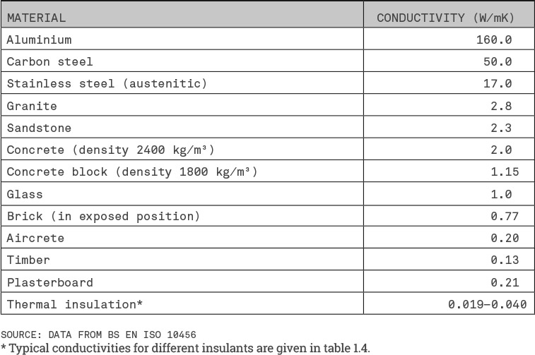
Table 1.2 sets out the conductivities of a number of common construction materials. The range of thermal conductivities is huge; metals have conductivities 425–8000 times greater than those of thermal insulants. To put those values into context: in order to achieve the same performance as 100 mm of expanded polystyrene insulation you would need 420 mm of autoclaved aerated concrete, 3.67 m of concrete and 56.7 m of stainless steel.
Table 1.2 Thermal Conductivities for Common Construction Materials
Mass transfer
Heat is transferred in gases when molecules move by ‘mass transfer’ as a result of the mechanisms of convection and advection.
Convection occurs when part of a volume of gas is heated: the molecules gain more energy and random motion increases, making the heated gas less dense. The heated gas is then displaced by cooler, denser gas, making it rise. The continued presence of a heat source will result in currents of heated gas rising and cooler gas sinking, transferring energy with the molecules. You can sense convection in gases by holding your hands above a central heating radiator. Air in contact with the radiator is warmed (mainly by conduction) and expands. It is then displaced by cooler denser air and forced upwards, as shown in Figure 1-01.
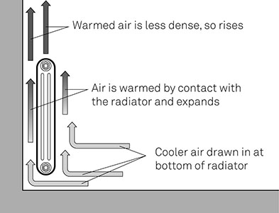
Figure 1-01
Convection Enables Heat from a Radiator to Warm the Building Interior
The rate of heat transferred by convection depends on the speed at which the gas moves (which is affected by its viscosity), the temperature difference, the direction of heat flow and the amount of energy required to raise the temperature of the gas (which is affected by its density and heat capacity).
Advection is the transfer of heat as the result of bulk movement of molecules in a gas driven by other forces, for example a difference in air pressure between the inside and outside of a building (see chapter 2 for a more detailed discussion of air movement).
Radiation
All bodies emit thermal energy in the form of electromagnetic radiation (which is discussed in more detail in chapter 5). Radiation can travel across a vacuum (e.g. radiation from the sun). A common experience of radiation is standing by a fire or stove in an otherwise cold room. The side of your body facing the fire is warmed by radiation from the fire, which is absorbed faster than you give off radiation. The other side of your body is colder because it emits more radiation to the environment than it receives.
The amount of radiation a body emits depends upon its temperature (radiation increases with temperature) and its emissivity (which expresses the radiation emission potential of the surface as a fraction of the potential of a perfect emitter – known as a black body). Emissivities lie between 0 and 1: a surface with a high emissivity will emit more radiation than one with a low emissivity. Most construction materials have high emissivities – above 0.8.
As well as emitting radiation, a body will receive radiation from other bodies, which will either be reflected or absorbed. The proportion of radiation absorbed at the surface of a body is measured by its absorptivity, which lies between 0 and 1: most common construction materials have high absorptivity and will absorb a high proportion of the radiation reaching them. A number of materials (e.g. glass) will transmit a proportion of the radiation reaching them. (This is discussed in more detail below: Controlling heat transfer through openings. p. 20)
The overall effect of radiation on the thermal energy of a body depends on the balance of radiation given out (emitted) and that received (absorbed). If all other heat flows are equal, a body which emits more radiation than it absorbs will cool, while one which absorbs more than it emits will be warmed.
Heat transfer through solids
The thermal performance of a layer of a material in a construction is expressed by its thermal resistance, which is the resistance to heat transfer of a specific thickness of a material. Thermal resistance is expressed in m²K/W (metre squared kelvin per watt): a higher thermal resistance is better for reducing the rate of heat transfer.
For solid materials, where conduction is the main mechanism of heat transfer, the thermal resistance is calculated by dividing the thickness of the material (in metres) by its thermal conductivity. The relationship between thickness and thermal resistance is straightforward: doubling the thickness of a material doubles its thermal resistance (see Figure 1-02). For the same thickness, a material with low thermal conductivity will give a higher resistance than a material with high thermal conductivity.
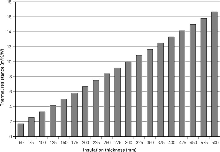
Figure 1-02 The Relationship between Thermal Resistance and Thickness
Heat transfer through air spaces
The thermal performance of air spaces within building elements is affected by all three heat transfer mechanisms.
Conduction in air spaces
In narrow air spaces conduction accounts for more heat transfer than convection, but beyond certain thicknesses (approximately 12 mm for heat transfer upward, 20 mm for horizontal heat transfer and about 360 mm for downward heat transfer) substantially more heat transfer occurs by convection.
Convection in air spaces
Temperature differences across air spaces will generate convection currents. Air in contact with the warmest face of the air space will be heated, and will expand and be forced upward by colder, denser air sinking to replace it. Because convection currents move warmed air upward (together with the energy it contains) the effect of heat transfer across an air space varies with the direction of heat transfer through the whole element:
- * Where heat transfer is predominantly upward, convection works in the same direction and will increase heat transfer. This occurs in roof cavities when heat is being transferred out of the building and also in floor cavities when heat is being transferred into the building.
- * Where heat transfer is predominantly horizontal, convection works at right angles to that transfer, and will make a small increase to the rate of heat transfer. This occurs in wall cavities.
- * Where heat transfer is downward, convection works in the opposite direction, reducing the rate of heat transfer. This occurs in floor cavities when heat is being transferred out of the building, and in roofs, when heat is being transferred into the building.
Any air currents within an air space – whether deliberately induced (see chapter 3: Ventilation for the fabric p. 96) or as a result of air infiltration – will increase heat transfer through the airspace. (A positive effect of a convection current in a wall cavity is described below: Beneficial air movement in air spaces.) If the air space is connected to outside air the thermal performance of the entire construction can be severely compromised (see: Heat loss in party walls p. 24).
Radiation in airspaces
Every surface bounding an air space in an element emits and absorbs radiation. If one surface of the air space emits more radiation than it receives there will be a net transfer of heat across the air space. Because warmer surfaces emit more radiation than cooler ones, the direction of heat transfer will generally be from the warmer side of the air space to the cooler side. The rate of radiation heat transfer across an air space depends on the temperature difference across the space, and the emissivities of its surfaces.
Determining thermal resistances of air space
There is no simple relationship between the thermal resistance of an air space and its thickness because heat transfer across an air space involves all three mechanisms of heat transfer. Figure 1-03 shows the resistances of air spaces for upward, horizontal and downward heat flows. In each case the resistance increases with thickness, but reaches a plateau when the effect of convection heat transfer exceeds that of conduction heat transfer.

Figure 1-03
Air Space Resistance by Thickness
Heat transfer at surfaces of building elements
The overall rate of heat transfer through building elements is affected by the conditions at the interior and exterior surfaces of the elements. At interior surfaces, temperature-driven convection currents account for much of the heat transfer: the rate of transfer being greatest when the direction of transfer is up, rather than down. At exterior surfaces air movement produced by the wind is more significant than temperature-driven convection; in these circumstances, the large amount of air movement occurring at the surface means that conduction heat transfer has a negligible effect.
Radiation heat transfer also occurs at interior and exterior surfaces: the rate of transfer is determined by the balance of radiation emitted and received by the surface.
The thermal performances of interior and exterior surfaces are expressed as surface resistances which combine the effects of all mechanisms of heat transfer. Commonly used values are set out in table 1.3.
Table 1.3 Default Surface Resistances (m2K/W)
| DIRECTION OF HEAT FLOW | |||
| UPWARD | HORIZONTAL | DOWNWARD | |
| Internal surface resistance | 0.10 | 0.13 | 0.17 |
| External surface resistance | 0.04 | 0.04 | 0.04 |
SOURCE: DATA FROM BS EN ISO 6946:2007.
Radiation heat loss can also result in a substantial lowering of the external temperature of roofs at night. The rate of radiation heat transfer from a roof is the balance of radiation emitted from the surface and that absorbed from the sky and clouds. On clear, still nights the rate of radiation from the roof far exceeds the incoming radiation, resulting in rapid heat loss from the roof surface (commonly referred to as ‘night time radiative cooling’), which can be beneficial in a climate where cooling is required.
On well-insulated roofs, the rate of loss is far higher than the movement of heat from the building interior, resulting in a surface temperature substantially lower than the air temperature, which is why night-time radiative cooling can result in transient condensation underneath the roof covering (see chapter 3: External climate p. 92).
Heat and light
Light from the sun, including infrared, visible and ultraviolet light, is a form of radiation; when it reaches the surface of a building it can be reflected, absorbed and transmitted. Opaque materials will reflect or absorb radiation; as a material absorbs radiation it gains energy and its temperature will rise, the extent of that warming depending on the wavelength and intensity of the light, the absorptivity of the surface and the heat capacity of the material. As the surface warms, heat will be transferred by conduction towards the building interior.
Translucent materials, such as glass, reflect and absorb radiation, but they also transmit some infrared and visible light to the building interior. The amount of solar radiation which is transmitted depends on the characteristics of the glazing (see: Heat transfer through openings p. 16). The light will fall on the interior surfaces of the building, where a large part of its energy will be absorbed by the fabric, raising its temperature. Some of the energy will be re-radiated at longer wavelengths, transmitting the heat around the interior of the building, while some will be lost to the air inside the building. The overall effect of this solar gain will be to raise the building’s internal temperature.
Thermal insulation
Thermal insulation is used to reduce heat transfer through floors, walls and roofs. There are many different types of insulation, but virtually all work by trapping small pockets of low conductivity gas within their bulk. (The exception is the vacuum panel, consisting of microporous core which is evacuated then sealed in a gas-tight cover.) The main types of insulation are:
- * Closed-cell insulants – formed with bubbles of gas in a rigid matrix that may be made of plastic in the case of extruded polystyrene (XPS), polyurethane (PU), polyisocyanurate (PIR) and phenolic insulation, or glass in the case of foamed glass insulation. Aerogel – a very light, translucent solid – also consists of gas trapped within a rigid matrix.
- * Expanded bead insulation – typically in the form of expanded polystyrene (EPS), which is available bonded as boards or as loose beads.
- * Fibrous insulation – in which pockets of still air are formed by strands of material, which may be mineral fibre, glass fibre, cellulose (usually from recycled paper) or ‘natural’ materials such as sheep’s wool.
The thermal performance of an insulant depends on how well it addresses the three mechanisms of heat transfer:
- * Conduction through the solid material – the rate of conduction depends on the type of material and its density, with lower densities reducing the amount of material through which heat can be conducted.
- * Conduction through the gas – the conductivity of the gas is key to overall performance, with air having a conductivity of 0.025 W/mK, argon 0.016 W/mK and pentane 0.014 W/mK.
- * Convection – for closed-cell insulants, convection is insignificant, because the isolation of the cells precludes convection currents. However, convection is an issue in fibrous insulants, because differential temperatures across the insulation generates convection currents. Where the direction of heat transfer is upward (in a heat-out roof or heat-in floor), convection currents will increase the rate of transfer.
- * Radiation – there is some radiative heat transfer across the air spaces within insulation, with the rate of transfer dependent on the surface characteristics of the cells or fibres. The only insulants which specifically address radiative transfer are graphite-enhanced polystyrene insulation (EPS and XPS), which have lower conductivities as a result of the graphite granules reducing radiative transfer.
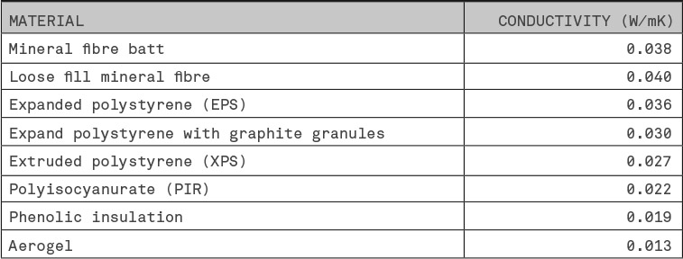
Table 1.4 gives typical thermal conductivities for common insulants.
Table 1.4 Typical Conductivities of Thermal Insulation
To ensure that the values realistically represent the performance of the fabric, the stated thermal conductivity of an insulant should account for:
- * Variations in production – The performance of insulation will inevitably vary within and between production batches. Plotting the measured conductivity from different batches will typically result in a bell curve (Figure 1-04). Using typical, or mean, values of conductivity results in half the samples having a better conductivity than that quoted, and half the samples being worse. To avoid overestimating installed performance European thermal insulation standards require thermal conductivities to be quoted as lambda 90/90 (λ90/90) values, which means 90% of samples have thermal conductivity equal to or better than the value quoted, with a 90% level of certainty.
- * Long-term change in performance – The thermal conductivity of closed-cell plastic insulation materials (such as PIR, PU and XPS) will change over time, initially as oxygen and nitrogen in the atmosphere migrate into the insulation and change the balance of gases within the cells, and later as the blowing agent migrates to atmosphere. (One reason foil facings are used on PIR boards is to reduce gas migration and improve long-term performance.) The performance of fibrous insulation will also change, for example as a result of deterioration of the chemicals which bind the fibres together. Calculations of long-term performance need to use the thermal conductivities which reflect the deterioration of performance over time: these are commonly referred to as ‘aged’ conductivities.
- * Variations with temperature – The thermal conductivity of insulation increases with temperature, mainly as a result of the higher conductivity of the blowing agent or air in the insulant. Fibrous insulants will also experience increased internal convection, further increasing the thermal conductivity. Where the in-use temperature of insulation is significantly different from the temperature at which the thermal conductivity was obtained, the conductivity or thermal resistance should be adjusted for temperature.2
- * Moisture – Water is a substantially better conductor of heat than air or other gases (thermal conductivity 0.60 W/mK, compared with 0.025 W/mK for air and 0.014 W/mK for carbon dioxide). Consequently any water absorbed by an insulant will increase its thermal conductivity (i.e. reduce its capabilities as an insulator). Where insulation is to be installed in damp conditions – for example in foundations – the potential for water absorption should be taken into account when calculating the amount/type of insulation material needed.
Figure 1-04
Determining the Quoted Thermal Conductivity of Insulation
Thermal bridging
Many constructions contain a layer of material which is regularly interrupted by a second material, for example, insulation interrupted by the timber studs, or mortar joints in aircrete blockwork: this is referred to as thermal bridging (sometimes incorrectly termed ‘cold bridging’). The interrupting material generally has a higher thermal conductivity than the main material, so the rate of heat transfer will be higher than if there were no bridging, and the U-value (see: Heat transfer through building elements p. 13) will be higher. (An exception to this is mortar bridging in stone walls, where the mortar has a lower conductivity that the stone) Figure 1-05 shows the effect on the temperatures through a wall where a layer of insulation is bridged by a structural support.
As well as affecting the rate of heat transfer, thermal bridging can also affect surface temperature, increasing the risk of surface condensation (see chapter 3: Controlling surface condensation p. 84).

Figure 1-05
Temperature Changes Caused by Thermal Bridging
Assessing heat transfer through the building fabric
We have to be able to quantify heat transfer so that we can assess the overall energy performance of buildings. The same principles apply for measuring heat transfer from the building to its surroundings (the northern European winter), or to the building from its surroundings (the Australian summer).
Heat transfer through building elements
The rate of heat transfer through a building element is dependent on the performance of the materials and air spaces and surfaces of which it is composed. In the UK and Europe the standard measure of the thermal performance of a building element is the thermal transmittance, commonly referred to as the U-value. The U-value is the rate of heat transfer through one square metre of an element’s surface, with a temperature difference of one kelvin between one side and the other. The units are W/m2K (watts per metre squared kelvin). Under identical conditions, an element with a low U-value will transmit less heat than an element with a high U-value.
The U-value of an element is the inverse of the total thermal resistance (U = 1/R).3 Figure 1-06 shows the effect of increasing the thickness of thermal insulation in a construction: the resistance increases steadily, while the U-value drops rapidly to start with (adding 50 mm of insulation to an existing 50 mm improves the U-value from 0.6 W/m2K to 0.3 W/m2K), until it reaches a point where additional insulation makes very little difference (adding 50 mm to an existing 250 mm only improves the U-value from 0.12 W/m2K to 0.10 W/m2K). When looking to improve the thermal performance of a building’s fabric it is important to compare the benefit which would be achieved by adding the same amount of insulation to different elements.
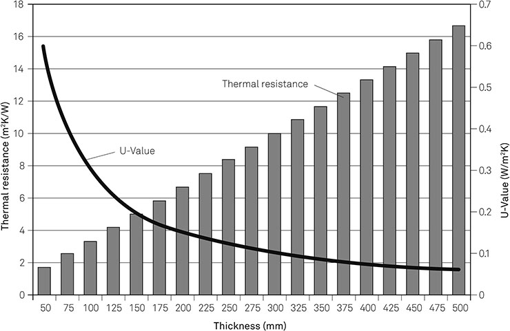
Figure 1-06
Thermal Resistance and U-Values for Increasing Thicknesses of Insulation
Direct measurement of thermal transmittances
U-values may be determined from laboratory or field measurements. Typically, laboratory measurements are carried out using ‘guarded hot box’ techniques. Essentially, part of an element, or a component such as a window, is placed inside a highly insulated box. The spaces to each side of the sample are maintained at different temperatures: one high, one low. The amount of energy needed to maintain the high temperature is measured, allowing the rate of heat loss to be measured, and the U-value to be calculated.
The U-values of existing walls can be calculated using heat flux sensors on either side of the wall. In situ measurements are particularly suitable for establishing the performance of existing walls of unknown construction.
Calculation of thermal transmittance
When an element has no thermal bridging the U-value can be calculated from the total resistance. However, most elements have thermally bridged layers so instead we use the combined method, as defined in ISO 69464 and described below (See box: The combined method p. 15).
Complex elements, such as those containing steelwork or irregularly shaped components are beyond the scope of the combined method and must be analysed by computer-based numerical modelling, which uses a two or three-dimensional computer model of an element.
The thermal analysis software imposes a network of points (nodes) throughout the model, then estimates the heat flows across the nodes to produce an initial value for heat transfer. That approximate solution is refined by an iterative process which recalculates the heat flows many times, finishing when recalculations make no significant difference to the results.
Numerical modelling takes longer than the combined method calculations, but is more accurate. It is also used to determine heat loss at junctions and to assess the effects of fixings and brackets on insulation layers.
Neither the combined method, nor numerical analysis, account for the effect of air infiltration between outside and inside through the building fabric, although the combined method can make an approximation of the effect of ventilated cavities. Heat loss through air infiltration is usually considered for the whole building (see: Whole building energy performance and chapter 2).
Heat transfer through the ground
Heat transfer through elements in contact with the ground – ground floors and basement walls and floors – is affected by the conductivity and heat capacity of the ground and the ground temperature. The temperature varies on an annual cycle, and also varies across the floor; in heat loss conditions, the ground beneath a floor will be warmer at the centre than at the perimeter (see Figure 1-07).
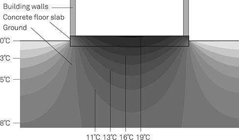
Figure 1-07
Temperature Profile below a Ground-Bearing Slab
The Combined Method
The combined method calculates U-values using (a) the resistances of the layers in the construction and (b), for each thermally bridged layer, the fractional areas that represent the proportions of each material in the layer.
The calculation proceeds by determining the thermal resistance of the construction in two ways (Rmax and Rmin), as shown in the following diagrams.
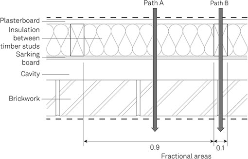
Rmax is the total resistance calculated from heat paths through the construction (referred to in standards as the ‘upper limit of thermal resistance’). The calculation involves the resistance and fractional area of each heat path, as illustrated here for a plan section through a timber-framed wall, showing two heat paths and their fractional areas.

Rmin is the total resistance calculated from the resistances of individual layers (referred to in standards as the ‘lower limit of thermal resistance’), taking account of bridging in the layer, as illustrated in this section of timber-framed wall.
In any construction containing thermally bridged layers Rmax will (as the names suggest) be bigger than Rmin: the actual total resistance lies somewhere between the two and, for the purposes of the calculation, is taken to be their average. The U-value is then the reciprocal of the total resistance.
The full combined method includes adjustments for mechanical fasteners and air leakage, as well as modifications for tapered insulation layers and inverted roofs.
Although the overall rate of heat loss through a large floor will be greater than that through a smaller floor of the same construction, the rate of heat loss per square metre will be less for the larger floor, giving a lower average U-value. A modified version of the combined method calculation takes account of these effects by considering the ratio between the floor’s perimeter and its surface area: it also allows for heat loss through the sub-floor void in suspended ground floors.
Heat transfer through openings
The thermal performance of glazing in openings (doors, windows or rooflights) and curtain wall systems depends on the performance of the glazing and the framing. The ‘glazing’ of a building may, of course, not be glass, but polycarbonate, aerogel or some hitherto undiscovered substance. For the sake of simplicity I will refer to it as glass.
The glazing is subject to conduction, convection in gas-filled cavities and radiation heat transfer in both directions. (The effect of radiation heat transfer in the form of solar gain is discussed below: Controlling heat transfer through the fabric. p. 17) Glass itself has a high thermal conductivity (1.0 W/mK, comparable with that of concrete blockwork), so most of the thermal performance in a double- or triple-glazed unit comes from the air spaces between the panes of glass. Cavity widths are limited to prevent convection.
The thermal performance of the glazing may be given as a centre pane U-value, which is the U-value measured perpendicularly through the centre of the glazing, taking no account of the effects of glazing spacers and edge seals.
Heat transfer within the frame takes place by conduction and, in hollow frames, by convection. Convection transfer in hollow frames is addressed by dividing the frame into smaller chambers which may sometimes be filled with foam insulation.
The overall U-value for an opening takes account of the performance of the glazing, spacers and frame. The U-value will vary according to the relative proportions of glazing and framing so the performance is often quoted for a standard window size and configuration.
The U-value of a window only addresses conduction heat transfer, so alternative measures, such as the Window Energy Rating (and the related Door Energy Rating), have been developed to express overall performance, taking account of conduction heat transfer, air leakage and the beneficial effects of solar gain. The Window Energy Rating is expressed in A–G bands, with A being the most energy efficient.
Heat transfer at junctions
A significant amount of heat transfer occurs at the junctions between building elements (e.g. the wall–floor junction) and at the edges of openings (e.g. the window jamb). Heat transfer through such junctions is expressed by the linear thermal transmittance or ψ-value (psi-value), which is the rate of heat transfer through one metre length of the junction, with a temperature difference of one kelvin between one side and the other. (The effect that the additional heat loss has on the temperature at the junction is calculated using the ‘temperature factor’, which is discussed below: chapter 3, Box: Temperature factor p. 88) The units are W/mK (watts per metre kelvin).
Calculating the linear thermal transmittance for a junction involves numerical modelling. For many junctions it is sufficient to model in a two-dimensional cross-section, but for complex constructions, particularly those which include steel framing, three-dimensional modelling is required.
Controlling heat transfer through the fabric
Having established how the rate of heat transfer can be determined we can now consider how to control heat transfer through the various parts of the building fabric in order to minimise the energy required to maintain comfort conditions. This section considers improvements to the thermal performance of building elements, the reduction of heat loss at junctions and the effect of air infiltration, as well as examining the performance of glazing.
The selection of thermal insulation
The use of thermal insulation is essential for reducing heat transfer through the elements that separate the conditioned interior of a building from outside. When selecting an insulant for a particular application there are six main criteria to consider:
- * Thermal performance
- * Thickness
- * Moisture
- * Strength
- * Air movement
- * Installation
Other considerations – beyond the scope of this book – might include embodied carbon, a requirement for local sourcing and price. Suffice to say that the better an insulant performs in the aspects listed above, the more it will cost.
Thickness
Any insulant could provide a specified U-value, but the required thickness would vary with its thermal conductivity. In some constructions – such as a cold pitched roof – there are no constraints on thickness, which means that an insulant with a higher thermal conductivity (say, 0.040 W/mK) may be used. In other constructions – notably walls – space constraints require the use of insulation with a lower conductivity (say, 0.022 W/mK) to provide the required thermal performance.
Moisture
The presence of water in an insulant will affect its thermal performance. The extent of deterioration depends on:
- * The extent of exposure to moisture
- * The rate at which the material takes up water
- * The effect of moisture on the thermal performance
Closed-cell insulants are the least susceptible to moisture, because their structure makes it difficult for water to travel through the material by capillary action (see chapter 3: Capillary action p. 78). Fibrous insulants have an open structure and are more susceptible to moisture, although moisture-repellent treatments applied during manufacture will reduce water transmission. Nonetheless, 1% water content (by volume) can more than double the thermal conductivity of fibrous insulation.
Where long-term exposure to moisture is expected (e.g. below ground or on inverted roofs), a closed-cell insulant will be required.
Strength
The physical performance of insulation under a load is expressed as its compressive strength, which is the pressure required to compress the material by 10% or to break it. However, long-term performance is measured by constant compressive stress, typically to give 2% deformation over 50 years. Constant compressive stress values will be several times smaller than the compressive strength.
In many applications there is very little loading on insulation, but floor insulation will be subject to the dead loads of the floor construction and the live loads resulting from the occupation of the building. Floor loads in domestic and low-rise commercial projects can usually be met by mineral fibre and closed-cell insulants, but specialist applications, such as cold storage areas, require very high compressive strengths, with XPS being the only realistic option.
Air movement
The structure of fibrous insulation allows the air within it to circulate as a result of convection currents driven by the warming of air at the bottom of the insulation, increasing the rate of heat transfer through it. Air currents across the surface of fibrous insulation will draw out warmed air, replacing it with colder air.
Installation
For insulation to achieve anything close to the design performance it must be installed properly, forming a layer without gaps, fitted tightly against adjoining parts of the construction. Where insulation is to be fitted in a continuous layer (e.g. over a floor or flat roof, or across the face of a wall) rigid boards and batts are suitable. The use of interlocking boards with tongued and grooved or ship-lapped edges will avoid gaps and reduce air infiltration at board junctions.
Where insulation is to be fitted between structural members it is easier to get a tight fit with flexible material, such as mineral fibre, rather that trying to cut rigid boards to size. This is especially true for refurbishment projects where insulation is to be fitted around irregularly shaped and spaced timbers.
Reducing the effect of thermal bridging
The effect of thermal bridging on an element’s thermal performance depends on:
- * The relative conductivities of the two materials in the bridged layer – where the conductivities are close (e.g. mortar (0.94 W/mK) and brick (0.77 W/mK)) bridging will have a negligible effect, but the effect will be substantial where insulation layers (typically 0.022–0.040 W/mK) are bridged by timber (0.13 W/mK) or steel (15 W/mK);
- * The relative proportions of the two materials – Figure 1-08 shows how the U-value of a timber-framed wall changes if the proportion of timber bridging the insulation layer is increased (note that 15% bridging is the default percentage for such calculations).
Ideally, thermal bridging should be avoided, but there are many constructions, such as those with timber and steel framing, in which space constraints make it inevitable. In such cases the effects of thermal bridging may be mitigated by:
- * Increasing the thickness of the bridged insulation layers
- * Reducing the proportion of bridging, (e.g. large-format aircrete blocks with thin adhesive joints give 1.3% bridging compared with 6.7% for standard-format blocks laid in mortar)
- * Replacing some insulation between framing with a continuous layer of insulation over the face of the framing
- * Using proprietary components to form thermal breaks and reduce heat transfer: this is particularly important where steel brackets and fasteners penetrate insulation layers
Figure 1-08
The Effect of Bridging Percentage on Thermal Performance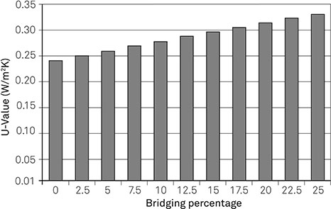
Improving the thermal performance of air spaces
The rate of radiation heat transfer across an air space depends in part on the emissivity of its surfaces, so it is possible to reduce the rate of transfer by forming one or more of the surfaces of the air space from materials with low surface emissivities (typically 0.03–0.05) such as:
- * Reflective metal facings of PIR insulation boards
- * Membranes with metalised surfaces
- * Encapsulated aluminium foil membranes
- * Multi-foil membranes
Table 1.5 shows the increase in thermal resistance of a 25-mm wide cavity when one or both surfaces have low emissivity. As with any cavity, the direction of heat transfer affects the thermal resistance. When assessing the long-term performance it is important to use an emissivity value which takes account of the effects of dust and contamination of the surface and the consequent reduction in thermal resistance. Note also that low-emissivity surfaces are also reflective: in some situations an anti-glare coating is required to reduce the risk to installers (and the coating will also increase the emissivity).
Although low-emissivity surfaces do improve the thermal resistance of an air space, in virtually all cases thermal insulation to the same thickness would provide an even higher resistance. It is therefore sensible to use low-emissivity surfaces only where there are designed air spaces in the construction, rather than deliberately introducing an air space.
Table 1.5 Cavity Resistances for Different Surface Emissivities (m2K/W)
| DIRECTION OF HEAT TRANSFER | SURFACE CHARACTERISTICS | ||
| TWO STANDARD SURFACES | ONE LOW-EMISSIVITY; ONE STANDARD SURFACE | TWO LOW-EMISSIVITY SURFACES | |
| Vertical, heat-up | 0.163 | 0.454 | 0.481 |
| Vertical, heat-down | 0.193 | 0.798 | 0.884 |
| Horizontal | 0.184 | 0.665 | 0.724 |
Note: These figures are calculated to BS EN ISO 6946:2007 for a 25 mm deep unvented airspace, with a mean temperature of 10°C. Standard surface: emissivity = 0.9; low-emissivity surface: emissivity = 0.05.
Controlling heat transfer through openings
When we consider heat transfer through openings we must first address heat transfer which occurs by a combination of conduction, convection and radiation, and then consider the transfer of solar radiation and light.
Heat loss
The rate of heat transfer through openings is typically six to eight times greater than that of the elements in which they sit. This is hardly surprising, given that the thermal conductivity of glass is similar to that of concrete and it is installed in thin layers.
Heat transfer can be reduced by using double or triple glazing in which two or three panes of glass are separated by narrow air spaces. (Although wider cavities would reduce conduction heat transfer, they would simultaneously increase convection heat transfer.) Further reductions in heat transfer may be made by filling the cavity with a gas that has a lower conductivity than air, such as argon and krypton.
The effect of glass on radiation heat transfer depends on the wavelength of the radiation (see chapter 5: Light and materials p. 21). Visible light and infrared light are transmitted, but radiation with longer wavelengths, such as that emitted by the internal surfaces of the building, is largely absorbed by the glass.
Applying a low-emissivity coating on one of the internal surfaces of double or triple glazing can reduce the amount of radiation transmitted across the cavity (in the same way as a lowemissivity surface does in a wall cavity).
There are two main types of low-emissivity coating:
- * Soft coat – multiple thin layers of silver applied after manufacture of the glass. Soft coatings give emittances of 0.05–0.10, so are more effective than hard coatings, but they are susceptible to moisture and physical damage.
- * Hard coat – modified tin oxide coatings applied as part of the manufacturing procedure. Hard coatings give emittances of 0.10–0.20. They are more resistant to damage than soft coat, but are also more expensive.
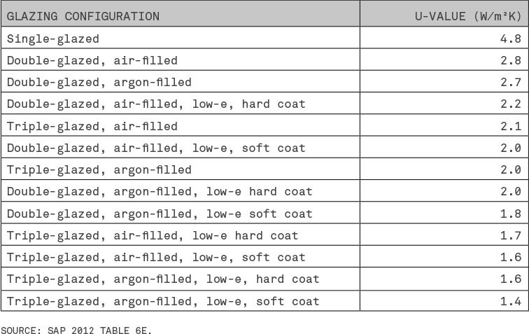
The thermal performance of existing windows can be improved by the application of lowemissivity window films. Table 1.6 summarises the typical range of U-values which can be obtained with different glazing configurations.
Table 1.6 Typical Thermal Performance of Windows (Wood Frame, All Units With 12 Mm Gap)
Of course, other components contribute to the overall thermal performance, including the spacers of double- or triple-glazed units and the framing members. Metal frames present a particular challenge, given the high thermal conductivity of steel and aluminium: the frames should be formed with thermal breaks, typically of neoprene rubber, to isolate the interior components from the exterior components and so reduce conduction heat transfer.
Solar transmission
When radiation from the sun reaches the glazing of an opening some radiation will be reflected back from the glass, some will be absorbed and re-radiated at a longer wavelength, and some will be transmitted to the building, where it will provide illumination and warm the interior.
The fraction of solar radiation which passes through glazing is expressed by the g-value, which is a value between 0 and 1. In some countries the solar heat gain coefficient (SHGC) is used. This is effectively a g-value for the whole window, taking account of the glazing, framing and screens.
The g-value may be quoted for the glazing of an opening or for the whole component (this is sometimes indicated with a ‘window’ subscript: gwindow). Typically, standard double glazing will have a g-value in the range 0.60–0.75, while triple glazing will have lower g-values.
The proportion of visible light passing through a window can be expressed as the light transmittance. The light transmittance value for a window will be similar but not identical to its g-value, because glazing responds differently to visible and infrared wavelengths.
Where solar gain will be beneficial to reduce energy use, glazing with high g-values is preferable. However, where solar gain is likely to lead to overheating, solar control glazing should be used to limit heat gain. This may involve tinted glass or reflective coatings, which will also reduce the transmission of visible light.
A better solution is to use glass with spectrally selective coatings, which will transmit a high proportion of solar radiation at visible wavelengths, but a much smaller proportion of infrared radiation, so maintaining the benefit of daylight, but reducing heat gain. Low-emissivity (low-e) coatings intended to reduce heat transfer will also reduce the amount of solar radiation passing through the glazing and so limit solar gain.
Reducing heat transfer at junctions
The reduction in elemental U-values over recent decades has resulted in heat-transfer at junctions forming a much greater proportion of overall heat transfer. For example, in a dwelling built to meet the regulatory standards of 1995, junction heat loss would account for roughly onefifth of fabric losses, but junction heat loss would account for two-fifths of losses in the same dwelling built to meet 2013 standards. Consequently, any serious attempt to reduce heat transfer must attend to junctions.
There are two main constraints which affect junction heat loss:
- * The geometry of some junctions results in a greater exposed heat loss surface on the exterior than on the interior (Figure 1-09), resulting in additional heat loss. For such junctions it is therefore not possible to eliminate the additional heat loss, only reduce it.
- * Structural requirements often prevent the formation of a continuous layer of insulation across the junctions. For example, Figure 1-10 shows a conventional wall junction, where the loadbearing structure of the wall prevents the insulation in the ceiling from connecting with the insulation in the wall.
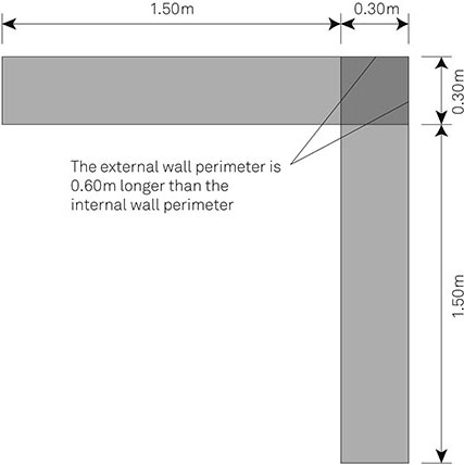
Figure 1-09
Plan Section of a Wall Junction Showing the Greater External Surface Area

Figure 1-10
Cross-Section of the Wall-Ceiling Junction at a Gable
Within those constraints, it is possible to minimise the heat loss at junctions by following four rules of thumb:
- * Minimise the number of junctions – the use of several different construction types to form the thermal envelope will produce more junctions, more discontinuities and more heat loss.
- * Set door and window frames to overlap the insulation plane, preferably rebating them into the full thickness of the insulation.
- * Specify lintels carefully. Steel lintels transfer heat rapidly through walls because of their high thermal conductivity. Use well-insulated lintels and consider using two separate lintels where the wall contains a cavity.
- * Overlap insulating layers to reduce bridging paths. This is particularly useful to address wall/floor junctions and wall/roof gable junctions (see Figure 1-10) where the structural constraints prevent continuity of insulation.
Good thermal detailing will also produce a more airtight structure and so contribute to reducing heat transfer by air leakage (see chapter 2: Infiltration p. 48).
Air infiltration
Air movement by ventilation and by infiltration will also move heat into and out of the building. As will be seen in chapter 2 it is important to maintain good internal air quality: the best strategy is to eliminate unintended air movement and deliberately supply the necessary clean air, adopting a strategy of ‘build tight, ventilate right’.
Heat Loss in Party Walls
In the UK a common method of preventing sound transmission between semi-detached or terraced houses is to construct the party wall from two leaves of masonry or timber framing with a cavity between them (see chapter 4: Isolation p. 111). The cavity in the party wall usually extends for the full height of the dwelling, terminating at the underside of the roof. In many houses, the party wall cavity is continuous with the external wall cavity, in order to reduce sound transmission around the edges of the party wall.
Until recently, building regulations in the UK presumed that there was no substantial heat loss through party walls because the dwellings on either side were likely to be heated to a similar temperature. However, research carried out by Leeds Metropolitan University (2007) showed that cavity party walls produced substantial heat loss. The result should not have been unexpected, because it only confirms the normal movement of air in a cavity.
Heat travels by conduction through each leaf of the party wall from the dwelling into the cavity, where it warms the air in the cavity (as illustrated below). The warmed air rises up the cavity, passing out to the atmosphere at the roof junction, and is replaced by cold air drawn in from the connected cavities in the external walls. The overall result is a continuous flow of cold air into the cavity, producing high levels of heat loss.
The solutions are to avoid wall cavities altogether (and rely on other mechanisms to reduce sound transmission) or to fill the cavity with fibrous insulation and seal around its perimeter. Holistic thinking about all parts of the wall’s performance is crucial.

Heat Loss in Cavity Party Walls
Assessing thermal mass
Having examined how to limit heat transfer through the building fabric, we can now consider how the capacity of the building fabric to absorb energy – its thermal mass – affects the building’s response to changes of temperature. Thermal mass can be determined using the ‘steady state method’, which simply calculated the amount of energy needed to raise the temperature of a construction, or by using the ‘dynamic method’, which assesses the response of the fabric to changing conditions over time.
Steady state method
The κ-value (kappa-value) is the amount of energy required to raise the temperature of a square metre of the building element by one kelvin, and is expressed in kJ/m2K (kilojoules per metre squared kelvin). It is the sum of the heat capacities of the layers of which the element is composed, excluding material which lies:
- * More than 100 mm from the internal surface (Figure 1-11a) – for example, in an external wall the κ-value would include the thermal mass of the internal finish and some of the masonry. This limit is imposed because only those parts of the element closest to the surface are involved in daily temperature variations.
- * More than midway through the element (Figure 1-11b) – for example, only the first 40 mm of an 80 mm thick partition wall would be included in the calculation. This prevents the overestimation of the thermal mass of the internal elements when both surfaces are assessed individually.
- * Beyond thermal insulation (Figure 1-11c) – for example, if a wall has internal insulation behind a plasterboard lining, the κ-value would include only the plasterboard.
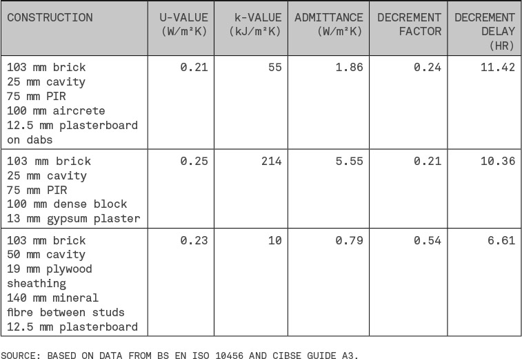
Table 1.7 shows the κ-values of common constructions. Masonry and concrete constructions have much higher κ-values than timber-framed constructions, except where internal insulation isolates the thermal mass of that masonry.
κ-values are generally used in month-based steady state analysis of energy demand, such as the UK’s national calculation methodologies, SAP and SBEM.
Table 1.7 Typical K-values
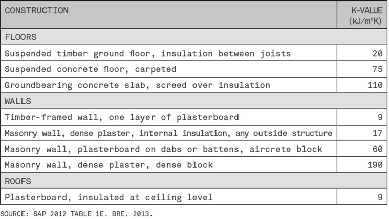
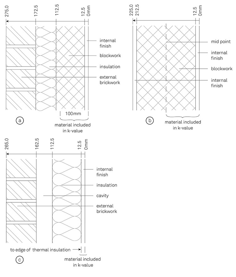
Figure 1-11 Limits on Measurement for Calculating Kappa Values
Dynamic method
The dynamic approach to thermal mass, commonly referred to as the ‘admittance method’, uses the density, specific heat capacity and thermal conductivities of materials to calculate measures of thermal mass, which can then be used to assess the thermal performance of elements on an hourly basis.
The dynamic performance of materials can be expressed by:
- * Thermal diffusivity – a measure of how rapidly heat travels in a material. Under daily temperature cycles, heat will travel further into materials with higher diffusivity, which means they will be more effective for cyclical storage of heat.
- * Thermal effusivity – the ‘thermal inertia’ of a material, that is its capacity to absorb and release heat. A material with a high effusivity will be able to store and release a large amount of heat.
Table 1.8 shows that brick and dense concrete have higher diffusivities and effusivities than aircrete, while the thermal insulants have diffusivities in the same range as masonry, but have effusivities which are substantially lower. Brick and concrete will therefore be able to store much more energy than thermal insulants.
Table 1.8 Dynamic Thermal Performance of Common Construction Materials
The dynamic performance of elements is assessed by analysing a notional 24-hour heating and cooling cycle to determine the key properties of admittance, decrement and surface factor.
Admittance
Admittance, Y, (W/m2K, watts per metre squared kelvin) is a measure of how rapidly heat will pass between the surface of an element and the interior of the building. Admittance is most strongly affected by the part of the element nearest the surface. Figure 1-12 shows the U-values and admittances for different thicknesses of three typical materials: one dense (concrete); one medium weight (blockwork); and one lightweight (insulation). The calculations are based on the values in table 1.9. Although the dense and medium weight materials have much higher admittances than the lightweight material, in each case the admittance is practically constant beyond a certain thickness. This stability justifies the use of the 100-mm thickness limit in the steady state κ-value calculations.
Table 1.9 Properties of Materials in Figure 1-12
| DENSITY (kg/m3) | CONDUCTIVITY (W/mK) | SPECIFIC HEAT CAPACITY (J/kg m3) | |
|
|
|||
| Concrete | 2500 | 1.5 | 1000 |
| Blockwork | 1000 | 0.25 | 1000 |
| Insulation | 25 | 0.03 | 1000 |
SOURCE: BASED ON DATA FROM BS EN ISO 10456 AND CIBSE GUIDE A3.
Table 1.10 shows admittance values for typical constructions. Those with higher admittances will absorb more heat from the occupied space than those with lower admittances, and so will be better for reducing cooling loads (see: Solar gain p. 31).
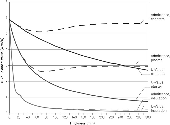
Figure 1-12
U-Values and Admittances for Three Common Materials
Table 1.10 Typical Dynamic Thermal Mass Properties For Walls
Decrement and decrement delay
The outside surface temperature of an element will vary over the course of a day as a result of changing air temperature and radiative losses and gains. Some of the heat at the surface will travel through the element and produce temperature variations at the internal surface. However, the temperature range at the internal surface will be smaller than that at the external surface, because the thermal mass of the structure acts as a damper on the heat flow. This is illustrated in Figure 1-13.
The effect of thermal mass on the temperature change is measured by the decrement factor, f, which is the ratio of the internal temperature range (minimum to maximum) to the external temperature range. For example, a wall which experiences a 20ºC temperature swing on the outer face, but only a resulting 5ºC swing on the inner face, would have a decrement factor of 0.25. The time taken for heat to pass from one side of the structure to the other is the decrement delay, which is measured in hours. Examples of decrement factor and decrement delay for typical constructions are shown in table 1.10 above.
The decrement factor and decrement delay are used to assess the impact of external temperature on the building. Where the diurnal temperature range is substantial, constructions with low decrement factors are desirable: the thermal mass of the structure will moderate temperature extremes, minimising internal gains and losses.
A decrement delay of nine or ten hours will ensure that the effect of high external temperatures (which occur at the middle of the day) will not reach the building interior until the cooler night, at a time when the rise can be mitigated by ventilation cooling (see chapter 2: Ventilation p. 60).
Surface factor and surface delay
The surface factor, F, compares the cyclical variation in heat flow from a surface to the cyclical variation into the surface. (It is ridiculous that the decrement factor is f and the surface factor is F. Sometimes building physics seems designed to be confusing!) The surface factor is used to assess the effect of solar radiation and internal gains on internal surfaces. Structures with high admittances will have low surface factors. The time lag between the peak flows is defined by the time factor, ψ (psi).
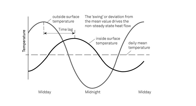
Figure 1-13
Daily Variation in Temperature through a Wall
Mass-enhanced U-values
U-values are usually calculated independently of thermal mass, but if it is likely that the exterior temperature will fluctuate above and below the internal temperature of a building over the course of a day, a more accurate picture of performance can be gained by taking thermal mass into consideration (rather than using the basic steady state U-value calculation).
As the balance of internal and external temperature changes, so the direction of heat flow through the element will change. At night, when the external temperature is lower, heat transfer will be from inside to outside, but the transfer will be slowed down by the thermal mass of the structure. During the day, if the internal temperature is lower than outside, the direction of heat transfer will reverse, and some of the heat stored within the construction will travel back to the building interior. Taken together, those effects will give a lower effective U-value.
The improvement in performance produced by a mass-enhanced U-valve is directly related to the decrement delay: where there is a wide diurnal temperature variation, a structure with higher thermal mass will transfer less heat and so be more energy efficient.
Whole building energy performance
Having considered the main interactions of heat with the building fabric we can now examine how they can be applied in order to design buildings which provide suitable internal conditions with minimum energy use. We will begin by considering how to control solar gain, then examine how to minimise heating demand, and finally look at how to avoid overheating while minimising cooling demand.
Solar gain
In temperate climates solar gain is generally beneficial during the heating season because it can supply part of the heating demand. However, it can be problematic in other seasons – potentially raising internal temperatures to uncomfortable levels. In other climate zones solar gain may be problematic in all seasons. But irrespective of whether solar gain is beneficial or problematic, there are three fundamental considerations:
- * The amount of solar radiation at the site, which is determined by the building’s location
- * The amount of that radiation reaching the openings, which is determined by the orientation of the building and the shading of the openings
- * The amount of solar radiation which passes through the openings to the interior, which is determined by the characteristics of the glazing (see above: Controlling heat transfer through openings p. 20)
In some projects it will also be necessary to control indirect solar gain through the opaque fabric.
Location
The primary determinant of the amount of solar radiation a building can receive during a year is its latitude (see chapter 5: The sun).
The amount of solar radiation received on the facets of a building will vary with their orientation. Figure 1-14 shows the relative amount of solar energy falling on vertical surfaces at different compass directions for a site at 55ºN (e.g. northern England/southern Scotland). The heating season values in this example show a large bias towards SE-S-SW compared with NW-N-NE, when the sun is low on the horizon. The differences are not as great during the summer when the sun has the greatest arc. Solar radiation will also be more intense during the summer, because the sun is higher in the sky.
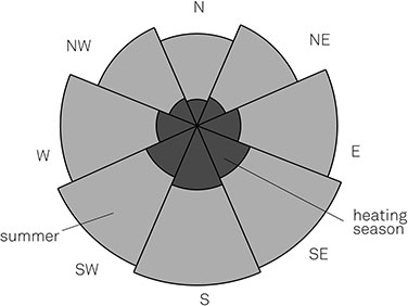
Figure 1-14
Relative Proportion of Solar Energy by Compass Direction
Data derived from SAP 2012
Seasonal differences are more marked at more northerly/southerly latitudes: at the equator the sun is directly overhead at noon, with little variation in its path or day length through the year. The amount of available solar radiation will also be affected by the climate, as cloud cover will reduce the amount of radiation reaching the ground.
Orientation and shading
The proportion of the available solar radiation a building receives will be affected by the orientation of openings and their shading. For a building with the solar potential shown in Figure 1-14 the maximum benefit of solar gain in winter would be obtained by setting a high proportion of the area of openings to face between south-east and south-west. However, adopting that orientation pattern might not be beneficial over the whole year, because the reduction in heating energy demand produced by solar gain in the winter might be outweighed by cooling energy demand during the summer.
The change in the angle at which solar radiation reaches the earth (see chapter 5, Figure 5-03 p. 122) can be used to maximise the benefit of solar gain in winter, while minimising gain in the summer. For example, as Figure 1-15 shows, in the winter (when the sun is at its lowest), solar radiation will penetrate deep into a building, while in the summer, (when the sun is higher), direct solar radiation can be blocked by shading the opening with an overhang (such as a deep soffit on a pitched roof) or brise soleil. External blinds will also reduce solar gain, but internal blinds and curtains will be less effective, because the solar radiation will already have reached the interior of the building.
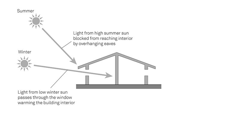
Figure 1-15
Shading an Opening with an Overhang to Control Solar Gain to the Interior
Reducing heating demand
Figure 1-16 is a simplified schematic diagram showing the relationship between the main factors which go towards ensuring the building is maintained at the design temperature. (One simplification is the omission of energy for artificial lighting, which is affected by the sizing of the windows, but is, in turn, linked to the rate of heat loss through the openings and the amount of solar gain.) Reducing the heat losses on the left-hand side of the diagram, by minimising heat transfer through the fabric and through air movement, will reduce heating demand. However, on the right-hand side of the diagram, maximising the beneficial effect of solar gain will reduce the heat demand.

Figure 1-16
Factors Affecting Heat Demand
The building needs adequate controls to ensure that the heating system responds promptly to the changing temperature inside the building. The complexity of the heating system and its controls will, necessarily, vary with size and complexity of the building and the size of the acceptable temperature range. (However, the design and specification of heating systems and their controls is beyond the scope of this book.)
Finally, to optimise energy demand it is crucial to consider the role of thermal mass.
Thermal mass and heating
When a building is heated, a part of the energy will raise the temperature of the fabric, rather than the building’s interior air spaces, and fabric with high thermal mass will absorb more energy than fabric with low thermal mass. A building with high thermal mass will therefore take longer to reach the desired temperature. Similarly, when the heating is turned off the building with high thermal mass will cool more slowly, as heat will be released from the fabric into the building interior.
Specifying fabric with high thermal mass helps to maintain a steady internal temperature because it dampens slight variations: if the temperature starts to drop, the structure will release some of the stored energy back into the building’s interior. Conversely, if the temperature starts to rise further the structure will absorb some of the energy. (A useful analogy for this aspect of thermal mass is the momentum of vehicles: a heavy lorry will require more energy and a longer time to reach 80 km/h than a car, but is easier to keep at a steady speed.) Fabric with high thermal mass is therefore suited to buildings which are continuously occupied and maintained at a similar temperature throughout the heating season (e.g. hospitals).
The effect of thermal mass on heating demand in intermittently heated buildings depends on the heating pattern and the fabric heat loss. In moderately well-insulated dwellings (which could be characterised by a wall U-value of 0.25 W/m2K) which are heated twice a day, low thermal mass minimises the amount of energy required to bring the building up to temperature in the morning and evening, although it also means the buildings will cool rapidly once the heating is turned off. This represents a typical domestic heating pattern for the UK: a few hours around breakfast and a longer period in the evening.
However, if the dwelling is very well insulated (characterised by a wall U-value of 0.15 W/m2K) the amount of heat lost (and therefore the temperature drop) between heating periods will be much less, and high thermal mass will be help to minimise the temperature drop and require less energy over the daily heating cycle.
Reducing cooling demand
Figure 1-17 is a simplified schematic diagram showing the relationship between the main factors associated with overheating. On the left-hand side the climatic conditions result in heat transfer into the interior through air movement and through the fabric, while solar radiation results in heat gains through openings and through the fabric.

Figure 1-17
Factors Affecting Cooling Demand
The risk of overheating can be mitigated, and the need for mechanical cooling reduced or even eliminated by:
- * Minimising solar gain through the opaque fabric and openings
- * Reducing heat transfer through the fabric from outside to inside6
- * Using ventilation systems to remove warmed air from the building and introduce cooler air (see chapter 2: Air for moderating temperature)
- * Making use of the thermal mass of the fabric
The rest of this section considers the measures available to minimise solar gain, and how thermal mass may be employed to reducing overheating.
Overheating through opaque fabric
A proportion of the solar radiation falling on the opaque external surfaces of a building will be absorbed by that surface, raising its temperature (see above: Heat and light p. 9). Over time, the heat generated at the surface will travel into the building, eventually reaching its interior and warming it by radiation and convection. The potential for overheating can be addressed, firstly by reducing the amount of radiation absorbed at the surface and secondly by slowing the rate of heat transfer from the external surface to the building interior.
The proportion of incident solar radiation which is absorbed is determined by the reflectance of the surface, because surfaces with high reflectance will also have low absorptivity, given that, when there is no transmission of radiation, the total of reflectance and absorptivity will be 1. For example, surfaces with high reflectance, such as white-painted surfaces, will absorb less solar radiation than those with low reflectance, resulting in less heat gain. ‘Cool roofs’ in the USA use highly reflective solar coatings to minimise solar gain (This is hardly a new strategy, as the white-washed villages of Greece demonstrate.)
Although solar coatings are typically white or metallic, coloured ‘cool’ coatings are available which have higher reflectances than standard coatings of the same colour. In most cases it will be beneficial for the surface to have a high emissivity, so that it re-radiates much of the heat it receives.
The specification of a thermally massive structure with a high decrement delay (see above Decrement and decrement delay), say, upwards of nine or ten hours, will slow the rate at which heat is transferred to the building interior. The heat will reach the interior at night, when the air is cooler, and the heat may be removed by night-time ventilation, readying the building for the next day. In contrast, a thermally light structure, with a low decrement delay (say, three or four hours) will quickly transmit heat to the building interior. The internal surface temperature will rise at the same time as the air temperatures are highest, increasing the risk of overheating. Indeed, it is difficult to think of a situation where a thermally light structure would be beneficial in addressing indirect solar gain. A solar collector (see chapter 2: Beneficial air movement in air spaces p. 52) would also reduce the amount of solar gain at the surface that could be transferred through the fabric.
Overheating through openings
Solar radiation transmitted through the glazing of openings will fall on a surface inside the building, warming the fabric and thus the space. This solar gain will be beneficial during the heating season, because it will reduce demand on heating plant, but during the summer can result in excessive internal temperatures. The amount of solar radiation reaching the building interior can be reduced by addressing the orientation of openings, shading and glazing, but in many cases solar gain will still result in overheating. Measures to reduce solar gain may also adversely affect daylighting.
The risk of overheating can be mitigated by specifying constructions with high thermal mass which will absorb the solar energy during the day and release it at night when the air temperature drops. Constructions of dense masonry and concrete will provide the best absorption. The soffits to internal floors should be exposed (suspended ceilings will tend to isolate the thermal mass from the internal surface), while profiled soffits will increase the surface area and improve the absorption of heat into the fabric.
For the thermal mass to be effective in countering the overheating problem, the fabric must be cooled at night to release the heat absorbed during the day (see chapter 2: air for moderating temperature p. 57).
Phase change materials
When a solid material is melted, energy is required to raise the material to its melting point, but a much greater amount of energy is used to make the phase change from solid to liquid. That energy, which is known as latent heat, may be provided deliberately or be drawn from the materials surroundings: for example, an ice cube dropped in a drink will melt as it gains energy from the liquid by conduction; it will also cool the drink.
The same principle can be applied to reduce the overheating of buildings through the use of phase change materials (PCMs). These are typically paraffin waxes or salt compounds which are engineered to melt at a specific temperature. They are supplied in sheet format or incorporated into gypsum board or a similar finishing material.
A PCM behaves as a normal material as long as the internal temperature does not reach its melting point. If the internal temperature exceeds the melting point, the PCM will absorb heat from the space as it melts, so limiting further temperature rise in the space. In effect, the PCM provides additional thermal mass at temperatures above its melting point. Correctly configured a PCM can provide the same thermal mass as five times its thickness of concrete.
Figure 1-18 shows the temperature profile of a room with and without a PCM installed. The temperature with the PCM never reaches the same peak as that without the PCM, but also it never reaches the same low point. This is because once the room temperature drops below the melting point of the PCM it will start to solidify and will release heat back into the room.

Figure 1-18
The Effect of a Phase Change Material on Internal Temperature
For a PCM to be used successfully:
- * The melting point must be matched to the predicted internal conditions: too low and it will increase the heating load; too high and it will not be activated
- * There must be adequate night-time cooling to solidify and ‘recharge’ the PCM for the following day
PCMs are only beneficial for buildings with low thermal mass: by reducing overheating they reduce or even eliminate the cooling load.
Modelling whole building energy performance
Analysis of building energy performance during the design process should be carried out using software which considers the internal and external conditions of the building, its size and layout, the thermal performance of the fabric and the performance of the building services (including the efficiency, responsiveness of the controls), including any renewables. There are two main approaches to analysis:
- * Steady state methods, which typically model the building’s performance on a monthly basis,7 by calculating the energy required to maintain the design conditions for that period. They use steady state values for thermal mass (see chapter 3: Steady state analysis).
- * Dynamic simulation modelling (DSM) which models the building’s state at hourly intervals, with one hour’s results forming the starting point for the next. DSM uses dynamic thermal mass values (see: Dynamic method in Assessing thermal mass) and is more accurate than steady state methods. DSM requires more data on internal and external environmental conditions.
The predicted energy performance derived from modelling will never exactly match the actual performance of the building when in use: in practice the actual performance is invariably worse than the predicted performance. Part of that ‘performance gap’ will be the inevitable result of simplifications built into the model and assumptions made about the occupants’ behaviour.
However, larger discrepancies can result from:
- * Inaccurate data input during analysis
- * Poor site practices during construction
- * Incorrectly set controls during use
- * Poor communication with building users about the operation of the building
Addressing those issues is, inevitably, more difficult than identifying them.
Heat in the bigger picture
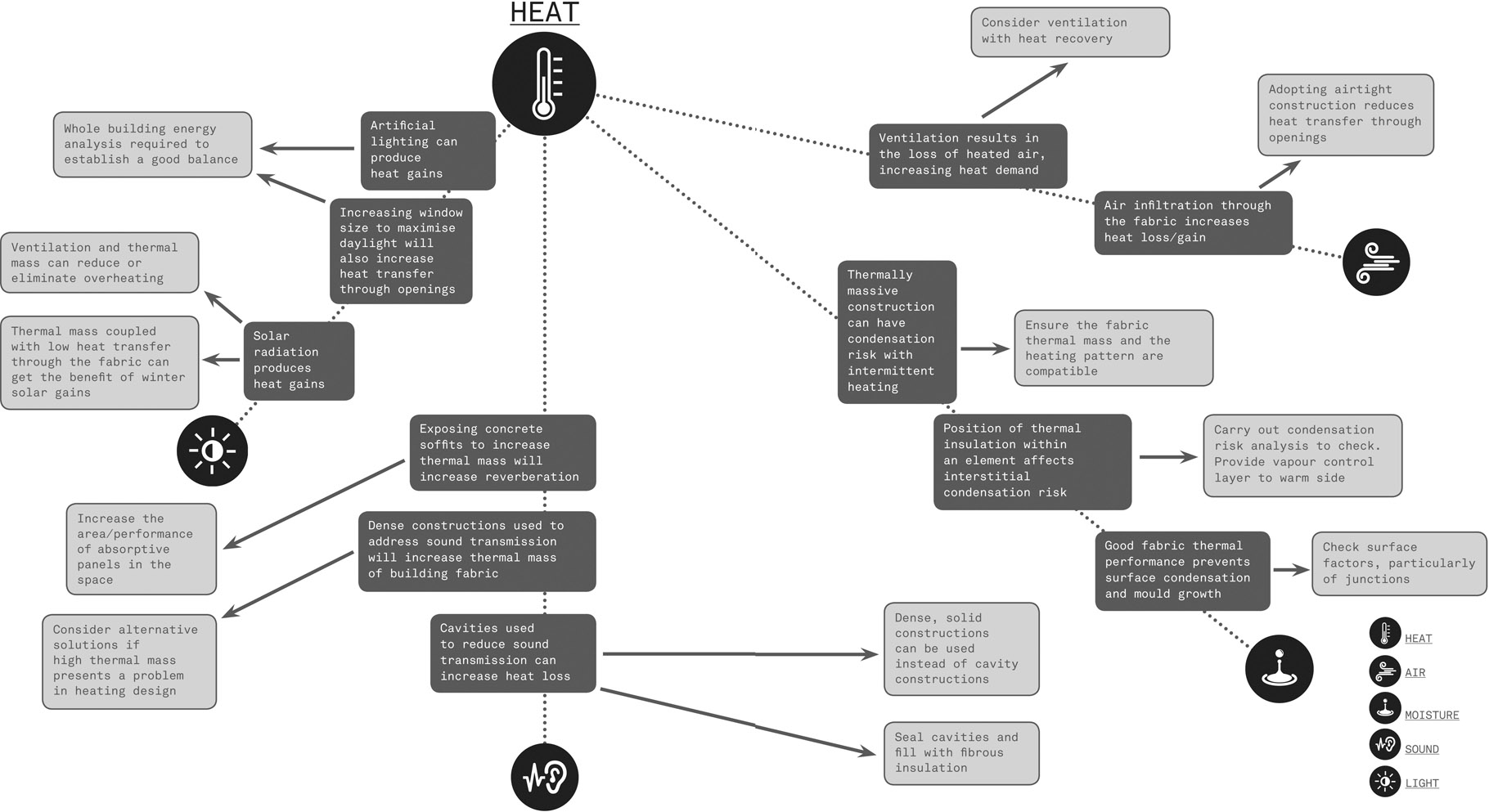
Interactions with heat