
Chapter
14
Converged Networking
TOPICS COVERED IN THIS CHAPTER:
- The two dominant data center networks
- Storage network requirements
- Data center bridging/converged enhanced Ethernet
- Lossless networks
- Congestion notification
- Enhanced transmission selection
- Fibre Channel over Ethernet
 This chapter covers the two dominant networks that exist in just about all data centers: Ethernet and Fibre Channel. You'll learn how you can build more-efficient data centers by collapsing these two networks together. You'll also learn about the specific characteristics that storage traffic requires from a network, and how traditional Ethernet fell short of these requirements. Then you'll see the major changes that were implemented in a new version of Ethernet that is variously called either data center bridging (DCB) or converged enhanced Ethernet (CEE). This chapter also discusses how Fibre Channel frames are encapsulated and transported over these new DCB/CEE networks. And the chapter concludes with how this impacts storage network design and how it is being implemented in the real world.
A Tale of Two Networks
Most data centers have at least two major networks:
- Ethernet network
- Fibre Channel network
Let's take a quick look at each of them.
Ethernet
Ethernet is the general-purpose, jack-of-all-trades network. It is the king of both versatility and scalability and is the most commonly deployed network in the world. In fact, you're unlikely to see any data center on the planet that doesn't deploy at least one Ethernet network. Most data centers deploy multiple.
On the downside, Ethernet networks aren't deterministic when it comes to performance, particularly latency. However, the recent 10G and 40G Ethernet technologies have gone some way toward addressing the performance issues of Ethernet.
Ethernet is also what we call a lossy network. Lossy tells us that when the going gets tough, Ethernet starts dropping frames. It does this during conditions such as congestion, when a switch is receiving frames but can't forward them yet because the next hop is busy. When packet loss like this happens, it's the job of protocols higher in the stack, such as Transmission Control Protocol (TCP), to take care of retransmitting frames that never reach their destination.
It is important to understand how terminology is used, both in this chapter and in the real world. Dropping packets is sometimes referred to as discarding packets. And lossy networks are often referred to as being unreliable networks. We also often interchange the terms frame and packet. Some people will argue that frames are layer 2 constructs, whereas packets are layer 3 constructs, but for our purposes both terms mean the same thing.
In summary, while not the most performant network technology in the world, Ethernet is almost certainly one of the most versatile and widely deployed.
Fibre Channel
Fibre Channel (FC) networks are high-speed, low-latency networks that are almost exclusively used for transporting storage traffic. It's extremely rare to see Fibre Channel used for anything other than storage networking. FC also operates link-layer signaling that communicates buffer credits and status, enabling it to be a lossless networking technology, meaning it doesn't drop packets as a result of congestion. This combination of low latency and lossless capability makes FC ideal for transporting SCSI traffic that doesn't deal well with unreliable transports.

At a high level, when we talk about link-layer technologies, such as buffer credit systems used to ensure lossless networks, we're talking about point-to-point technologies and not end-to-end technologies. By point-to-point, we mean between two connected devices such as an HBA-to-switch connection or a switch-to-switch connection with no other devices in between, whereas end-to-end technologies are usually initiator-to-target with potentially many devices in between.
On the downside, FC networks are less versatile and less scalable than Ethernet networks, not to mention more expensive. But they are reliable. In fact, the word channel in Fibre Channel is significant. The term comes, at least in part, from the fact that SCSI is a form of channel technology, and channel technologies are a bit different from network technologies. The main goal of channel technologies is to provide high-performance, low-overhead interconnects, whereas the main goal of networking technologies is often to provide versatility and scalability. Fibre Channel is obviously an attempt at providing both low latency and scalability. It does a decent job, but it is nowhere near as scalable as a pure networking technology like Ethernet. Ultimately, FC provides a high-speed, low-latency storage network (a channel) that is relatively contention free.
Single Converged Data Center Network
The existence of two physically and logically separate networks—Ethernet and Fibre Channel—creates a good opportunity for consolidation. That's exactly what converged networking is all about: reducing cost through infrastructure rationalization and consolidation. The following are some of the obvious benefits of consolidating Ethernet and Fibre Channel networks:
- Reducing the number of network adapters in physical servers
- Reducing the number of cables coming out of each physical server
- Reducing the number of switches in the infrastructure
So instead of having one set of network adapters, cables, and switches dedicated to Fibre Channel and another set of adapters, cables, and switches dedicated to Ethernet, with a converged network we have only a single set of network adapters, cables, and switches and run our Ethernet and FC storage traffic over them. That pretty much promises to make the wire once ideal a reality. You just rack a server on day one with a converged network adapter (CNA) in it, and you can do any and all the networking you want. You can do general-purpose IP networking, FC storage networking, iSCSI storage, NAS, maybe even low-latency, high-performance computing. A single network adapter and a single cable will do it all!
These reductions have benefits, especially in large data centers and data centers deploying densely packed servers. As data center racks become more and more densely populated with servers and storage, the prospect of reducing the number of network adapters, cables. and switches suddenly becomes very appealing. It also has the positive effect of reduced power and cooling costs. All in all, it delivers reduced data center running costs and lower total cost of ownership (TCO).
However, as is so often the case, it's not as simple as just slapping your FC storage traffic on any old Ethernet network. There are specific requirements that, if not addressed, will make your life as a storage administrator very difficult. Let's take a look at these requirements.
Storage Network Requirements
It's easy to forget that the main job of FC, as a storage networking technology, is to facilitate the reliable and efficient transportation of SCSI commands between initiators and targets. It also emulates, as much as possible, the old internal SCSI bus that is what the SCSI protocol was originally designed to work with.
Let's recap a little on SCSI. SCSI (Small Computer System Interface) was originally designed to be used within the confines of a physical server chassis, running uncontested over relatively short parallel cables. Uncontested indicates that no other protocols or traffic are contending for the same bandwidth. There is literally zero contention. As a result, SCSI was not designed to deal well with delays, congestion, or transmission errors. In fact, when these occur, SCSI deals with them very poorly. So the aim of the game is to avoid them at all costs.
One of the reasons that Fibre Channel works so well at transporting SCSI traffic is that it possesses certain features and characteristics that provide an experience similar to a local SCSI cable inside a server chassis. Some of these features and characteristics include the following:
- Simple topologies
- Good bandwidth
- Low latency
- Reliability (lossless)
- Deterministic performance
Traditional Ethernet, on the other hand, isn't such a good match for SCSI. To start with, congestion is commonplace on Ethernet networks. When contention is present, you can kiss goodbye any hopes of deterministic performance or low latency. As mentioned earlier, Ethernet networks are also lossy—they drop frames when congestion occurs. None of this bodes well for SCSI.
In summary, you certainly won't be simply wrapping your FC frames inside regular Ethernet frames and dropping them on your existing gigabit Ethernet network. Clearly something has to change in order for Ethernet to be a viable transport for FC storage traffic!
Enhanced Ethernet
In order to create a single data center network capable of transporting IP and FC storage traffic, Ethernet had to be significantly enhanced and upgraded. These changes are so extensive that many people feel it barely resembles the Ethernet that most of us cut our networking teeth on.
Sometimes we refer to the data center network as a unified fabric. Both terms mean basically the same thing: a single network that can transport LAN and SAN traffic.
To create this new enhanced Ethernet, the Institute of Electrical and Electronic Engineers (IEEE) formed a new task group within the 802.1 working group. This new task group is called the Data Center Bridging (DCB) task group and is responsible for the development of a data center Ethernet network that is capable of transporting all common data center network traffic types:
- IP LAN traffic
- FC storage traffic
- InfiniBand high-performance computing traffic
Depending on who you speak to, this enhanced Ethernet is usually called either data center bridging (DCB) or converged enhanced Ethernet (CEE). We also sometime call it a data center fabric or unified fabric.
If CEE wants to transport FC storage traffic, it needs a bunch of enhancements, including the following:
- Increased bandwidth
- Classes of service
- Priorities
- Congestion management
- Enhanced transmission selection (ETS)
Throw on top of these logical changes a whole load of new hardware requirements—cables, network adapters, switch ports, and switches—and you could be forgiven for wondering whether it's worth it. Let's go through the individual enhancements that we previously listed.
Increased Bandwidth
In order to meet the bandwidth and other demands of a unified data center fabric, CEE is a collision-free, full-duplex network that operates at a minimum of 10 Gbps. This is vital if we want to consolidate multiple 1 Gbps LANs and 2 Gbps and 4 Gbps SANs onto a single wire. 10G CEE can also safely transport 8 Gbps FC traffic, as well as allowing the entire 10Gbps of link bandwidth to be used by the latest-generation CNAs.
10 Gbps enhanced Ethernet is only the start. 40 Gbps Ethernet and 100G Ethernet are already here, and in time both will be affordable. A strong technology road map like this positions Ethernet well as the data center network of the future.
Priorities and Classes of Service
I mentioned earlier that FC storage traffic requires a lossless network. But what exactly is a lossless network? Stated very simply, a lossless network doesn't drop frames because of congestion. This is the opposite of a lossy network, which does drop frames, usually when congestion occurs. Consider the following high-level and oversimplified example: A switch receives 100 frames but is unable to immediately forward them because the switch at the next hop is saturated and unable to accept more frames. As a result, the switch buffers the 100 frames, and congestion arises. After the switch's buffers are full, it can't accept any more frames and starts to discard (drop) them.
The way that networks generally implement lossless behavior is via link-layer signaling that keeps track of buffers at the remote end. We usually call this flow control. As an example, in the FC world, flow control is implemented via a link-layer system called buffer-to-buffer (B2B) flow control, where the sender is not allowed to send frames unless it explicitly knows that the receiver has enough buffers to receive the frames. It's simple and effective at ensuring that congestion does not arise and that packets are not dropped. FC flow control is shown in Figure 14.1.
The Data Center Bridging task group has decided to implement link-layer flow control in CEE via a mechanism called priority-based flow control, or PFC for short.

In some older documentation, you may find PFC referred to as per priority pause or class-based flow control.
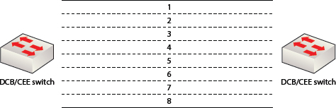
Before we dig into PFC, it is worth taking a moment to briefly talk a little about Ethernet priorities. CEE defines eight priorities that allow for eight classes of service at the link layer. This is done by tagging frames with an encoded priority, effectively allowing the bandwidth of a CEE network to be divided into eight logical lanes, or virtual links. Figure 14.2 shows a link between two CEE switches divided into eight logical lanes, labelled 1 through 8.

Now that you understand about the eight priorities in a CEE network, let's take a look at how PFC works. PFC leverages these eight logical lanes (priorities) and can selectively enforce a PAUSE condition for each of the lanes. This done by issuing a special PFC PAUSE frame on the network, specifying the following:
- Which of the lanes the PAUSE condition applies to
- How long the PAUSE condition is to last
By issuing PAUSE frames that instruct all but one lane to stop sending, you have effectively prioritized the lane that has not been paused. Likewise, if you enforce the PAUSE condition on a single lane, you have effectively de-prioritized that lane and prioritized all other lanes. Figure 14.3 shows the eight logical lanes of CEE with all lanes paused except lane 3.

It is also possible to selectively remove the PAUSE condition, such as if the congestion has dissipated sooner than expected, and there is no need to wait until the pause time-out expires.
Congestion Management
Congestion management is a way of trying to avoid network congestion, hopefully at the source, before it starts causing problems on the network. Common approaches to congestion management include rate-limiting and selectively pausing frame transmission. However, trying to solve the problem of congestion in large networks is a huge task and one that's fraught with danger. It is possible for congestion management systems to make things worse. To date, none of the attempts at standardizing congestion notification have been overly popular.
Enhanced Transmission Selection
Enhanced transmission selection (ETS) is an attempt to standardize quality of service (QoS) on CEE networks. ETS allows network bandwidth to be sliced and diced among the eight classes of service defined by CEE. This bandwidth allocation is dynamic, meaning that if a particular class of service isn't using its full allocation of bandwidth, its spare allocation is available for other classes to borrow. However, as soon as the allocated bandwidth is required by the class to which it is assigned, other classes that are borrowing bandwidth have to give it back.
This dynamic allocation and reallocation of bandwidth allows for intelligent use of available resources and is a huge improvement over previous models in which different classes of traffic had their own fixed bandwidth allocations with no ability to share.
Data Center Bridging Capability Exchange
With all the new features and configuration options that come with CEE and FCoE (which we'll talk about in the next section), life would be a lot easier if there was a simple, automated, and effective mechanism for negotiating and configuring these options. For example, as new devices are added to a CEE network, it would be great to be able to automatically negotiate which capabilities and options this newly added device supports. It would also be great to have the ability to push standard configurations to these newly added devices. With all of this in mind, Data Center Bridging Capability Exchange Protocol (DCBX) was devised.
Devices can use DCBX to issue configurations to other devices in the network such as CNAs and other switches. This can make network administration simpler by allowing for central management of configurations as well as reducing the chance of misconfiguration.
DCBX is a standards-based extension of the Link Layer Discovery Protocol (LLDP).
PFC and ETS are both examples of link-layer features that can be negotiated and configured via DCBX. After all, there wouldn't be much point in a switch issuing PFC configuration and instructions to a newly attached CNA if the CNA did not support or understand PFC.
Fibre Channel over Ethernet
Fibre Channel over Ethernet (FCoE) is literally what it says on the package: Fibre Channel frames delivered over an Ethernet network. To put it in slightly more technical terms, Fibre Channel frames are statelessly encapsulated within layer 2 Ethernet frames and transported over an IEEE 802.3 wired Ethernet network.
How do Fibre Channel and Ethernet interact with each other? As far as Ethernet is concerned, FCoE is no different from any other upper-layer protocol (ULP) such as IP or MPLS. As such, Ethernet is happy to transport FCoE traffic. On the flip side, as far as Fibre Channel is concerned, Ethernet is just a new physical transport medium, replacing the lower layers of the FC stack, FC-0 and FC-1.
The FCoE standards are driven by the International Committee for Information Technology Standards (INCITS) T11 technical committee. This T11 technical committee is the same one that defines the FC standards.
In order for an FC frame to be delivered over an Ethernet network—remember, it has to be a CEE Ethernet network—the FC frame has to be encapsulated within an Ethernet frame. Let's take a look at encapsulation.
FCoE Encapsulation
Each and every FC frame is slightly more than 2 KB in length. However, standard Ethernet frames are only 1.5 KB in length. It doesn't take a rocket scientist to figure out you can't fit 2 KB inside 1.5 KB. So something needs to be done. There were two obvious options available to the guys defining the FCoE standards:
- Fragment FC frames
- Use larger Ethernet frames
From a performance and simplicity perspective, fragmenting frames should be avoided at all costs. Fragmentation adds complexity and overhead to the encapsulation process that ultimately results in latency and lower performance. That's not good for FC storage traffic.
Using larger Ethernet frames requires the use of an Ethernet technology called jumbo frames that allows Ethernet frames to be up to 9 KB in size. Clearly, jumbo frames up to 9 KB are more than capable of encapsulating 2 KB FC frames without having to resort to fragmentation. This allows the encapsulation process to be kept as simple, lightweight, and fast as possible—one FCoE frame for every FC frame. There is no fragmentation and reassembly overhead, so there is no unnecessary protocol-related latency. All of this is important for transporting FC storage traffic. So for these reasons, the standards body decided on option 2, using jumbo frames.
The Storage Networking Industry Association (SNIA) defines baby jumbo frames as frames that are 2.5 KB in length and states that FCoE encapsulation requires at least baby jumbo (2.5KB) Ethernet frames.
Now let's look a little closer at the FCoE encapsulation process.
FC exists to transmit SCSI data, and SCSI commands and data are already encapsulated within FC frames, as shown in Figure 14.4.

FCoE takes this encapsulation one step further by adding a layer of encapsulation—encapsulating FC frames within FCoE frames, as shown in Figure 14.5.

This encapsulation of FCoE frames is a hop-by-hop process, meaning that each and every FCoE switch in the network has to strip off the FCoE encapsulation on receipt of an FCoE frame and then re-encapsulate the frame before forwarding it on to the next hop. If this isn't done quickly and efficiently, it will quickly start to impact performance. For this reason, CNAs perform this encapsulation in hardware on an ASIC, as do most FCoE switches.
There are software FCoE stacks out there, allowing you to do FCoE without needing expensive specialized CNAs. Obviously, this design requires the use of host resources such as CPU cycles to perform the FCoE processing. Although iSCSI has very much gone down the route of the software iSCSI initiator rather than the hardware iSCSI initiator, iSCSI is almost always deployed on a far smaller scale than FC (and consequently FCoE). While not necessarily recommended for production use cases, especially with high performance requirements, a software FCoE stack can be useful for labs and test environments. In vSphere 5, VMware introduced a software FCoE adapter that works with certain certified 10G cards. This can be a great way of playing around with FCoE in the lab, as long as you have FCoE-capable switches in the lab.
There is one final but critical point regarding FCoE encapsulation. The FCoE encapsulation process leaves the FC frame intact. Things like Source_ID (S_ID), Destination_ID (D_ID), and world wide port names (WWPNs) are untouched. This means that FCoE doesn't do away with existing FC concepts and mechanisms such as zoning, WWPNs, and the Simple Name Server. These all remain unchanged, allowing us to continue using the familiar FC zoning concepts we've been using for years.
It's worth explicitly pointing out that FCoE does not involve IP. In FCoE environments, FC frames are not encapsulated within IP packets. FC frames are encapsulated within layer 2 Ethernet frames, meaning that FCoE networks are large, flat, layer 2, nonroutable networks. FCoE frames cannot be routed by IP at layer 3. This is in contrast to iSCSI, which is SCSI encapsulated within IP packets and is routable at layer 3 by IP.
Converged Network Adapters
Traditional Ethernet networks are accessed via a network adapter called a network interface card (NIC). Each host that wants to connect to the Ethernet network needs at least one. Conversely, traditional Fibre Channel networks are accessed via a network adapter called a host bus adapter (HBA) in each host. Accessing an FCoE network requires a new type of network adapter called a converged network adapter (CNA). All three of these network adapter cards are implemented as PCI adapter cards. They can be either expansion cards or directly on the motherboard of a server in what is known as LAN on motherboard (LOM).
A CNA is exactly what the name suggests: a NIC and an HBA converged into a single network card. For performance reasons, CNAs provide NIC and HBA functionality in hardware (usually an ASIC) so that things like FCoE encapsulation can be fast without impacting host CPU resources.
Now let's look at how CNAs enable infrastructure consolidation. In a traditional data center with distinct Ethernet and FC networks, it's not uncommon for physical servers to have at least the following network cards:
- Two 1 Gbps Ethernet NICs for your production network
- Two 1 Gbps Ethernet NICs for vMotion
- Two 8 Gbps FC HBAs for storage
- Two 1 Gbps Ethernet (dedicated for management traffic)
Eight network cards obviously require eight cables. That's just cables. Having independent Ethernet and FC networks requires a lot of networking hardware too. You need dedicated Ethernet switches and dedicated FC switches. However, with a converged data center network, the number of network cards in the same server can easily be reduced as follows:
- Two 10 Gbps CNA
- One 1 Gbps NIC (dedicated for management traffic)
The two 10 Gbps CNAs can handle all IP and FC traffic requirements.
In order to converge networks, one concern that you may need to get over is the notion of sharing a single CNA for multiple functions. Some organizations have strict policies over network adapter isolation, where a dedicated network adapter card is used for each application. So a server with two applications would have two NICs, plus a separate NIC for management, and so on. This mindset will have to be overcome if you are to converge networks, as you'll be running FC and IP over the same network adapter!
Of course, CNAs tend to be more expensive than NICs, though not too dissimilar to HBAs.
FCoE and Lossless Network Capability
As FCoE is carrying encapsulated FC frames, it requires a lossless network. If the network/transport isn't lossless, recovery and retransmission would have to be handled by SCSI, and that wouldn't be good. SCSI was never designed to be good at recovery.
As mentioned earlier in the chapter, CEE defines eight logical lanes that allow us to create eight potential classes of service at the link layer by tagging frames with an encoded priority. For example, FCoE frames can be tagged with a priority of 3, effectively assigning FCoE frames to lane 3, or class of service 3. This priority can then be utilized by CEE technologies such as PFC to ensure that FCoE frame delivery can be prioritized or de-prioritized when congestion occurs.
Setting a priority (class of service) is usually done by setting the service priority bit in the VLAN tag.
Let's look at a quick example. Figure 14.6 shows a network with two FCoE switches. The link between the two FCoE switches is divided into eight lanes (priorities), and the network is experiencing congestion as a result of extremely high traffic over lane 2. As you can see in Figure 14.7, the network has issued a PFC PAUSE condition onto lane 2—effectively de-prioritizing it, and prioritizing all other seven lanes. This has the benefit of allowing our FCoE frames on lane 3 to continue being delivered and gives the network a chance of recovering from the congestion.

In Figure 14.7, PFC selectively applies the PAUSE condition to lane 2. This PAUSE condition tells lane 2 to stop transmitting frames for a certain period of time. Once this period of time has elapsed, frames can again be transmitted on lane 2. It is also possible for the network to remove the PAUSE condition if the congestion dissipates before the PAUSE has expired.
Although CEE contains specifications for congestion notification, this is not needed for FCoE. In an FCoE network, flow control is handled by PFC and not FC buffer credit systems.
FCoE Switches
With all of the new technologies in CEE and FCoE, it is inevitable that new switches will be required. Fortunately, there are plenty already available in the market from several vendors.
An FCoE switch connects to the LAN and the SAN. It has both CEE ports and FC ports. This is useful for companies that already have significant investment in FC SAN technology, as it allows FCoE switches to be seamlessly added into the existing SAN environment. Figure 14.8 shows an FCoE switch connected to both the corporate LAN and corporate SAN.

Although FCoE frames are transported over CEE networks, the forwarding of FCoE frames is not the responsibility of Ethernet forwarding. This means that the typical Ethernet layer 2 multipathing technologies such as Spanning Tree Protocol (STP), EtherChannel, and Transparent Interconnection of Lots of Links (TRILL) have no influence over the forwarding of FCoE frames. Instead, FCoE forwarding is the responsibility of a function in the FCoE switch known as the FCoE Forwarder (FCF). The FCF forwards FCoE frames based on the FC Destination_ID (D_ID) field of the encapsulated FC frame, as well as a routing table created by the Fabric Shortest Path First (FSPF) protocol.
FCoE in the Real World
As with most technologies, people like to kick the tires a little before deploying them in their production estates that support their most important applications and data. Also, as IT budgets are getting tighter and tighter, most organizations simply don't have the capital to be able to rip and replace existing Ethernet and FC networks with shiny new FCoE networks—even if they bring long-term cost benefits. As a result, uptake of FCoE in the real world has been lukewarm at best.
Those who have deployed FCoE have usually deployed it in either or both of the following two ways:
- As part of a prepackaged converged computing network and storage package
- At the access layer (the first hop between host and access layer switches, such as Top of Rack)
Prepackaged products include so-called converged blocks or converged pods, such as VCE Vblock or NetApp FlexPod. In these packages, you buy the entire stack of computing, network, and storage as a single packaged product. These blocks tend to come with servers that have CNAs and boot from FCoE SAN storage. You often don't have the choice of how to configure them and are forced to deploy CNAs in your servers and FCoE switches at that first hop from the server to the Top of Rack switch (not that this pre-scripted design is always a bad thing).
The other major area where people are deploying FCoE is at the access layer of the network. This means the first hop onto the network, between the network adapter in the server and the access-layer network switch that usually sits at the top of the same rack in which the server is installed. This is shown in Figure 14.9.

The access layer of the network is a natural and good place to start deploying any new technology. For starters, it's far less risky to deploy a new technology at the network access layer than it is to drop it right in at the core. Deploying at the access layer allows you to slowly and systematically deploy FCoE—one rack at a time—and gain confidence in the technology before starting to deploy deeper within the network.
As a result, most deployments of FCoE, other than the likes of NetApp FlexPod and VCE Vblock, tend to be at the network access layer by deploying new servers with CNAs instead of NICs and HBAs. This reduces the network-related cabling and the number of network switches in the rack. Deploying CNAs in your servers is also future-proofing your servers against any future FCoE deployments, as the CNAs can start today doing just 10G Ethernet, but if you deploy FCoE in the future, you can also deal with FCoE.
Another consideration when deploying FCoE in the real world relates to who owns the converged infrastructure. Who owns the CNAs, and usually more important, who owns the FCoE switches? The following should be considered when making this decision:
- Who decides which FCoE switches to purchase—vendor and model?
- Who pays for the switches and the support?
- Who decides when and what versions of firmware to deploy?
- Who has root access to switches?
These are not always easy decisions. In most organizations, the trend seems to be toward the server team owning the CNAs, and the network team owning the FCoE switches, with the storage guys providing the expert advice on the configuration of CNAs and FCoE and FC settings within the FCoE switches.
Although FCoE is somewhat complementary and similar to server virtualization, it has to be pointed out that uptake of FCoE has been nothing like the uptake of server virtualization. This is in no small part because FCoE hasn't brought anywhere near the kind of flexibility and agility that server virtualization has. In fact, if anything, software-defined networking (SDN) looks more likely to bring the kind of revolutionary flexibility and new models similar to those brought with server virtualization technologies.
Summary
This chapter covered the two dominant networking technologies seen in most data centers around the world: Ethernet and Fibre Channel. You learned about the differences between them as well as the potential benefits of combining them into a single data center network. The chapter showed how Ethernet was the natural choice, because of its wider adoption and increased versatility and flexibility. The chapter also outlined the features that were lacking in Ethernet in order to make it a viable transport for storage traffic and then went on to detail how major changes have been implemented into a new version of Ethernet—known as data center bridging (DCB), or converged enhanced Ethernet (CEE)—that make it suitable or transporting storage traffic. You then learned how FC is layered on top of DCB/CEE, and finished the chapter seeing how this impacts future network design as well as how this is being implemented in the real world today.
Chapter Essentials
Data Center Bridging Data center bridging (DCB) is a task group within the Institute of Electrical and Electronic Engineers (IEEE) 802.1 working group. The task group is responsible for implementing enhancements to 802.1 networks to enable them to be the natural choice for future data center networks. The version of enhanced Ethernet that the DCB task group is responsible for is sometimes called DCB Ethernet.
Converged Enhanced Ethernet Converged enhanced Ethernet (CEE) is a new enhanced version of Ethernet suitable for transporting storage traffic as well as traditional IP traffic. This makes it a natural choice for data center network consolidation.
Lossless Networks Lossless networks don't drop frames when congestion occurs. This is a key network feature for any network wishing to transmit FC traffic.
Fibre Channel over Ethernet Fibre Channel over Ethernet (FCoE) is the encapsulation of Fibre Channel frames within Ethernet frames, allowing Fibre Channel traffic to be transported over converged enhanced Ethernet networks. FCoE is an important technology in enabling data center network consolidation.