
1
Introduction
1.1 Background
Automatic modulation classification (AMC) was first motivated by its application in military scenarios where electronic warfare, surveillance and threat analysis requires the recognition of signal modulations in order to identify adversary transmitting units, to prepare jamming signals, and to recover the intercepted signal. The term ‘automatic’ is used as opposed to the initial implementation of manual modulation classification where signals are processed by engineers with the aid of signal observation and processing equipment. Most modulation classifiers developed in the past 20 years are implemented through electronic processors. During the 1980s and 1990s there were considerable numbers of researchers in the field of signal processing and communications who dedicated their work to the problem of automatic modulation classification. This led to the publication of the first well received book on the subject by Azzouz and Nandi (1996). The interest in AMC for military purposes is sustained to this very day.
The beginning of twenty-first century saw a large number of innovations in communications technology. Among them are few that made essential contributions to the staggering increase of transmission throughput in various communication systems. Link adaptation (LA), also known as adaptive modulation and coding (AM&C), creates an adaptive modulation scheme where a pool of multiple modulations are employed by the same system (Goldsmith and Chua, 1998). It enables the optimization of the transmission reliability and data rate through the adaptive selection of modulation schemes according to channel conditions. While the transmitter has the freedom to choose how the signals are modulated, the receiver must have the knowledge of the modulation type to demodulation the signal so that the transmission can be successful. An easy way to achieve that is to include the modulation information in each signal frame so that the receivers would be notified about the change in modulation scheme, and react accordingly. However, this strategy affects the spectrum efficiency due to the extra modulation information in each signal frame. In the current situation where the wireless spectrum is extremely limited and valuable, the aforementioned strategy is simply not efficient enough. For this reason, AMC becomes an attractive solution to the problem. Thanks to the development in microprocessors, receivers nowadays are much enabled in terms of their computational power. Thus, the signal processing required by AMC algorithms becomes feasible. By automatically identifying the modulation type of the received signal, the receiver does not need to be notified about the modulation type and the demodulation can still be successfully achieved. In the end, spectrum efficiency is improved as no modulation information is needed in the transmitted signal frame. AMC has become an integral part of intelligent radio systems, including cognitive radio and software-defined radio.
Over the years, there have been many terms used to describe the same problem: modulation recognition, automatic modulation recognition, modulation identification, modulation classification, and automatic modulation classification. There are other names for the problem, such as PSK (phase-shift keying modulation) classification and M-QAM (M-ary quadrature amplitude modulation) classification that have a more specific target but which still operate under the same principle of automatic modulation classification. In this book, we have decided to use automatic modulation classification and AMC as a consistent reference to the same problem.
1.2 Applications of AMC
Having discussed the possible use of AMC in both military and civilian scenarios, in this section we take a close look at how AMC is incorporated in different military and civilian systems.
1.2.1 Military Applications
AMC has an essential role in many military strategies. Modern electronic warfare (EW) consists of three major components: electronic support (ES), electronic attack (EA) and electronic protect (EP) (Poisel, 2008). In ES, the goal is to gather information from radio frequency emissions. This is often where AMC is employed after the signal detection is successfully achieved. The resulting modulation information could have several uses extending into all the components in EW. An illustration of how a modulation classifier is incorporated in the military EW systems is given in Figure 1.1.
Figure 1.1 Military signal intelligence system.
To further the process of ES, the modulation information can be used for demodulating the intercepted signal in order to recover the transmitted message among adversary units. This is of course completed with the aid of signal decryption and translation. Meanwhile, the modulation information alone can also provide vital information to the electronic mapping system where it could be used to identify the adversary units and their possible locations.
In EA, jamming is the primary measure to prevent the communication between adversary units. There are many jamming techniques available. However, the most common one relies on deploying jammers in the communication channel between adversary units and also transmitting noise signals or made-up signals using the matching modulation type. To override the adversary communication, the jamming signal must occupy the same frequency band as the adversary signal. This information is available from the signal detector. The power of the jamming signal must be significantly high, which is achieved by using an amplifier before transmitting the jamming signal. More importantly, the jamming signal must be modulated using the modulation scheme detected by the modulation classifier.
In EP, the objective is to protect friendly communications from adversary EA measures. As mentioned above, jammers transmit higher power signals to override adversary communication in the same frequency band. The key is to have the same signal modulation. An effective strategy to prevent friendly communication being jammed is to have awareness of the EA effort from adversary jammers and to dodge the jamming effort. More specifically, the friendly transmitter could monitor the jamming signal’s modulation and switch the friendly unit to a different modulation scheme to avoid jamming.
1.2.2 Civilian Applications
In the civilian scene, AMC is most important for the application of LA. As demonstrated in Figure 1.2, the signal modulator in the LA transmitter is replaced by an adaptive modulation unit. The role of the adaptive modulator is to select the modulation from a predefined candidate pool and to complete the modulation process. The selection of modulation from the candidate pool is determined by the system specification and channel conditions. The lower-order and more robust modulations such as BPSK (binary phase-shift keying modulation) and QPSK (quadrature phase-shift keying modulation) are often selected when the channel is noisy and complex, given that the system requires high link reliability. The higher-order and more efficient modulations such as 16-QAM (16-quadrature amplitude modulation) and 64-QAM (64-quadrature amplitude modulation) are often selected to satisfy the demand for high-speed transmission in clear channels. The only communication between adaptive modulation module and the receiver is completed at system initialization where the information of the modulation candidate pool is notified to the receiver. During normal transmission the adaptive modulator embeds no extra information in the communication stream. At the receiving end of the LA system, channel estimation is performed prior to other tasks. If the channel is static, the estimation is only performed at the initial stage. If the channel is time variant, the channel state information (CSI) could be estimated regularly throughout the transmission. The estimated CSI and other information would then be fed back to the transmitter where the CSI will be used for the selection of modulation schemes. More importantly, the CSI is required to assist the modulation classifier. Depending on the AMC algorithm, different channel parameters are needed to complete the modulation classification. Normally, the accuracy of channel estimation has a significant impact on the performance of the modulation classifier. The resulting modulation classification decision is then fed to the reconfigurable signal demodulator for appropriate demodulation. If the modulation classification is accurate, the correct demodulation method would capture the message and complete the successful transmission. If the modulation classification is incorrect, the entire transmission fails as the message cannot be recovered from the demodulator. It is not difficult to see the importance of AMC in LA systems.
Figure 1.2 AMC in link adaptation system.
1.3 Field Overview and Book Scope
Given the importance of AMC in various military and civilian communication applications, there has been a large amount of research work dedicated to the problem of AMC in a wide variety of settings. The nature of the problem creates multiple dimensions in its solutions and inspires continuous contribution from generations of researchers.
First, the modulation classifier needs to be accurate. The accuracy is measured by the percentage of errors made in a number of signal frames being transmitted. The lower the error the better the classifier is perceived to be. The likelihood-based classifiers first introduced by Polydoros and Kim ( 1990) provides optimal classification accuracy given matching signal model and perfect CSI knowledge. The approach has since been indulged by many researchers and led to many likelihood classifiers with various traits (Wei and Mendel, 2000; Hameed, Dobre and Popescu, 2009; Chavali and Da Silva, 2011; Xu, Su and Zhou, 2011; Shi and Karasawa, 2012).
Second, the modulation classifier needs to be robust. Since the communication channel can be unpredictable, especially in wireless channels, the classifier needs to have consistent classification accuracy in various channel conditions. In reality, conditions like multi-path fading, shadowing, Doppler effect, and additive noise have significant impact on the classification accuracy. Most of the works on AMC consider additive white Gaussian noise (AWGN) as a standard channel condition when evaluating their algorithms (Gardner and Spooner, 1988; Nandi and Azzouz, 1998; Swami and Sadler, 2000; Wei and Mendel, 2000). However, the consideration of fading channel and impulsive noises has become necessary for practically application of an AMC algorithm and has since been featured in many recent publications (Headley and Da Silva, 2011; Chavali and Da Silva, 2013).
Third, the classifier needs to be computationally efficient. The computational cost is reflected in two aspects of system performance. A complex AMC algorithm requires more powerful hardware to support it. In addition, a complex algorithm requires a longer time to complete the classification process, which may render certain applications unsuited if real-time decisions are needed. With some of the most fundamental AMC algorithms established, we are seeing more and more works which contribute to improve the computational complexity of some state-of-the-art algorithms (Wong and Nandi, 2008; Wang and Wang, 2010; Xu, Su and Zhou, 2011). With the popularity of mobile communication, computational efficiency will remain a major consideration in the development of AMC algorithms.
Fourth, the classifier needs to be versatile. The versatility of an AMC classifier consists of many aspects. The classifier needs to handle as many modulation types as possible. The classifier needs to be operable in scenarios where limited knowledge of the channel or the communication system is available. The classifier needs to provide information other than the modulation type as by-product in real time. The classifier needs to be applicable in various communication systems such as single-input and single-output systems (SISO) and multiple-input and multiple-output systems (MIMO). The classification of both analogue and digital modulation can be effectively achieved by multiple signal features suggested by Azzouz and Nandi ( 1996). The current focus of versatility of an AMC algorithm lies in the classification of multi-ordered digital modulations in MIMO systems (Choqueuse et al., 2009; Hassan et al., 2012; Mühlhaus et al., 2013).
In this book, we focus on the more related issues in the current AMC development environment. We will revisit most of the existing AMC algorithms and sketch their implementations under a unified signal model (Chapter 2). The classifiers will be classified into five categories and presented in five chapters (from Chapters 3 to 7). As these classifiers all have their strengths and weaknesses, we will exam some of the key algorithms from each category and assess their performance in simulated environments (Chapter 8). The simulation focuses on digital modulations that are most relevant to the current communication systems. As we develop a comprehensive understanding of all the algorithms and their characteristics, in Chapters 9 and 10, we attempt to suggest designs of AMC algorithms that are tailored to some of the specific applications in civilian and military scenarios.
1.4 Modulation and Communication System Basics
To familiarize the readers with the technical concepts that are used in this book, we dedicate this section to the basics of communications theory.
1.4.1 Analogue Systems and Modulations
We assume the source signal x(t) is analogue, non-negative and continuous at time t. In analogue systems, the signal is modulated before transmission using analogue modulations. Depending on the modulation type, the modulator is preconfigured and not subject to future change. Here we consider three types of analogue modulation, namely amplitude modulation (AM), frequency modulation (FM), and phase modulation (PM). An illustration of the analogue radio communication system is given in Figure 1.3.
Figure 1.3 Analogue communication system.
For AM modulation, the signal is modulated with a carrier signal c(t) = A · cos(2πfct) with a carrier frequency fc. The source signal is multiplied by the carrier signal to create the transmitted modulation signal s(t) given by equation (1.1).
The resulting transmitted signal is called the bandpass signal where the source signal is embedded in the signal amplitude envelope. Figure 1.4 gives examples of signal waveform of the carrier signal, the source signal, and the modulation signal using AM.
Figure 1.4 (a) Carrier signal, (b) source signal and (c) AM signal.
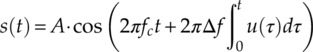
For FM modulations, the same carrier can be used. However, the source signal is added to modify the frequency component of the carrier signal. The time series FM modulation signal is given by equation (1.2),
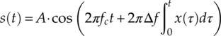
where Δf is the frequency deviation that controls the variation of the modulated signal frequency. The waveform of the FM signal is given in Figure 1.5.
Figure 1.5 (a) Carrier signal, (b) source signal and (c) FM signal.
For PM modulation, the source signal is added to the carrier signal by modifying the signal phase. The expression of the PM modulation signal is found as shown in equation (1.3).
The waveform of a PM signal is given in Figure 1.6.
Figure 1.6 (a) Carrier signal, (b) source signal and (c) PM signal.
1.4.2 Digital Systems and Modulations
Modern communication systems make less use of analogue modulations. Instead, digital modulations are well favoured thanks to a better match with digital data and stronger immunity against interference. Notable digital modulation types include amplitude-shift keying (ASK), frequency-shift keying (FSK), phase-shift keying (PSK), pulse amplitude modulation (PAM), and quadrature amplitude modulation (QAM). To meet the demand for higher transmission throughput, digital modulations of higher orders including M-ary ASK (M-ASK), M-ary FSK (M-FSK), M-ary PSK (M-PSK), M-ary PAM (M-PAM), and M-ary QAM (M-QAM) are often used. The label “M” indicates the number of samples in the modulation alphabet set.
Like the analogue systems, we have a source signal x(t). The source signal is digitized by sampling and quantization, the resulting digital signal is then coded by various means for the purpose of data security and limiting transmission errors. In the context of AMC, the digitization process and coding theory makes little impact on the classifier design and classification performance. Therefore, we neglect the details of these processes and assume the end product to be u[n] ∼ x(t), (n − 1)T < t < nT, where u[n] is the nth source signal symbol and T is the symbol timing for the digitized source signal. Depending on the modulation type, the modulated signal is generated in different ways. An illustration of the digital radio communication system is given in Figure 1.7.
Figure 1.7 Digital communication system.
For ASK modulations, the expression for the modulated signal given in equation (1.4) is very similar to that for AM, the only difference being that the source signal is digital instead of analogue.
The waveform of an ASK signal is given in Figure 1.8.
Figure 1.8 (a) Carrier signal, (b) source signal and (c) ASK signal.
For FSK modulations, the expression also matches the one from FM modulation, as shown in equation (1.5).
The waveform of an FSK signal is given in Figure 1.9.
Figure 1.9 (a) Carrier signal, (b) source signal and (c) FSK signal.
For PSK modulation, the expression is similar to the one for the PM modulation, as shown in equation (1.6).
The waveform of FSK signal is given in Figure 1.10.
Figure 1.10 (a) Carrier signal (b) source signal and (c) PSK signal.
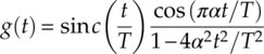
PAM modulation shares a similar principle of embedding the source signal in the amplitude of the carrier signal. However, the expression of the modulated signal, as shown in equation (1.7), differs due to the added pulse-shaping factor g(t).
The factor g(t) defines the shape of the pulse. A common example is the raised cosine frequency shaping filter, which is defined by equation (1.8), where α is the roll-off factor between 0 and 1.
QAM modulations are similar to PAM modulations and are often considered as a combination of PSK and ASK modulations. Instead of a real-valued source signal, the source signal is mapped to a complex baseband waveform, equation (1.9).
The QAM modulated signal is composed as shown in equation (1.10), where |u(t)|is the magnitude of the complex baseband signal and arg{u(t)} is the phase of the complex baseband signal.
For digital modulations, the signal is often visualized using a constellation plot where the in-phase and quadrature (I-Q) components of a signal are used to provide coordinates. Constellation plots of 2-PAM, QPSK, 8-PSK, and 16-QAM modulations are given in Figure 1.11 as examples.
Figure 1.11 Constellation plots of 2-PAM, QPSK, 8-PSK and 16-QAM.
1.4.3 Received Signal with Channel Effects
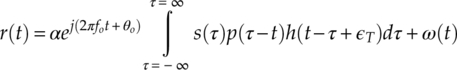
Regardless of the transmitter setting and modulation selection, the transmitted signals are subject to the same channel conditions. Here we give a signal model that includes a majority of the channel effect a single wireless radio frequency may encounter. The received signal is given by equation (1.11), where α is the channel gain, fo and θo are carrier frequency and phase offsets, s(τ) is the transmitted signal sample at time τ, p(·) is the pulse shaping, h(·) is the channel response, ɛT is the symbol timing error, and ω(·) is the additive noise. The noise level associated with ω(·) is often measured in signal-to-noise ratio (SNR). SNR is the ratio between the power of the transmitted symbols and the additive noises.
The nth discrete signal sample at time t = nT is given by equation (1.12),
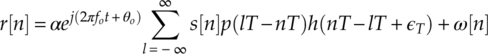
where s[n] is the nth transmitted signal sample and ω[n] is the additive noise component at t = nT.
Under common circumstances, assumptions are made that the pulse shaping and channel response is known to the receiver. Therefore, the signal model after matching the filter could be simplified as equation (1.13).
The majority of our analysis will be based on the sampled discrete signal using the above equation. More details on signal models in different channels are given in Chapter 2.
1.5 Conclusion
In this chapter, we introduce the historical background of AMC where it originated from military electronic warfare as an alternative to manual modulation classification. It is also highlighted that AMC holds an important position in modern civilian communications systems. A brief showcase of the implementation of AMC in military applications and civilian applications is given. An overview of the field of AMC study is given which leads to the scope of this book. The chapter is finished with some basic knowledge of communication systems that are considered in the remainder of the book.
References
- Azzouz, E.E. and Nandi, A.K. (1996) Automatic Modulation Recognition of Communication Signals, Kluwer, Boston.
- Chavali, V.G. and Da Silva, C.R.C.M. (2011) Maximum-likelihood classification of digital amplitude-phase modulated signals in flat fading non-gaussian channels. IEEE Transactions on Communications, 59 (8), 2051–2056.
- Chavali, V.G. and Da Silva, C.R.C.M. (2013) Classification of digital amplitude-phase modulated signals in time-correlated non-gaussian channels. IEEE Transactions on Communications, 61 (6), 2408–2419.
- Choqueuse, V., Azou, S., Yao, K. et al. (2009) Blind modulation recognition for MIMO systems. Military Technical Academy Review, XIX (2), 183–196.
- Gardner, W.A. and Spooner, C.M. (1988) Cyclic Spectral Analysis for Signal Detection and Modulation Recognition. Military Communications Conference,San Diego, CA, USA, 23–26 October 1988, pp. 419–424.
- Goldsmith, A.J. and Chua, S. (1998) Adaptive coded modulation for fading channels. IEEE Transactions on Communications, 46 (5), 595–602.
- Hameed, F., Dobre, O.A. and Popescu, D. (2009) On the likelihood-based approach to modulation classification. IEEE Transactions on Wireless Communications, 8 (12), 5884–5892.
- Hassan, K., Dayoub, I., Hamouda, W. et al. (2012) Blind digital modulation identification for spatially-correlated MIMO systems. IEEE Transactions on Wireless Communications, 11 (2), 683–693.
- Headley, W.C. and Da Silva, C.R.C.M. (2011) Asynchronous classification of digital amplitude-phase modulated signals in flat-fading channels. IEEE Transactions on Communications, 59 (1), 7–12.
- Mühlhaus, M.S., Jondral, F.K., Dobre, O.A. and Oner, M. (2013) A low complexity modulation classification algorithm for MIMO systems. IEEE Communications Letters, 17 (10), 1881–1884.
- Nandi, A.K. and Azzouz, E.E. (1998) Algorithms for automatic modulation recognition of communication signals. IEEE Transactions on Communications, 46 (4), 431–436.
- Poisel, A.R. (2008) Introduction to Communication Electronic Warfare Systems, Artech House, Norwood, MA.
- Polydoros, A. and Kim, K. (1990) On the detection and classification of quadrature digital modulations in broad-band noise. IEEE Transactions on Communications, 38 (8), 1199–1211.
- Shi, Q. and Karasawa, Y. (2012) Automatic modulation identification based on the probability density function of signal phase. IEEE Transactions on Communications, 60 (4), 1–5.
- Swami, A. and Sadler, B.M. (2000) Hierarchical digital modulation classification using cumulants. IEEE Transactions on Communications, 48 (3), 416–429.
- Wang, F. and Wang, X. (2010) Fast and robust modulation classification via Kolmogorov-Smirnov test. IEEE Transactions on Communications, 58 (8), 2324–2332.
- Wei, W. and Mendel, J.M. (2000) Maximum-likelihood classification for digital amplitude-phase modulations. IEEE Transactions on Communications, 48 (2), 189–193.
- Wong, M.L.D. and Nandi, A.K. (2008) Semi-blind algorithms for automatic classification of digital modulation schemes. Digital Signal Processing, 18 (2), 209–227.
- Xu, J.L., Su, W. and Zhou, M. (2011) Likelihood-ratio approaches to automatic modulation classification. IEEE Transactions on Systems, Man, and Cybernetics, Part C (Applications and Reviews), 41 (4), 455–469.