8
Comparison of Modulation Classifiers
8.1 Introduction
In Chapters 3–7 we listed an array of modulation classifiers. While their mechanisms are distinctly different and intriguing, we are more interested in their actual modulation-classification performance. Modulation classification may be applied in many different scenarios; the traits of a good modulation classifier are shared in most cases.
First, a modulation classifier should be able to classify as many modulation types as possible. Such a trait makes a modulation classifier easily applicable in different applications without needing any modification to accommodate extra modulations. Second, a modulation classifier should provide high classification accuracy. The high classification accuracy is relative to the different noise levels. Third, the modulation classifier should be robust in many different channel conditions. The robustness can be provided by either the built-in channel estimation and correction mechanism or the natural resilience of the modulation classifier against channel conditions. Fourth, the modulation classifier should be computationally efficient. In many applications, there is a strict limitation of computation power which may be unsuitable for over-complicated modulation classifiers. Meanwhile, some applications may require fast decision making, which requires the classification to be evaluated swiftly. Only a modulation classifier with high computational efficiency could meet this requirement. After all, a simple and fast modulation classifier algorithm is always appreciated.
In this chapter, we have tried to benchmark some of the aforementioned modulation classifiers in a simulated testing environment. The goal is to acquire the evaluation of the different traits for different classifiers and to provide a guideline for classifier selection when a specific application arises.
8.2 System Requirements and Applicable Modulations
In this section we examine the system requirements of AMC classifiers and the modulations they are able to classify. The system requirement consists of pilot sample and channel parameters the classifiers needed in order to reach a classification decision. Among them, channel gain, noise variance, carrier phase offset and carrier frequency offset have been picked as the key channel parameters that may be needed by different classifiers.
As the system requirements and applicable modulations have been mentioned in each chapter already, they are only listed again in Tables 8.1–8.5 to provide easy comparison. If the classifier requires a pilot sample for training purposes, it will be labelled “Yes” for “Pilot Samples”, otherwise “No” if not. For the channel parameters, there are three possible scenarios: “Known”, “Unknown” and “Compensated”. When the classifier requires the channel parameter to be known, it means the parameter must be estimated beforehand to complete the classification. When the channel parameter is labelled unknown, it means that the classifier can complete classification without the knowledge of the specific channel parameter. If the channel parameter is labelled compensated, it means that the classifier has the inherent ability to estimate the parameter and use it to improve the classification accuracy. For the applicable modulations, we consider a pool of the most common digital modulations including ASK, PSK, FSK, PAM and QAM. In addition, if the classifier is able to classify the same modulation with different orders, they are instead labelled as M-ASK, M-PSK, M-FSK, M-PAM or M-QAM.
Table 8.1 System requirements and applicable modulation for LB classifiers
| Pilot samples | Channel gain | Noise variance | Phase offset | Frequency offset | Modulations | |
| Chapter 3 | ||||||
| ML | No | Known | Known | Known | Unknown | M-ASK, M-PSK, M-FSK, M-PAM, M-QAM |
| ML-P | No | Known | Known | Known | Unknown | M-PSK, M-QAM |
| ML-M | No | Known | Known | Unknown | Unknown | M-ASK, M-PAM, M-QAM |
| ALRT | No | Compensated | Compensated | Compensated | Unknown | M-ASK, M-PSK, M-FSK, M-PAM, M-QAM |
| GLRT | No | Compensated | Compensated | Compensated | Unknown | M-ASK, M-PSK, M-FSK, M-PAM, M-QAM |
| HLRT | No | Compensated | Compensated | Compensated | Unknown | M-ASK, M-PSK, M-FSK, M-PAM, M-QAM |
Table 8.2 System requirements and applicable modulation for distribution test-based classifiers
| Pilot samples | Channel gain | Noise variance | Phase offset | Frequency offset | Modulations | |
| Chapter 4 | ||||||
| KS-one | No | Known | Known | Unknown | Unknown | M-ASK, M-PSK, M-FSK, M-PAM, M-QAM |
| KS-two | Yes | Known | Known | Unknown | Unknown | M-ASK, M-PSK, M-FSK, M-PAM, M-QAM |
| AD | No | Known | Known | Unknown | Unknown | M-ASK, M-PSK, M-FSK, M-PAM, M-QAM |
| CvM | No | Known | Known | Unknown | Unknown | M-ASK, M-PSK, M-FSK, M-PAM, M-QAM |
| ODST | No | Known | Known | Unknown | Unknown | M-ASK, M-PSK, M-FSK, M-PAM, M-QAM |
Table 8.3 System requirements and applicable modulation for FB classifiers
| Pilot samples | Channel gain | Noise variance | Phase offset | Frequency offset | Modulations | |
| Chapter 5 | ||||||
| Spectral-based features | No | Unknown | Unknown | Unknown | Unknown | ASK, PSK, FSK, PAM, QAM |
| Wavelet-based features | No | Unknown | Unknown | Unknown | Unknown | M-ASK, M-PSK, M-FSK, M-PAM, M-QAM |
| Cyclic cumulants | No | Unknown | Unknown | Unknown | Unknown | M-ASK, M-PSK, M-FSK, M-PAM, M-QAM |
| Moments | No | Unknown | Unknown | Unknown | Unknown | M-ASK, M-PSK, M-FSK, M-PAM, M-QAM |
| Cumulants | No | Unknown | Unknown | Unknown | Unknown | M-ASK, M-PSK, M-FSK, M-PAM, M-QAM |
Table 8.4 System requirements and applicable modulation for machine learning classifiers
| Pilot samples | Channel gain | Noise variance | Phase offset | Frequency offset | Modulations | |
| Chapter 6 | ||||||
| KNN | Yes | Unknown | Unknown | Unknown | Unknown | M-ASK, M-PSK, M-FSK, M-PAM, M-QAM |
| SVM | Yes | Unknown | Unknown | Unknown | Unknown | M-ASK, M-PSK, M-FSK, M-PAM, M-QAM |
| ANN | Yes | Unknown | Unknown | Unknown | Unknown | M-ASK, M-PSK, M-FSK, M-PAM, M-QAM |
| GA-KNN | Yes | Unknown | Unknown | Unknown | Unknown | M-ASK, M-PSK, M-FSK, M-PAM, M-QAM |
| GP-KNN | Yes | Unknown | Unknown | Unknown | Unknown | M-ASK, M-PSK, M-FSK, M-PAM, M-QAM |
Table 8.5 System requirements and applicable modulation for blind modulation classifiers
| Pilot samples | Channel gain | Noise variance | Phase offset | Frequency offset | Modulations | |
| Chapter 7 | ||||||
| EM-ML | No | Compensated | Compensated | Compensated | Unknown | M-ASK, M-PSK, M-FSK, M-PAM, M-QAM |
| MD-NPLF | No | Compensated | Unknown | Compensated | Unknown | M-ASK, M-PSK, M-FSK, M-PAM, M-QAM |
8.3 Classification Accuracy with Additive Noise
In this section we examine the classification accuracy of different classifiers against additive noise. In this scenario we assume that we have perfect channel knowledge and that any channel effect has been compensated prior to modulation classification. The signal model used is derived from equation (1.13), such that the only additive noise is considered to be given by equation (8.1),
where the noise model for ω[·] used is the additive white Gaussian noise. Nine of the most popular modulations are selected to form a candidate pool. They are 2-PAM, 4-PAM, 8-PAM, BPSK, QPSK, 8-PSK, 4-QAM, 16-QAM and 64-QAM. The symbol mappings for all modulations are demonstrated in Figure 8.1.
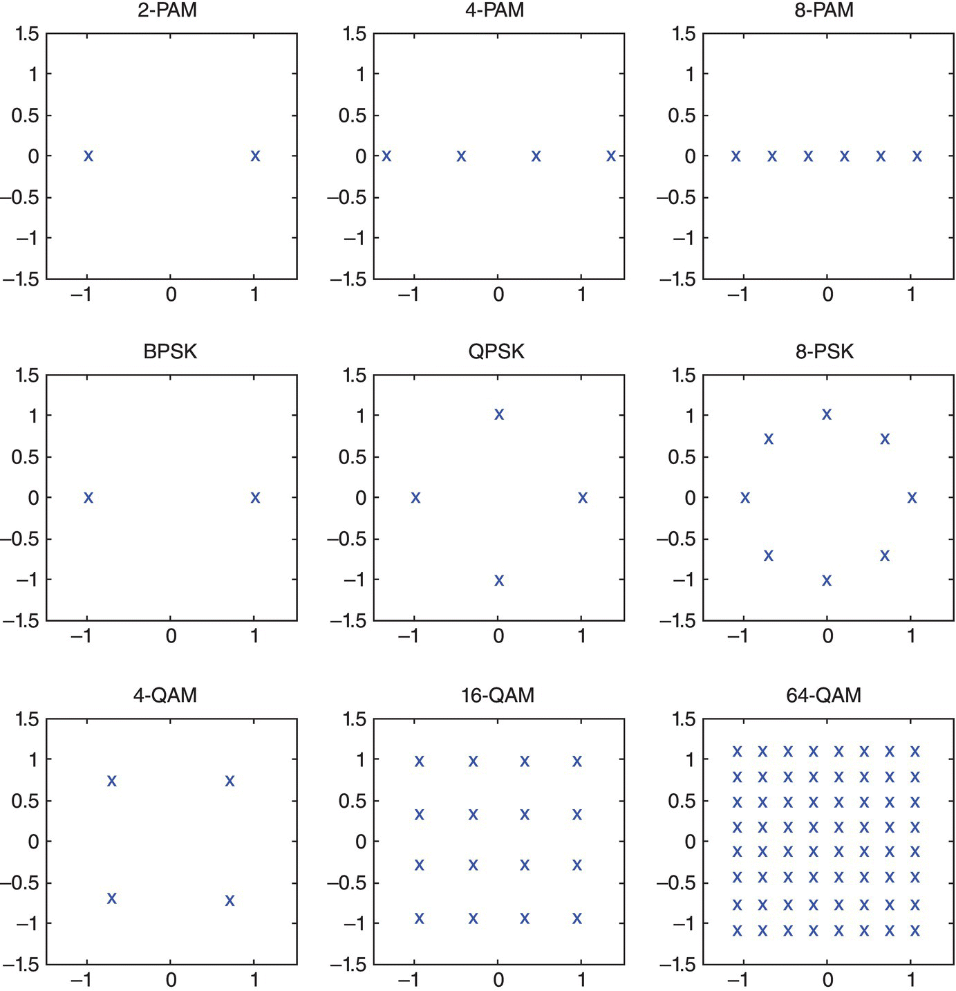
Figure 8.1 Symbol mapping for different modulations on I-Q plane.
The alphabet set from the symbol mapping for each modulation is normalized to zero mean and unit power. When simulating the transmitted signal symbols, each symbol was assigned from the alphabet set with equal probability. For each modulation, L = 1000 realizations of transmitted signals are first generated. In each signal realization, N = 1024 signal samples are sampled at the correct symbol timing without timing mismatch and timing error.
8.3.1 Benchmarking Classifiers
Among all the classifiers, we have selected a small set of classifiers to represent each category of classifier.
For likelihood-based classifiers, the maximum-likelihood classifier (Wei and Mendel, 2000) is used to investigate the performance characteristic of likelihood-based classifiers. In addition, when given perfect channel knowledge, the ML classifier is also used to establish the upper bound of classification accuracy. The likelihood function used is given by equation (3.3). The channel gain and noise variance are assumed to be known to the classifier.
For distribution test-based classifiers, the one-sample KS test classifier (Wang and Wang, 2010) is adopted to represent the distribution test-based classifiers. The channel gain and noise variance are assumed to be known to the classifier.
For feature-based classifiers, we have selected both moments and cumulants (Swami and Sadler, 2000) due to their high classification accuracy for digital modulations of different orders. The classification for both sets of features is accomplished using a KNN classifier. For each signal modulation, 30 signal realizations are generated to construct the reference feature space. No channel knowledge is used for the classification. The list of moments used includes μ20, μ21, μ40, μ41, μ43, μ60, μ61, μ62, and μ63. The list of cumulants used includes C40, C41, C43, C60, C61, C62, and C63.
For machine learning classifiers, the combination of GP and KNN is employed to utilize both the moments and cumulants feature sets. In the training state, the same training signals for the KNN classifier is used for the evaluation of feature combinations. The GP process is performed before the signal classification in the training stage in order to achieve the optimized feature selection and combination of the available features. No channel knowledge is used in the classifier.
For blind modulation classifiers, the EM-ML classifier is implemented with an EM stage that provides the joint estimation of complex channel coefficient and noise variance for each modulation hypothesis. The resulting estimates are used for the evaluation of likelihood in each hypothesis for the ML classifier.
8.3.2 Performance Comparison in AWGN Channel
In the first set of experiments we examine the robustness of different classifiers when mismatch in noise level is presented. The noise level is measured by the signal-to-noise ratio, which is defined as given in equation (8.2),

where P(s) is the power of the power of the transmitted signal, and P(ω) is the power of the AWGN noise.
From −20 to 20 dB with a step of 1 dB, the AWGN noises are generated for each signal realization according the signal power. For the remainder of this subsection, classification accuracy for all the modulations is detailed for each benchmarking classifier. An overview of the performance comparison between all the classifiers is presented at the end.
In Figure 8.2, the classification accuracy of the ML classifier is listed for each testing signal modulation. The classification accuracy Pcc is computed with the aid of equation (8.3),
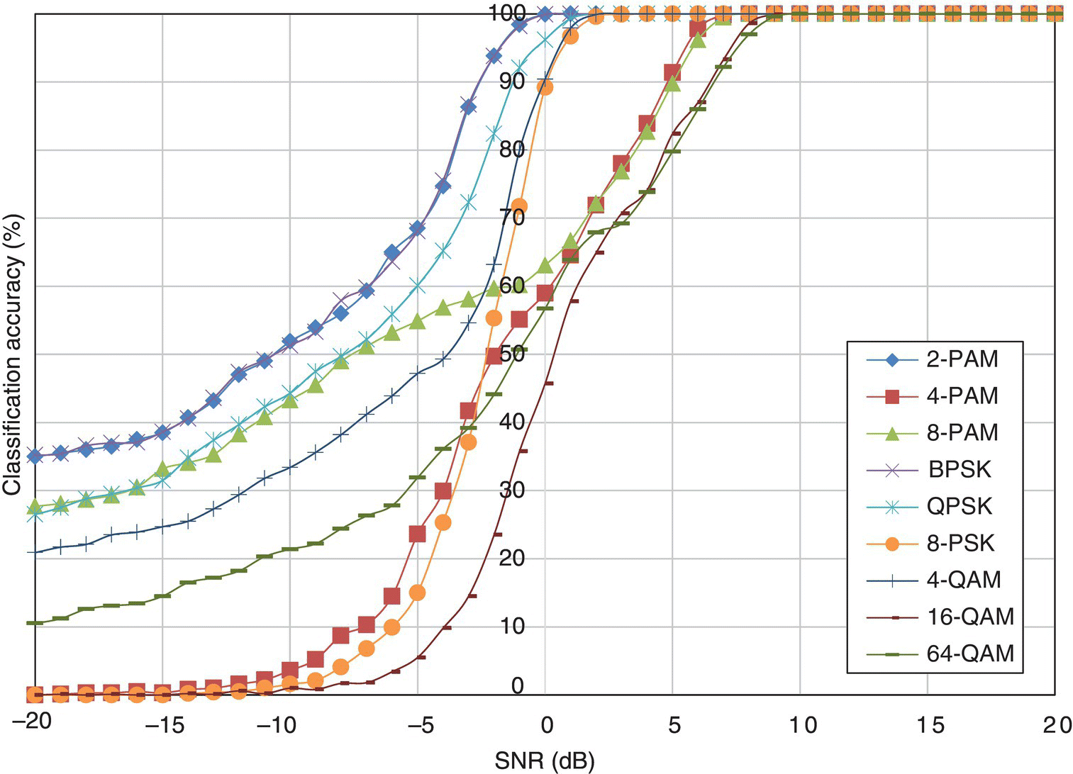
Figure 8.2 Classification accuracy of the ML classifier in AWGN channel.
where Ls is the number of signal realizations that have been successfully classified. It is clear that with lower SNR (higher noise level) there is significant performance degradation for all modulations. Among all the modulations, 2-PAM, BPSK and QPSK have relatively higher classification accuracy at all noise levels. The 8-PSK and 4-QAM are also easier to classify with perfect classification (classification accuracy of 100%) achieved below 5 dB. Meanwhile, 4-PAM, 8-PAM, 16-QAM and 64-QAM require high signal power to achieve perfect classification. It is clear that higher-order modulations are more difficult to classify. Under the same noise level, the modulation symbols of a high-order digital modulation are more densely populated and make the symbol states much less distinctive. It is worth noting that the order of the modulation on a single signal dimension has closer correlation to the classification difficulty. Both having four symbol states, 4-PAM has four states on one dimension while QPSK and 4-QAM have fewer states on each dimension. Therefore, the classification of 4-PAM is more difficult than those for QPSK and 4-QAM. The perfect classification of all modulations by the ML classifier is achieved when the SNR level is higher than 9 dB.
In Figure 8.3, the classification accuracy of the one-sample KS test classifier is listed for each testing signal modulation. Similar behaviour is observed for the one-sample KS test classifier where high-order modulations have lower classification accuracy under the same noise level. Compared with the ML classifier, the performance of the one-sample KS test classifier is inferior but with a small margin. The biggest difference is observed for 8-PSK modulation, where an SNR of 9 dB is required to achieve perfect classification while only 2 dB is need for the ML classifier. The same observation applies to QPSK modulation. The reason for the classification difference for higher-order PSK modulation could be that the one-sample KS test classifier processes the decomposed signal I and Q segments. Therefore, the separation of modulation symbols in their phase is not exploited enough. The perfect classification of all modulations by the one-sample KS test classifier is achieved when the SNR level is higher than 12 dB.
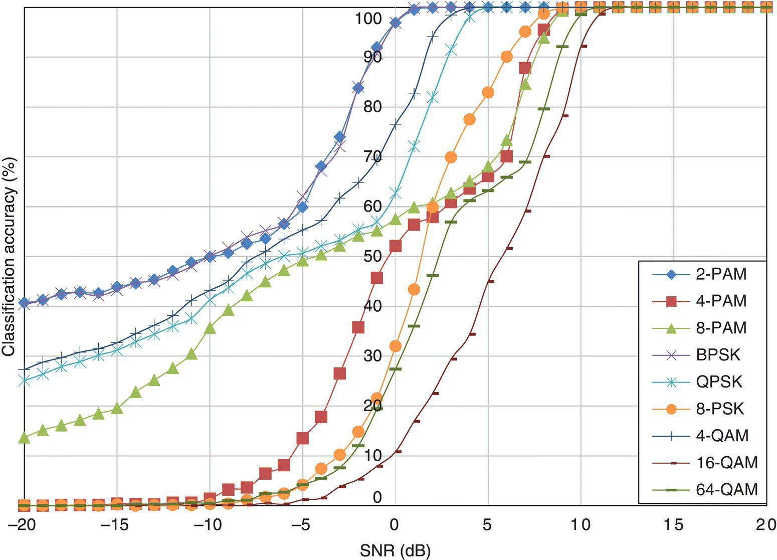
Figure 8.3 Classification accuracy of the KS test classifier in AWGN channel.
In Figure 8.4, the classification accuracy of the KNN classifier using moments is listed for each testing signal modulation. That for the cumulant-based classifier is shown in Figure 8.5. One significant performance difference between the high-order statistics-based classifiers is that their classification accuracy for certain high-order modulations has an upper bound which cannot be exceeded regardless of the noise level. The reason for the upper bound will be explained in the next section when we investigate the effort of signal length on classification accuracy for different classifiers.
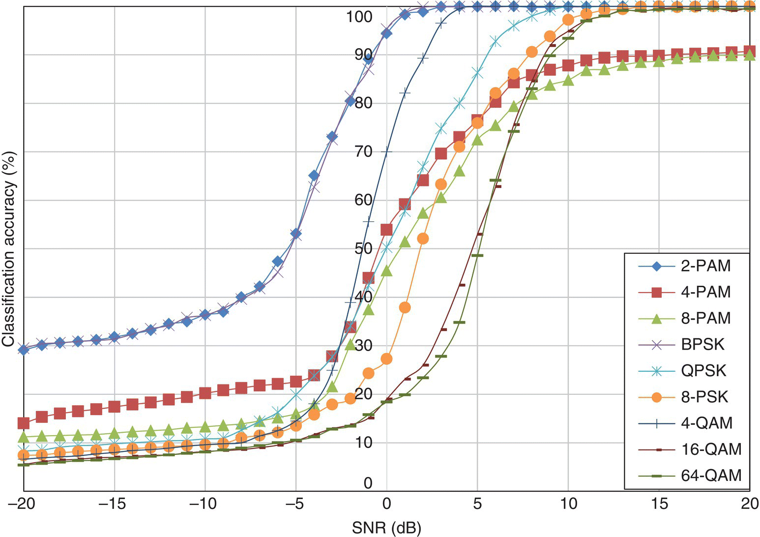
Figure 8.4 Classification accuracy of the moment-based KNN classifier in AWGN channel.
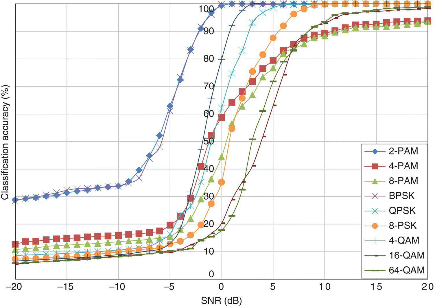
Figure 8.5 Classification accuracy of the cumulant-based KNN classifier in AWGN channel.
Apart from that, the moment-based and cumulant-based KNN classifiers share the same degraded performance for high-order PSK modulation for the same reason as the one-sample KS test classifier. In fact the effect is even more obvious for the high-order statistics feature-based classifiers. The performance profiles of the moment-based and cumulant-based classifiers are very similar, although the cumulant-based KNN classifiers have slightly better accuracy in general.
In Figure 8.6, the classification accuracy of the GP-KNN classifier using moment and cumulant features is listed for each testing signal modulation. Compared with the KNN classifier using the same features but without feature selection and feature combination, the performance profile for the GP-KNN classifier shows that the classification accuracy for some of the higher-order modulations is similar. The reason for the change of performance characteristic is the result of the KNN classification fitness evaluation in the GP process. The fitness evaluation calculates the average classification accuracy of a group of training signals from all modulations. Effectively, it encourages the improvement of average classification accuracy. Therefore, the resulting performance pattern is likely to be restructured.
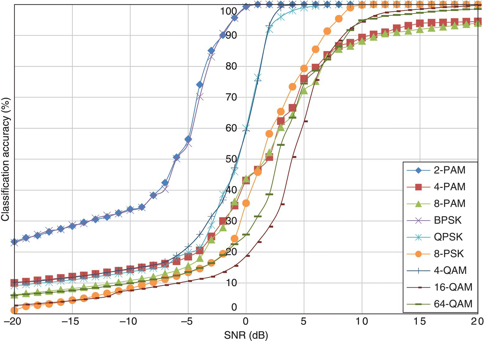
Figure 8.6 Classification accuracy of the GP-KNN classifier in AWGN channel.
In Figure 8.7, the classification accuracy of the EM-ML classifier for different modulations in AWGN channel with varying noise levels is shown. The EM-ML classifier shares some of the performance characteristics of the ML classifier. The optimal classification accuracy in the given noise level range is not limited by the number of samples available for analysis, unlike the moment- and cumulant-based classifiers. However, the high-order modulations have significantly lower classification accuracy as compared with the ML classifier. The difference between the EM-ML classifier and the ML classifier is that, for the ML classifier, a single set of channel parameters is used for the evaluation of likelihood for different hypotheses. Meanwhile, the EM-ML classifier estimates a different set of channel parameters for each modulation hypothesis by using the criteria of maximum likelihood. For false modulation hypotheses, the effect of the EM-ML combination is that the mismatch between the observed signal and the false hypothesis is minimized by the EM estimator. Therefore, classification accuracies for some modulations are reduced.
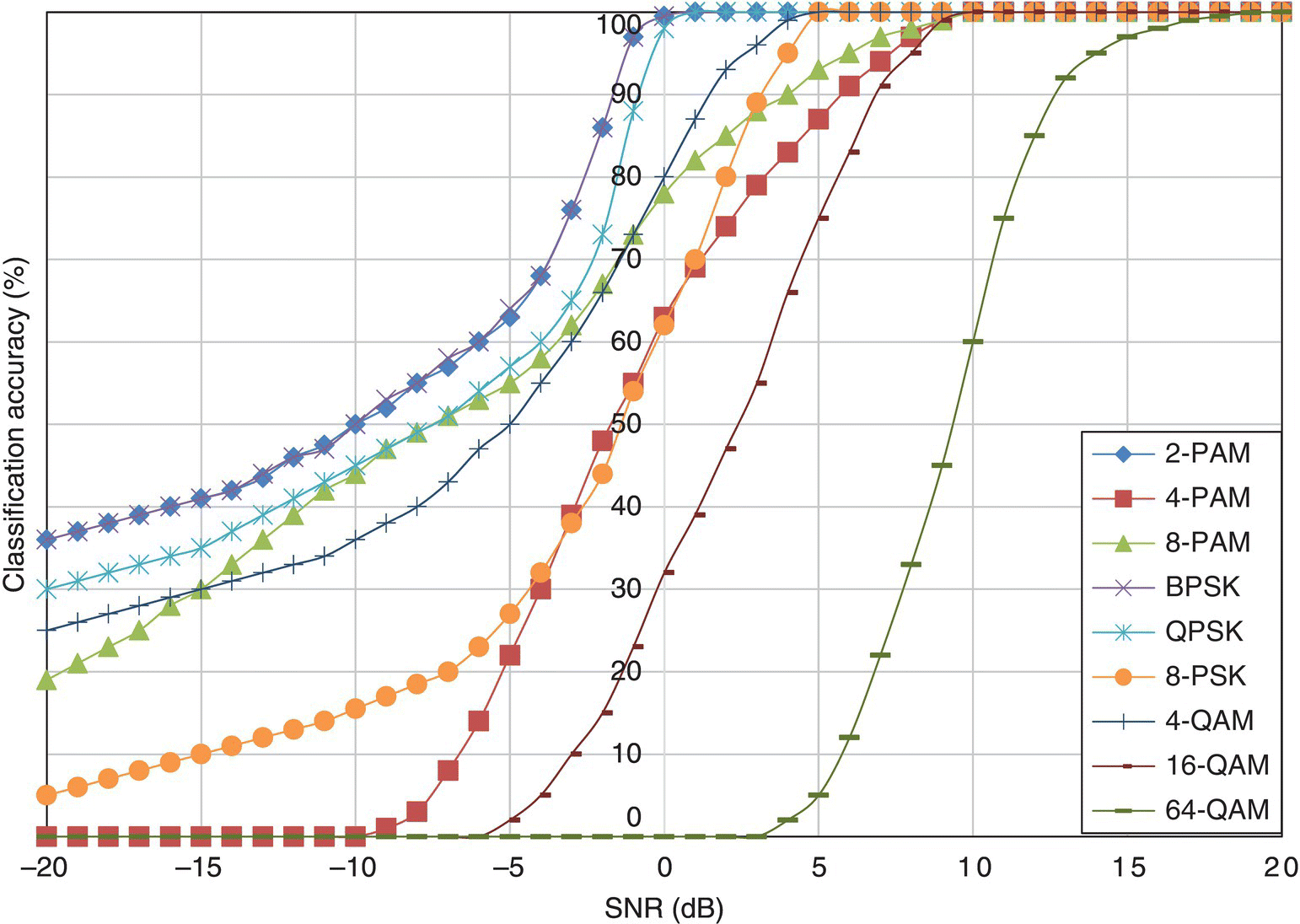
Figure 8.7 Classification accuracy of the EM-ML classifier in AWGN channel.
Taking the average of the classification accuracies of all modulations for each classifier, Figure 8.8 provides an overview of the performance comparison between different classifiers in the AWGN channel. It can be seen that the ML classifier has superior classification accuracy at all noise levels. Despite using the same ML classification decision-making method, the EM-ML classifier has significantly lower classification accuracy. However, it is still superior to most of the other classifiers. The KS test classifier is another classifier that is highly accurate in most noise levels. While being superior to the KS test classifier in some noise levels, the moment- and cumulant-based classifiers suffer at high SNR due their limited ability to process signals of small sample size. The GP-KNN classifier shows a small improvement over the basic KNN classifier using either moment or cumulant features.
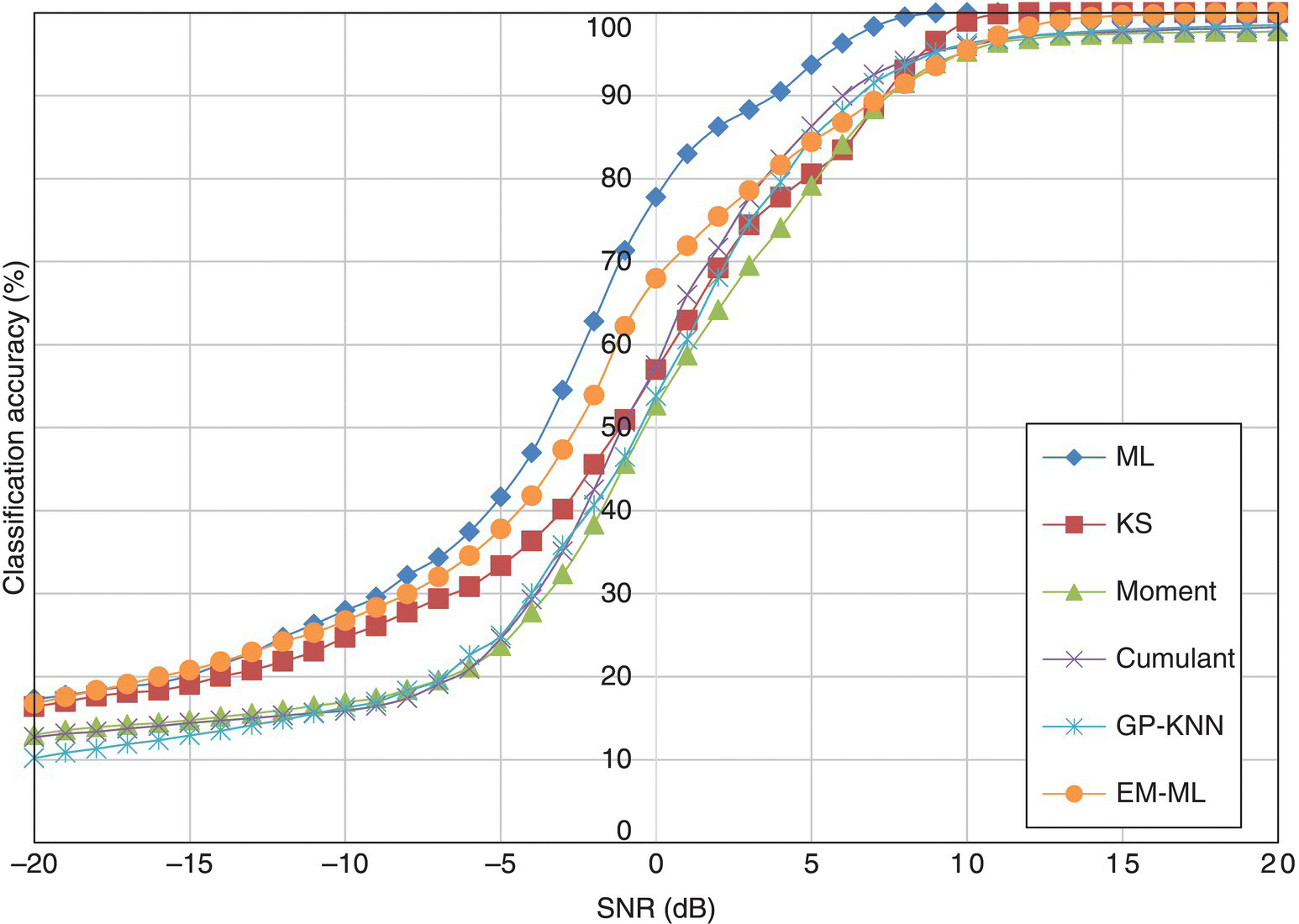
Figure 8.8 Average classification accuracy of all classifiers in AWGN channel.
8.4 Classification Accuracy with Limited Signal Length
One aspect of the robustness of a classifier is how it performs with a limited number of signal samples available for analysis. Performance of a classifier is affected by the number of samples. An example would be the distribution test-based classifier. To construct the empirical distribution, there must be a high enough number of signal samples to calculate the distribution. The more samples there are the more accurately would the empirical distribution resemble the true underlying distribution. When a limited number of signal samples is available, outliners in the signal distribution could create distortion to the modelling of signal distribution. Therefore the classification performance can be affected. In this set of experiments we repeat the experiments in Section 8.3. However, the noise level is fixed at SNR = 10 dB while signals of varying lengths are tested. The signal lengths tested vary from 50 to 1000 with a step of 50.
In Figure 8.9, the classification accuracy of the ML classifier is listed for each testing signal modulation given different signal lengths. Most modulations can be classified with accuracies of over 90% with as few as 50 samples available for analysis. The only exception is 16-QAM and 64-QAM modulations. To guarantee perfect classification of the two modulations over 350 samples are needed. Meanwhile, for the other modulation, 150 samples are enough to achieve the same goal. The reason why 16-QAM and 64-QAM modulation are more difficult to classify given a smaller sample size is that they both have higher number symbol states. Given 50 samples, it is not even enough to cover all the symbol states in the 64-QAM modulation. To ensure high classification accuracy, there need to be enough signal samples from each symbol state. Thus this property of a receiver can be fully represented. When the same number of signal samples is distributed to different symbol states, it is obvious that the higher-order modulations will have few samples for each symbol states.
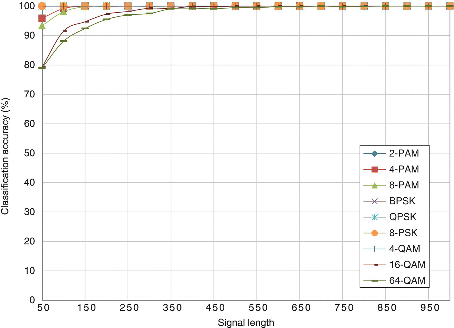
Figure 8.9 Classification accuracy of the ML classifier with different signal length.
In Figure 8.10, the classification accuracy of the KS test classifier is listed for each testing signal modulation given different signal lengths. It is clear that the effect of increased modulation order has a more significant impact on the classification accuracy. Lower-order modulations such 2-PAM, BPSK and QPSK are easily classified with as few as 50 samples. Also, 4-PAM, 8-PAM and 8-PSK have similar performances where a perfect classification is achieved with more than 450 signal samples. Again, the higher-order modulations, that is, 16-QAM and 64-QAM, require a significant number of samples to achieve high classification accuracy. With as few as 1000 samples, neither of the modulations can be perfectly classified.
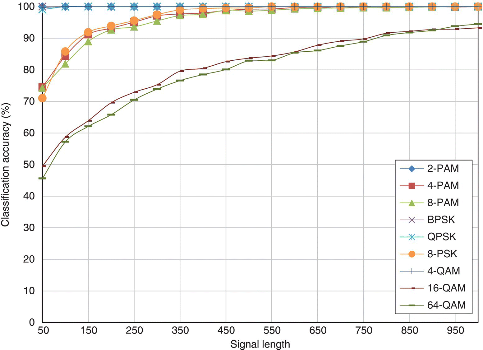
Figure 8.10 Classification accuracy of the KS test classifier with different signal length.
In Figure 8.11, the classification accuracy of the moment-based KNN classifier is listed for each testing signal modulation given different signal lengths. The results for the cumulant-based classifier are given in Figure 8.12. In both cases there are clear performance differences among all the modulations. The lower-order modulations, such as 2-PAM, BPSK and 4-QAM modulations, reach perfect classification when more than 250 samples are available for analysis. Apart from these, QPSK is the only other modulation which can be classified with 100% accuracy when fewer than 1000 samples are given. Among the rest of the modulations, it is interesting that high-order PAM modulations have higher classification accuracy, when fewer than 400 samples are available for analysis. However, the performance improvement with increased sample size is inferior to that found for high-order QAM modulations.
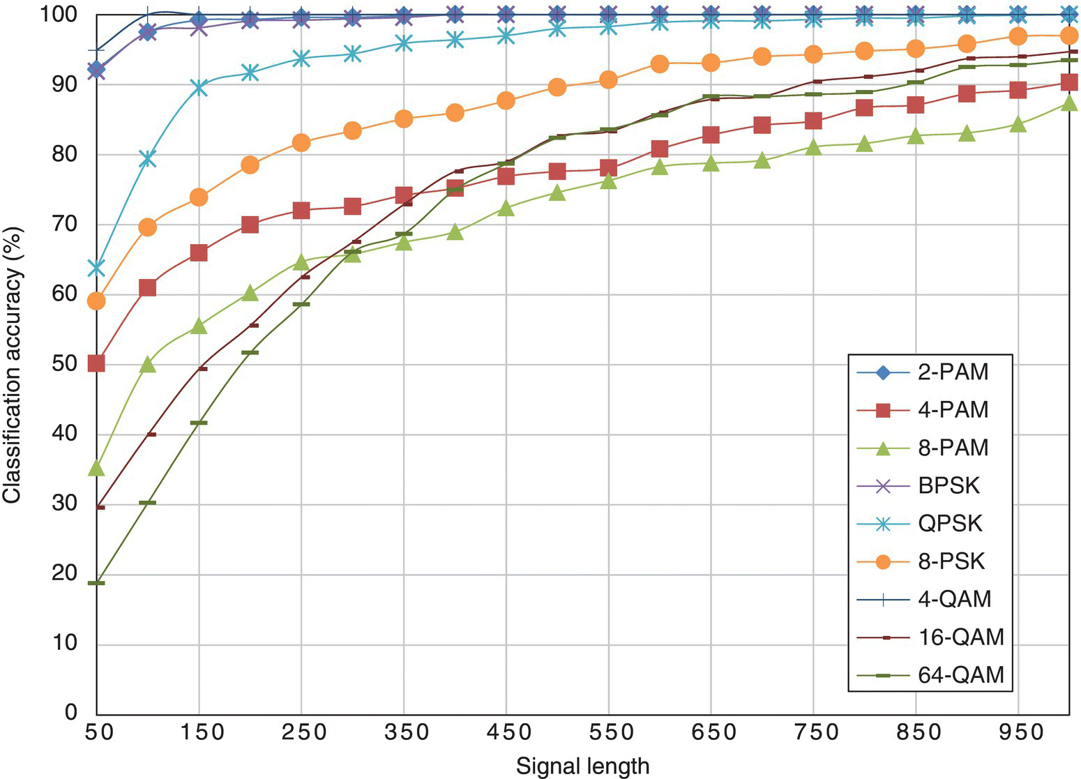
Figure 8.11 Classification accuracy of the moment-based classifier with different signal length.
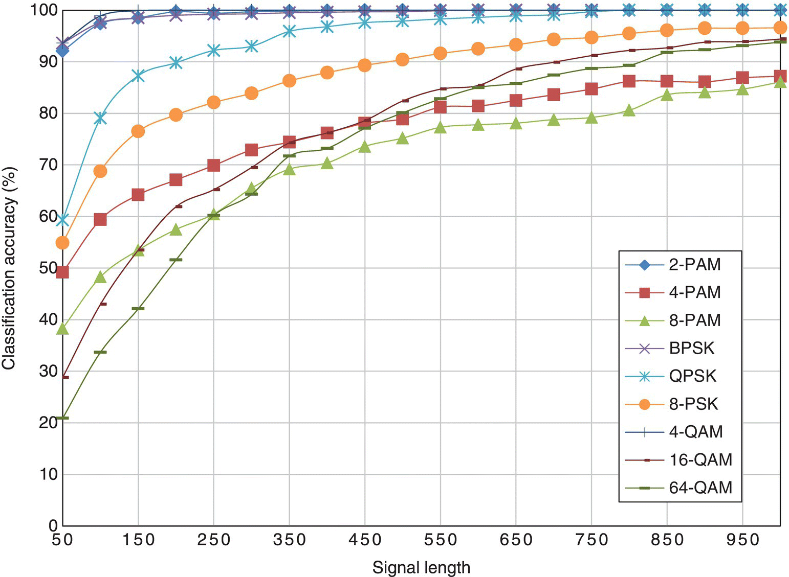
Figure 8.12 Classification accuracy of the cumulant-based classifier with different signal length.
In Figure 8.13, the classification accuracy of the moment- and cumulant-based GP-KNN classifier is listed for each testing signal modulation given different signal lengths. Again, lower-order modulations show better classification accuracy. For 2-PAM, BPSK and 4-QAM, perfect classification is achieved given 150 samples for analysis. The same condition is met when 300 and 550 samples are available for QPSK and 8-PSK respectively. Different from the moment-based and cumulant-based classifiers, the GP-KNN classifier shows a much more similar performance profile for both higher-order PAM and QAM modulations. Yet none of these modulations can be classified perfectly with fewer than 1000 signal samples.
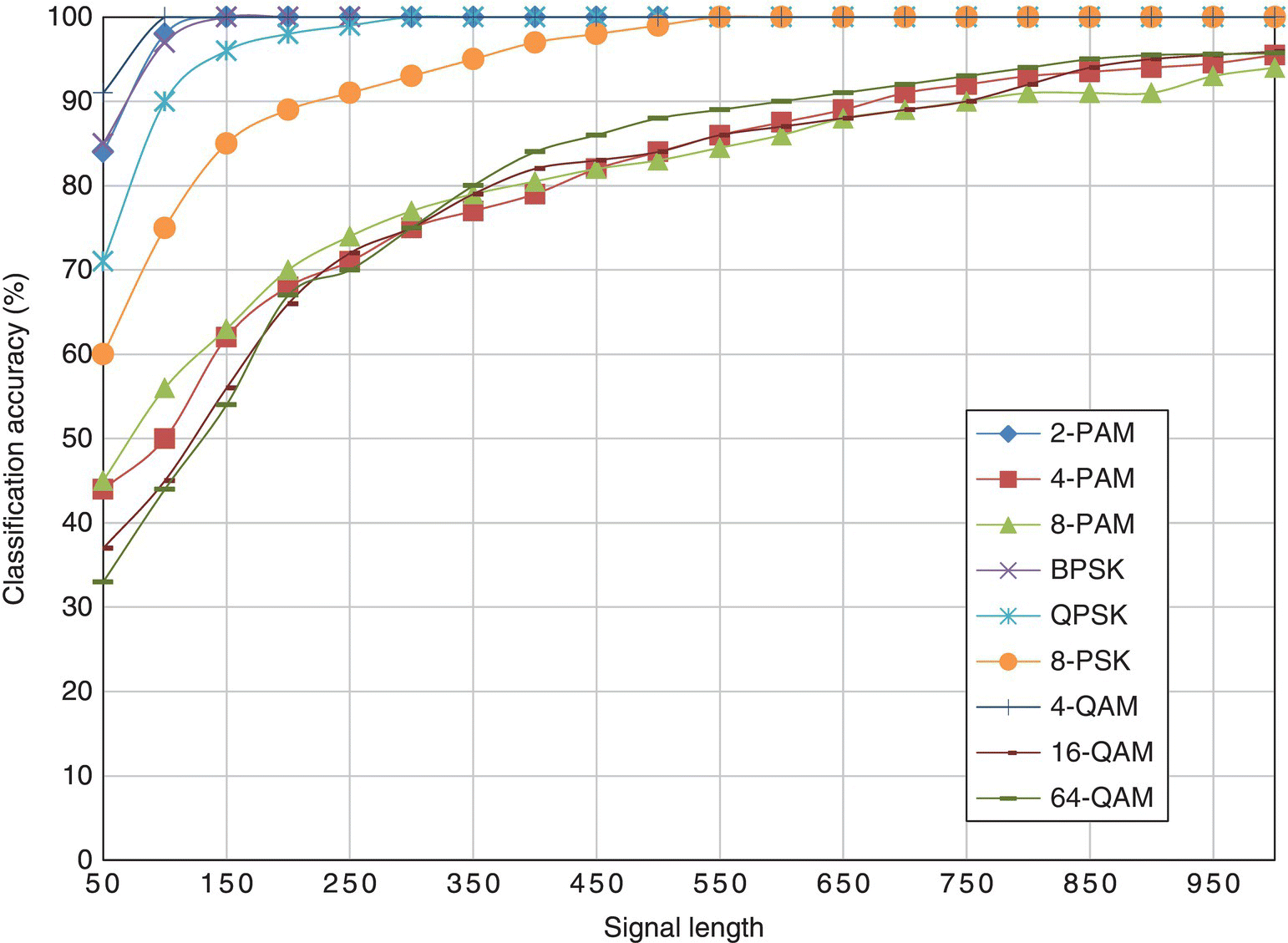
Figure 8.13 Classification accuracy of the GP-KNN classifier with different signal length.
In Figure 8.14, the results from the EM-ML classifier are given. Like the ML classifier, the classifier is robust given a reduced number of samples for most modulations. However, the 64-QAM is more difficult to classify and shows a noticeable degradation with fewer signal samples for analysis.
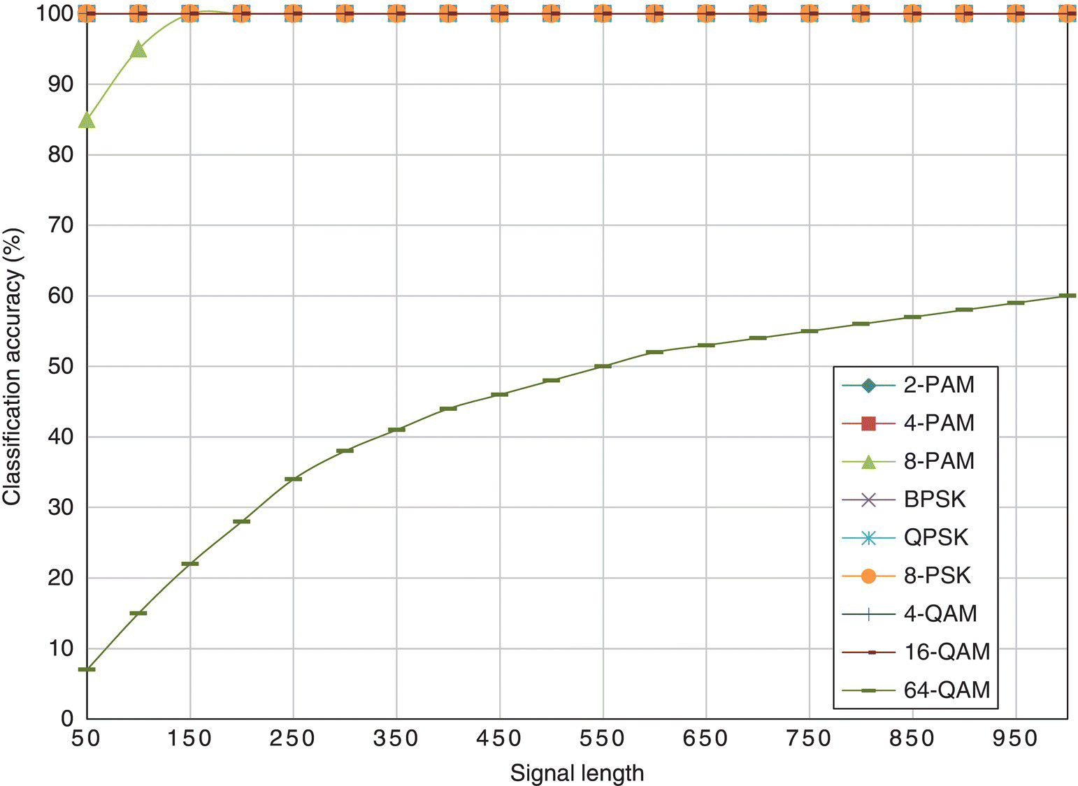
Figure 8.14 Classification accuracy of the EM-ML classifier with different signal length.
Given the average classification accuracy of different classifiers in the fading channel with frequency offset in Figure 8.15, the ML classifier is obviously superior to all the other classifiers. The moment- and cumulant-based classifiers are much limited by the sample size. The limitation is improved when feature selection and combination is performed using GP. The KS test classifier and the EM-ML classifier have similar performance patterns. The EM-ML classifier has higher classification accuracy with a small number of signal samples. On the other end, when more signal samples are available for analysis, the KS test classifier shows better performance.
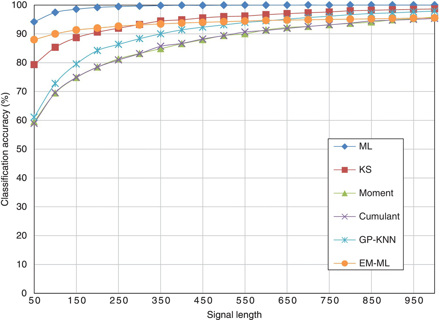
Figure 8.15 Average classification accuracy of all classifiers with different signal length.
8.5 Classification Robustness against Phase Offset
While additive noises are the most commonly considered channel conditions, fading effects are inevitable for systems in wireless channels. To model the fading channel, we use the signal model defined by equation (1.13). In this section we consider only the carrier phase offset. Thus the signal model is given by equation (8.4),
where θo is the phase offset. In this set of experiments, we fix both the noise level and signal length at SNR = 10 dB and 1024, respectively. Phase offsets, ranging from −10° to 10° with a step of 1°, are considered. For each phase offset, 1000 pieces of signal are generated using equation (8.4).
In Figure 8.16, the classification accuracy of the ML classifier is listed for each testing signal modulation against different levels of phase offset. It can be seen that all modulations have 100% classification accuracy when no phase offset is added. Analytically, it is expected that the performance would degrade when an increasing amount of phase offset is introduced. However, this phenomenon is not observed for the majority of the modulations. It could be concluded that this is a result of the robustness of the ML classifier when moderate amounts of the phase offset are introduced. The only modulation affected by the channel condition significantly is the 16-QAM modulation. Performance degradation is experienced when more than 4° of phase offset is simulated. A dramatic decrease in classification is seen when over 7° of phase offset is considered. In a channel with a phase offset of 10°, the corresponding classification accuracy is reduced to 10%.
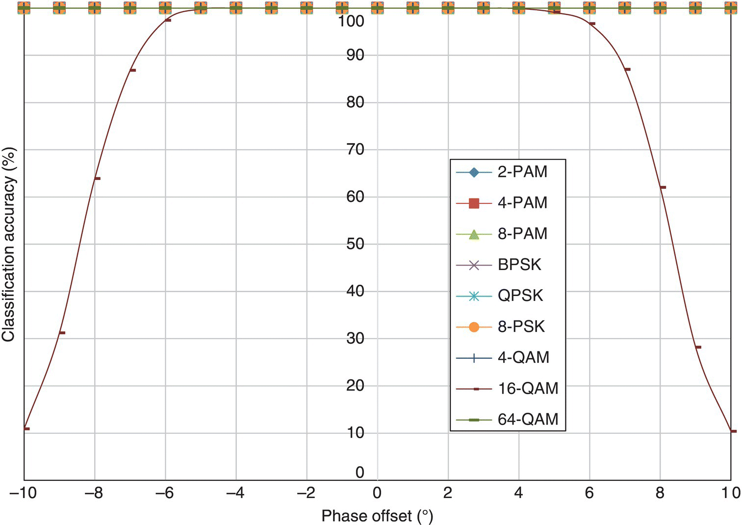
Figure 8.16 Classification accuracy of the ML classifier with phase offset.
In Figure 8.17, the classification accuracy of the KS test classifier is listed for each testing signal modulation against different levels of phase offset. For lower-order modulations, including 2-PAM, 4-PAM, 8-PAM, BPSK, QPSK, 8-PSK and 4-QAM, the KS test classifier is robust enough to provide 100% classification accuracy in the given setup when a phase offset of less than 10° is considered. Similar to the ML classifier, the 16-QAM modulation is significantly affected by the phase offset. Interestingly, the 64-QAM classification accuracy increases with more phase offset. As the KS test measured the mismatch between the empirical distribution and the reference distribution, phase offset increases the mismatch when the accurate modulation is used for reference. In the meantime, the mismatch between the distorted empirical distribution and a reference distribution from a false modulation hypothesis is also enlarged. Since the mismatch against the false hypothesis increases at a faster rate with increasing level of phase offset, it could be understood that the classification accuracy can increase with more phase offset. However, in these experiments, such a phenomenon is only observed for 64-QAM modulation.
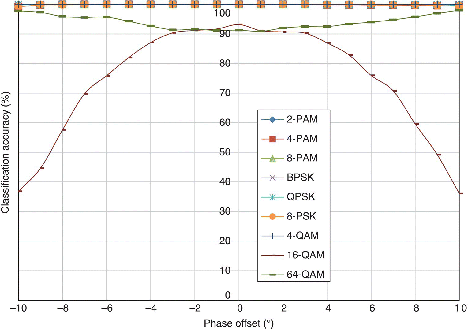
Figure 8.17 Classification accuracy of the KS test classifier with phase offset.
In Figure 8.18, the classification accuracy of the moment-based KNN classifier is listed for each testing signal modulation against different levels of phase offset. The results for the cumulant-based classifier are displayed in Figure 8.19. Between the moment and cumulant features, it is obvious that the cumulant features have higher robustness in the fading channel with phase offset. The biggest difference can be seen for 64-QAM modulation; using cumulants the classifier is able to achieve a constant level of classification accuracy within −10° to 10° of phase offset. Meanwhile, the classification accuracy for 64-QAM sees dramatic degradation when more than 5° of phase offset is introduced. In addition, the robustness of cumulant-based KNN classifier when classifying QPSK is also higher, where severe degradation is only observed when phase offset exceeds 8°.
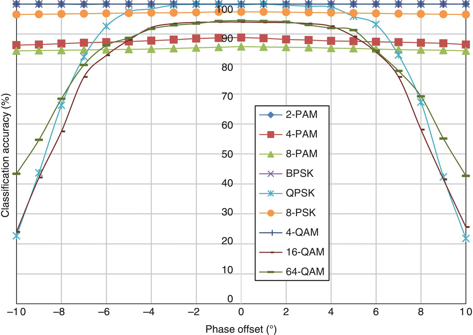
Figure 8.18 Classification accuracy of the moment-based KNN classifier with phase offset.
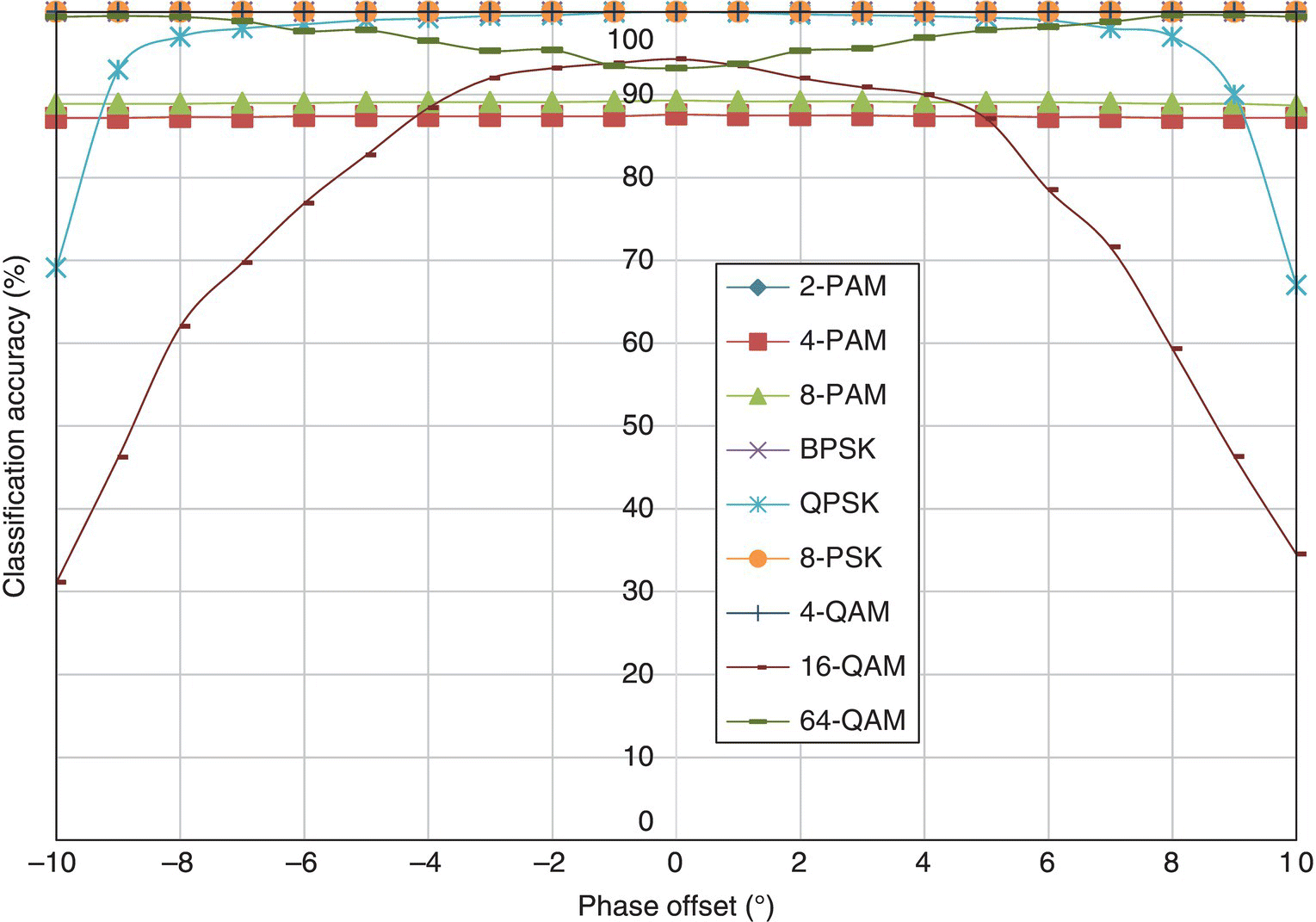
Figure 8.19 Classification accuracy of the cumulant-based KNN classifier with phase offset.
In Figure 8.20, the classification accuracy of the moment- and cumulant-based GP-KNN classifier is listed for each testing signal modulation against different levels of phase offset. Only 2-PAM, 4-QAM and BPSK enjoy consistent classification accuracy. All other modulations experience different degrees of performance degradation when phase offset is introduced. The reason why feature selection and combination does not improve the performance is that the training of the feature selection and feature combination is conducted in a channel without any phase offset. The resulting feature set is inevitably over-trained for the channel without phase offset. When phase offset is introduced, the mismatch between the feature value of a fading signal and the reference signal space is increased.
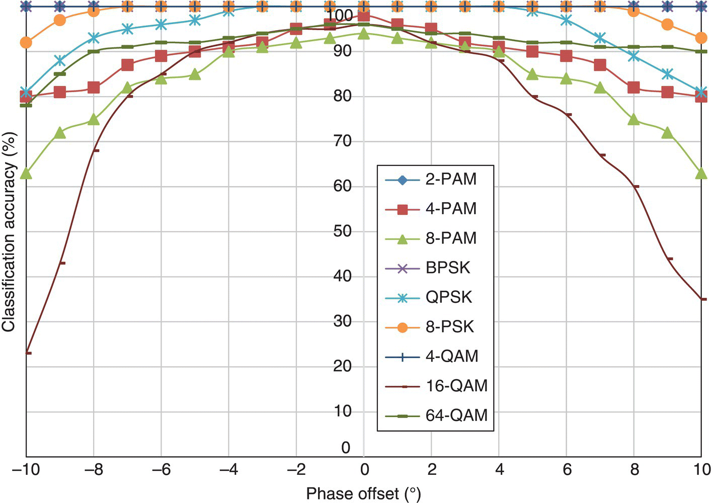
Figure 8.20 Classification accuracy of the GP-KNN classifier with phase offset.
In Figure 8.21, the classification accuracy of the EM-ML classifier is listed for each testing signal modulation against different levels of phase offset. The EM-ML classifier shows excellent performance in the fading channel with phase offset. For all modulations, there is no obvious performance degradation. Since the estimation of channel coefficient consists of the estimation of carrier phase offset, the phase offset is effectively compensated in the ML classification stage. Thus, the EM-ML classifier has very robust performance in the fading channel with some phase offset.
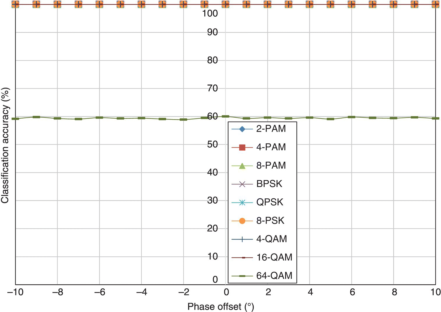
Figure 8.21 Classification accuracy of the EM-ML classifier with phase offset.
To conclude this section, we give the average classification accuracy over all modulations for each classifier in the case of a fading channel with carrier phase offset in Figure 8.22. Between −8° and 8° of phase offset, the ML classifier is still the best classifier in terms of its classification accuracy. However, beyond 8°, the EM-ML classifier has higher classification accuracy thanks to its inherent ability to compensate the phase offset estimated in the EM stage. The weakest classifier in the fading channel is the moment-based KNN classifier. Its performance degradation with an increasing amount of phase offset is most severe among all the classifiers.
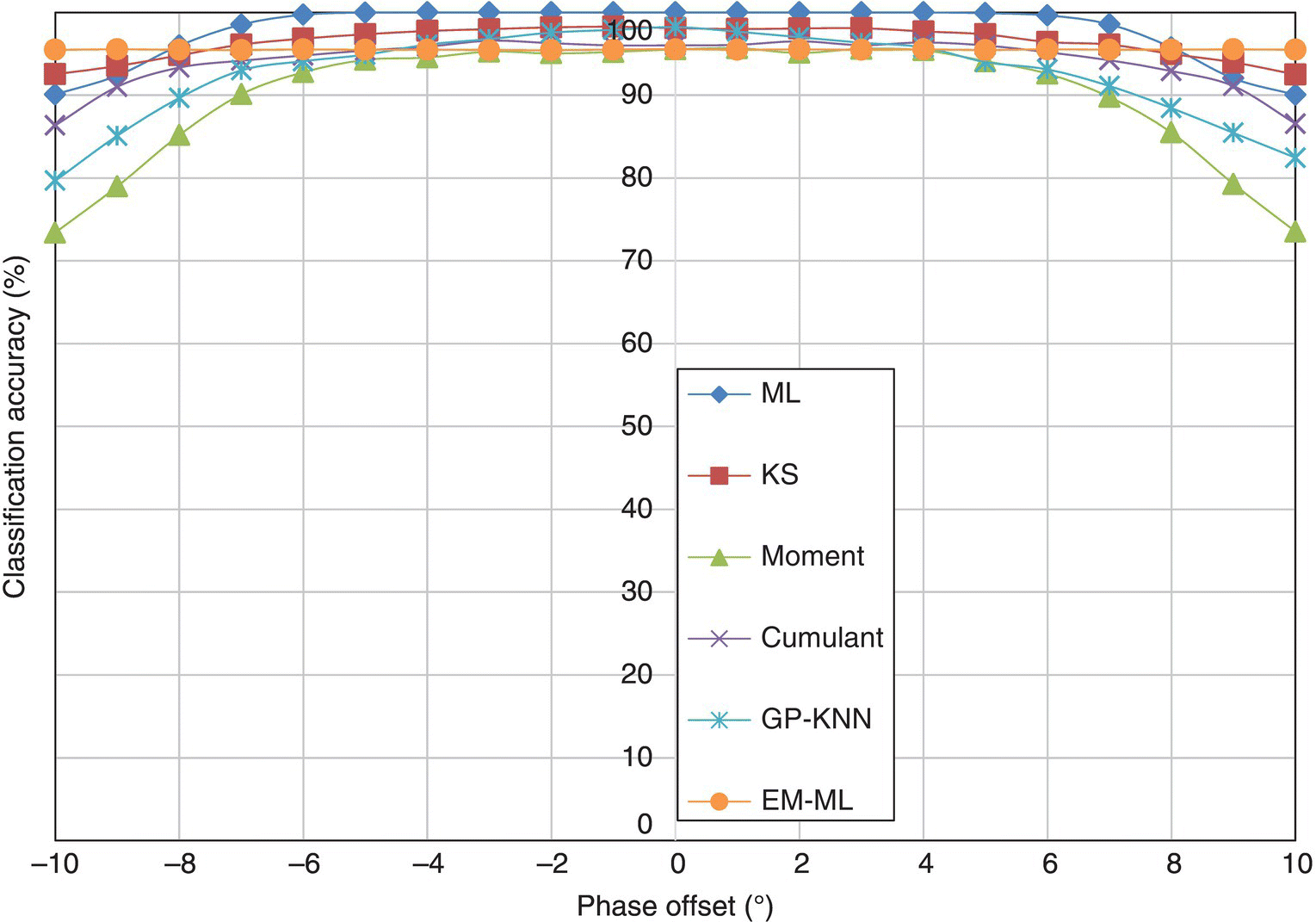
Figure 8.22 Average classification accuracy of all classifiers with phase offset.
8.6 Classification Robustness against Frequency Offset
Another practical channel effect to be considered in common fading channels is carrier frequency offset. To model the received signal in a fading channel with frequency offset, we derive the following equation (8.5) from equation (1.13). Here,
fo is the frequency offset. It is worth noting that, in the simulation, a relative frequency fo/f, which is calculated from the ratio between the actual frequency offset and the symbol sampling frequency, is used to indicate different levels of frequency offset. The experiment setup in this section is the same as in the previous section, the only difference being that phase offset is neglected and frequency offset is considered. The range of frequency offset used in the simulation is from 1 × 10⁻⁵ to 2 × 10⁻⁴.
In Figure 8.23, the classification accuracy of the ML classifier for different modulations with varying levels of frequency offset is given. Different from the other channel conditions we have investigated, the effect of frequency offset is more impulsive in terms of the classification accuracies for different modulations. Most modulations see a dramatic decrease in classification accuracy when a small amount of frequency is added. Surprisingly, high-order modulations, namely 8-PSK and 64-QAM, have much superior classification accuracy when considering frequency offset. This significantly biased performance profile is caused by the unique effect of frequency offset on lower-order modulations. Unlike the phase shift in fading channel, frequency offset introduces a phase shift which is time variant and incremental over time. Therefore, the resulting effect is no longer a shift of the entire signal constellation. Instead, it produces a rotational dispersion of the signal samples. For modulations of lower order, the effective result of frequency offset is the increase in symbols numbers when perceived by the receiver. Therefore, the classification is biased for higher-order modulations. It is not unique to 8-PSK or 64-QAM. If other higher-order modulations are included in the modulation pool, it is likely that they will be correctly classified more often than are 8-PSK or 64-QAM.
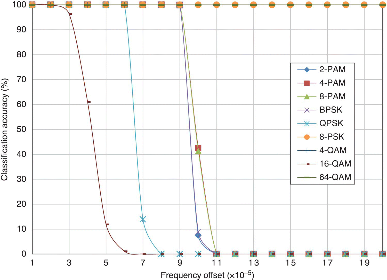
Figure 8.23 Classification accuracy of the ML classifier with frequency offset.
In Figure 8.24, the classification accuracy of the KS test classifier for different modulations with varying level of frequency offset is shown. The observation of the results coincides with what has been discussed previously for the ML classifier. In fact, this could be said for the remainder of the benchmarking classifiers. The results for the moment-based KNN classifier, the cumulant-based KNN classifier, the moment- and cumulant-based GP-KNN classier and the EM-ML classifier are shown in Figures 8.25–8.28, respectively.
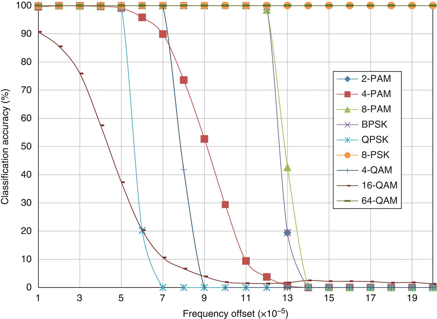
Figure 8.24 Classification accuracy of the KS test classifier with frequency offset.
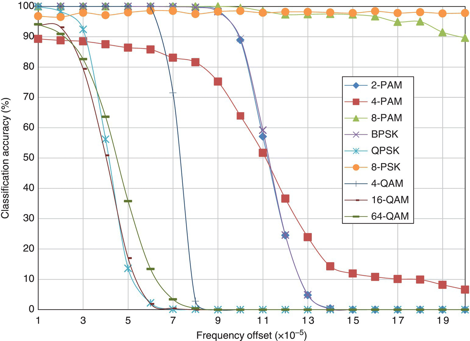
Figure 8.25 Classification accuracy of the moment-based KNN classifier with frequency offset.
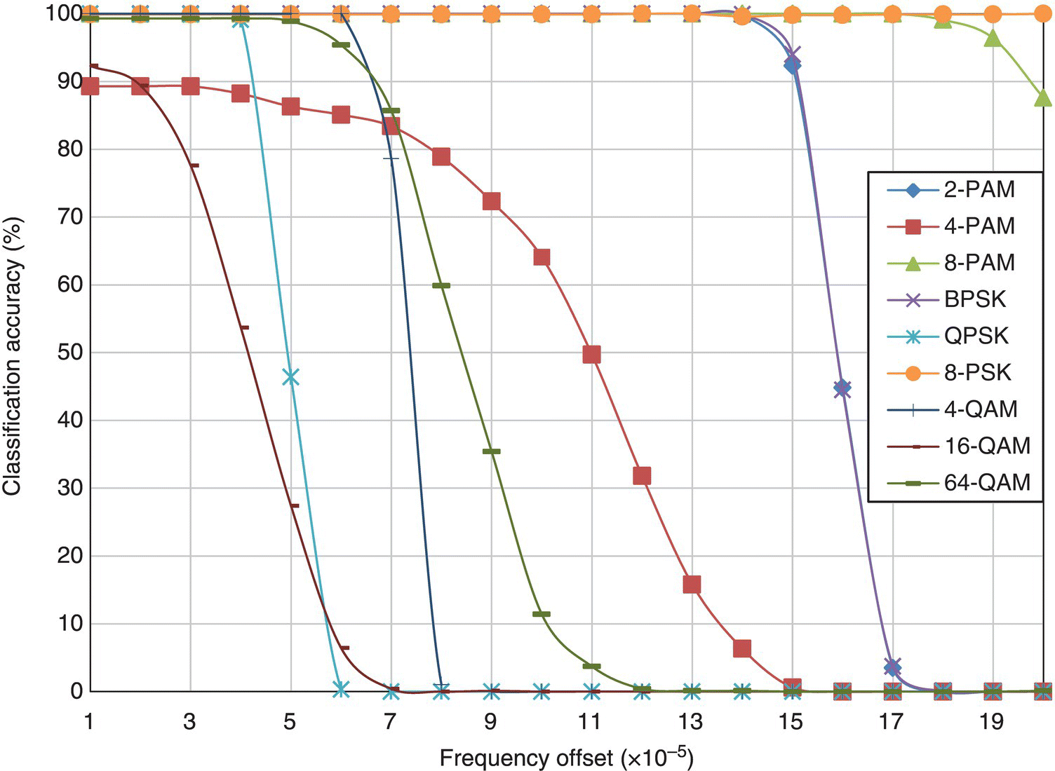
Figure 8.26 Classification accuracy of the cumulant-based KNN classifier with frequency offset.
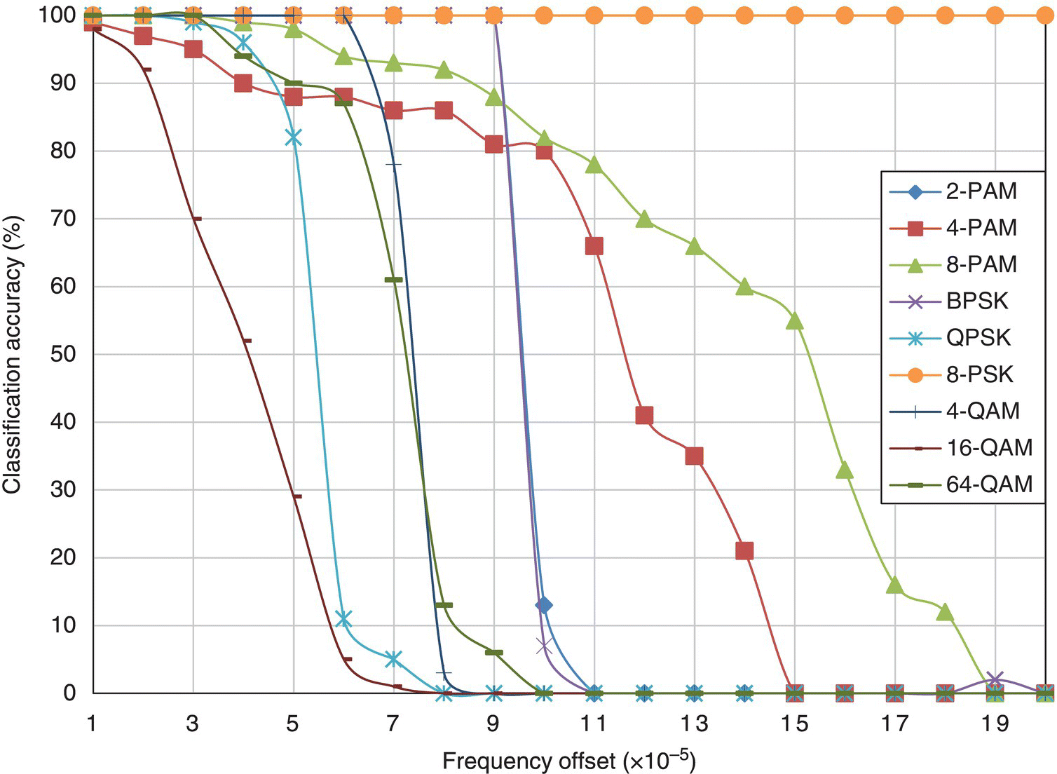
Figure 8.27 Classification accuracy of the GP-KNN classifier with frequency offset.
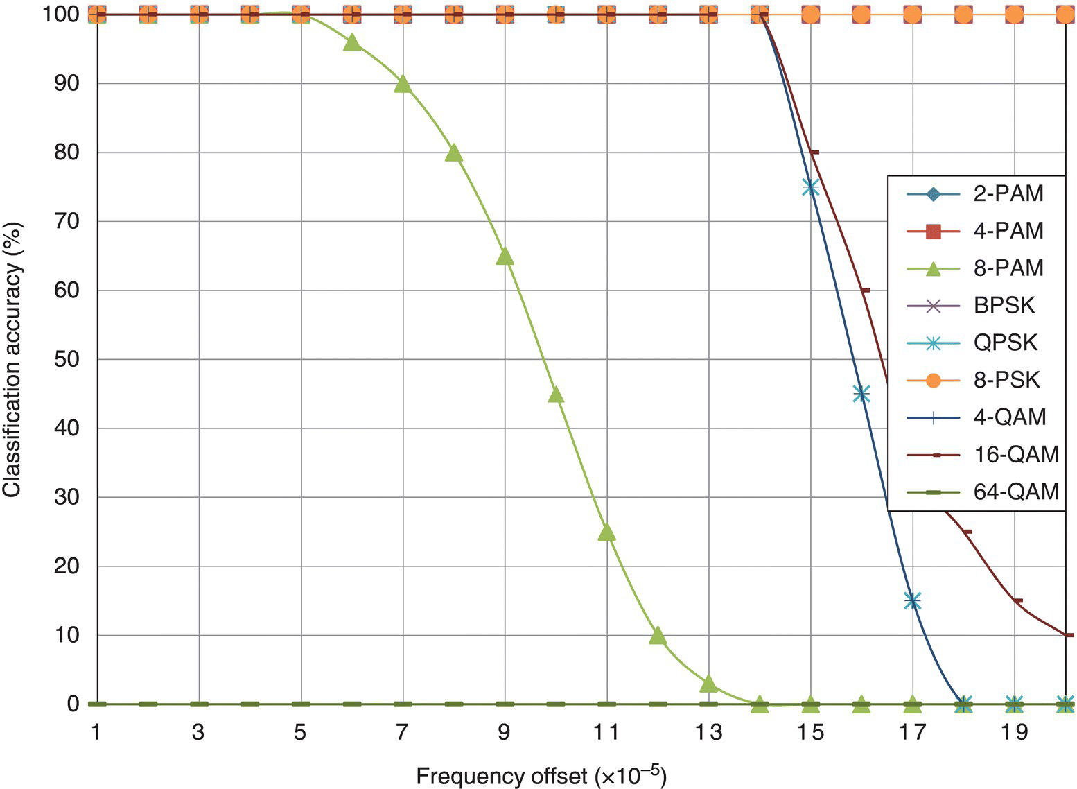
Figure 8.28 Classification accuracy of the EM-ML classifier with frequency offset.
Figure 8.29 shows the average classification accuracy of each classifier in the simulated fading channel with carrier frequency offset. Owing to the severe distortions caused by frequency offsets, most classifiers have a rather distorted performance profile. However, the trends of the performance changes are shared among most classifiers. The only exception is the EM-ML classifier, while being less accurate when a small amount of frequency offset is added, it is noticeably more robust when a higher level of frequency offset is considered. When most classifiers start to degrade with a frequency offset of 3 × 10⁻⁵, the EM-ML is able to sustain a consistent level of classification accuracy until more than 1.4 × 10⁻⁴ frequency offset is considered.
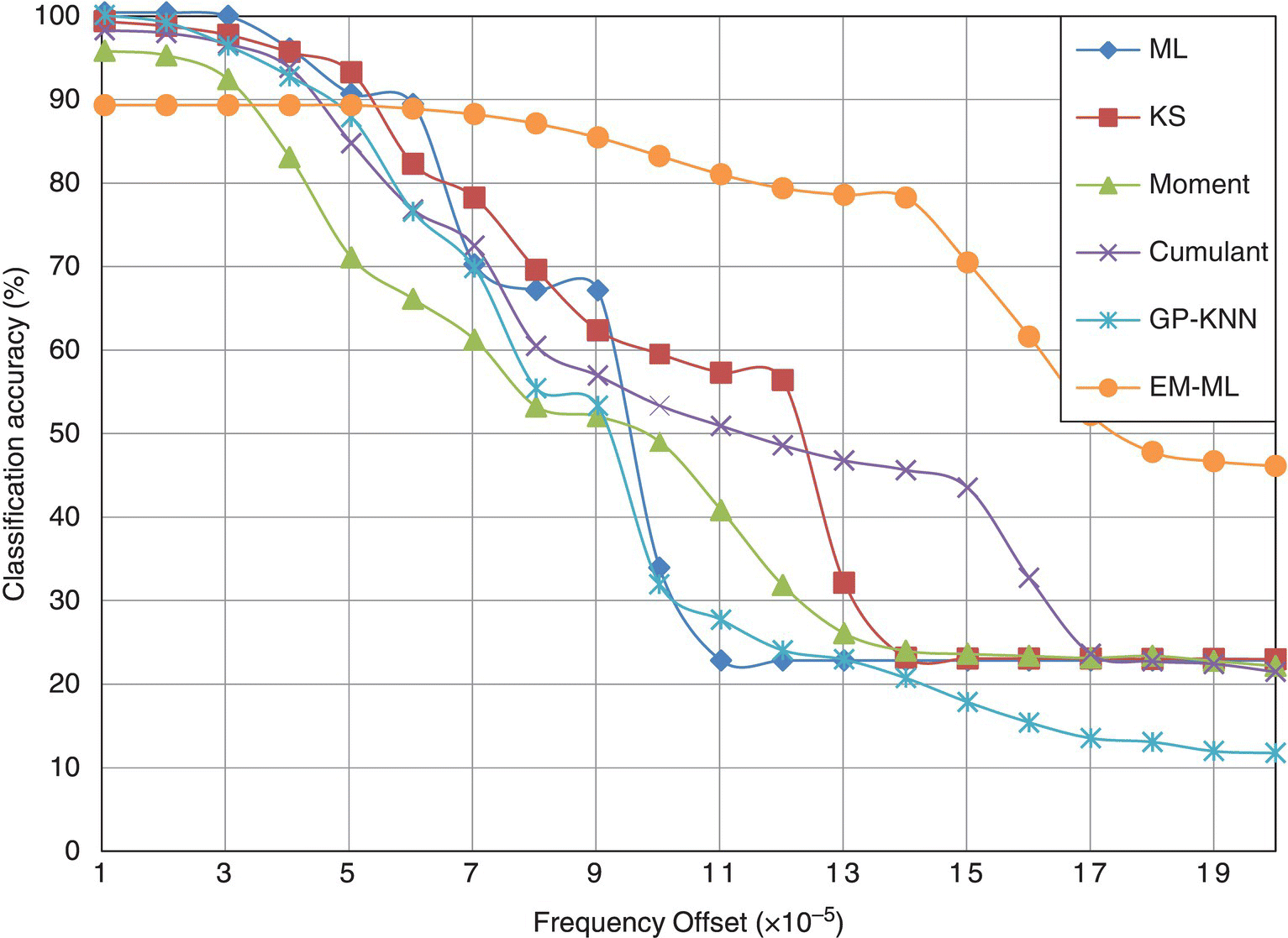
Figure 8.29 Average classification accuracy of each classifier with frequency offset.
8.7 Computational Complexity
The computational complexity of a modulation classifier affects the overall performance of a system in three different ways. First, a complex classifier requires a more powerful processing unit in order to obtain an AMC decision. It imposes a string of limitations on the hardware design. Power supply, cooling system, device form factor, cost, compatibility of other units will all be affected. Secondly, a complex classifier requires more time to process each signal frame. For some applications, classification accuracy is the priority and the processing time could be compromised. However, for some time-critical applications, classifiers with low computational complexity are favoured. Thirdly, a complex classifier requires more power to complete an AMC task. This is especially so for mobile communication units where batteries are used to power the processing units. Clearly, a classifier with lower computational complexity with good accuracy is much desired.
From Chapters 3–7 we presented the implementation of many modulation classifiers. It should give an impression of the complexity of each classifier based on these materials. To provide a clear overview of how these classifiers compare with each other in terms of computational complexity we produced Table 8.6, detailing the number of mathematical operations needed to complete the classification of one piece of signal. To enable the calculation of the operation numbers, we make the following assumptions: (i) the modulation candidate pool has I number of modulation candidates, (ii) the number of symbols of the ith candidate modulation is given by Mi, (iii) for each signal realization there are N number of signal samples available for analysis, (iv) the number of reference samples for KNN and GP-KNN classifier is given by L, (v) the GP-evolved feature combination contains G numbers of each operator under a general assumption, and (vi) the EM estimation stage is repeated for K iterations for the EM-ML classifier.
Table 8.6 Number of different operations needed for each classifier
| Addition | Multiplication | Exponentiation | Logarithm | |
| ML |

|

|

|
NI |
| KS test | 2N(log2N + 2I) | 0 | 0 | 0 |
| Moments | 10LN + 10N | 37LN + 37N | 0 | 0 |
| Cumulants | 10LN + 10N + 20L | 37LN + 37N + 44L | 0 | 0 |
| GP-KNN | 10LN + 10N + 20L + LG + G | 37LN + 37N + 44L + LG + G | LG + G | LG + G |
| EM-ML |

|

|

|
KNI |
For the ML classifier, the evaluation of the likelihood for each modulation hypothesis is the most costly process in terms of computation. All the operations are involved in the likelihood. Moreover, they are repeated for each modulation hypothesis, each modulation state and each signal sample. For the EM-ML classifier, the process is then again repeated for a certain number of iterations. Consequently, the computational complexity of the EM-ML classifier is the highest. For the moment- and cumulant-based features, the calculations involve only multiplication and addition. Therefore they are relatively simple. When employing GP for feature selection and combination, the initial investment in the training stage is rather expensive. However, it should be pointed out that once the features are selected and combined, the training step does not need to be repeated for each testing signal realization. In the testing stage, the GP-KNN classifier has a slightly higher computational complexity than does the basic KNN classifier using the same features. The one-sample KS test classifier is known to have lower computational complexity. The construction of the empirical distribution requires only multiplication. However, the requirement of reference theoretical CDF values requires additional calculation. If the reference values are prepared, extra space are needed from the system memory to store all these values.
8.8 Conclusion
In this chapter, we analyzed all the classifiers from Chapters 3–7 in terms of their versatility in different system configurations. It is clear that the requirement for channel parameters varies among most classifiers. The best classifier that is able to classify most digital modulations while not needing much prior knowledge of the communication system is the EM-ML classifier. The more important factor of classification accuracy is investigated in Sections 8.3–8.6. Channel conditions including AWGN noise, phase offset, and frequency offset, as well as the limitation of reduced signal sample size, are simulated to test the performance of the ML classifier, the KS test classifier, the moment- and cumulant-based classifiers, the GP-KNN classifier and the EM-ML classifier. Given a matching model, the ML classifier significantly outperforms the rest of the classifiers, when AWGN noise is considered. It also shows higher robustness given a limited number of samples for analysis. However, in complex channels with phase offset and frequency offset, all classifiers experience significant degradation in their classification performance, with the exception of the EM-ML classifier. Thanks to its estimation stage, the phase offset can be completely compensated by the estimation channel coefficient. While not being estimated and compensated, frequency offset also has less impact for the EM-ML classifier. While being versatile and robust, the disadvantage of the ML and EM-ML classifiers is exposed in Section 8.7, where the computation complexity is evaluated for each classifier. The likelihood-based classifiers all require a high number of exponentiation and logarithms, while these operations are not need by the other classifiers. The classifiers with the least amount of computation requirement are the distribution test-based classifiers, which require no exponentiation or logarithm operations and need a lower number of additions or multiplications.
References
- Swami, A. and Sadler, B.M. (2000) Hierarchical digital modulation classification using cumulants. IEEE Transactions on Communications, 48 (3), 416–429.
- Wang, F. and Wang, X. (2010) Fast and robust modulation classification via Kolmogorov–Smirnov test. IEEE Transactions on Communications, 58 (8), 2324–2332.
- Wei, W. and Mendel, J.M. (2000) Maximum-likelihood classification for digital amplitude-phase modulations. IEEE Transactions on Communications, 48 (2), 189–193.
