5.2 Wireless Backhaul Technology
Wireless in transport has long been synonymous with microwave point-to-point (PtP) radio link. For decades microwave radios (MWR) have been used in all levels of transport networks, for short and long hauls. In the digital era main data structures have been PDH and SDH, today it is Ethernet. The majority of MW radios use frequency bands allocated for fixed services between 2 ... 15 GHz, while newer urban installations use frequency bands 18...38 GHz. Typical capacities used to be 2...16 × 2 Mbit/s in access section and 140 Mbit/s, STM-1 or even STM-4 in national trunk lines. The backbone network installations used to be huge in size: long and stabile masts, large parabolic dish antennas, heavy radio and baseband rack installation in air-conditioned special premises.
In the upper level of (core) networks the radios are yielding to optical fiber transmission due to a huge increase of transmission rates. Wireless transport systems, however, have their benefits and are widely used in the access part of the mobile backhaul networks. Mobile and fixed network convergence is reality and this is true also in mobile backhaul.
Over 55% of all MBH physical connections worldwide are on microwave, and a total of 64% of MBH equipment revenue in 2010 was from TDM, dual TDM/Ethernet and packet microwave (Chapter 02). Due to increasing mobile data rates in LTE/LTE-A era the mobile hand-sets' distance to the BTS (eNB) will shorten. Much more capacity is needed per square-kilometer, especially in urban areas. High transport capacities are transmitted to the buildings and cabinets by optical fiber but it is not feasible to wire every small base-station. The capacity of microwave radio technology is increasing to 1 Gbit/s level while new millimeter wave bands offer wider bandwidths and opportunity up to 10 Gbit/s capacities and very dense radio networks.
5.2.1 Radio Wave Propagation
In wireless transport connections radio waves may face several anomalies that must be considered and requires planning. Issues related to radio wave propagation are:
- attenuation due to free path loss, i.e. due to distance;
- attenuation due to atmospheric gases;
- diffraction fading due to obstruction of the path obstacles;
- fading due to atmospheric multipath or beam defocusing;
- fading due to multipath from ground and other surface reflections;
- attenuation due to precipitation (weather) or solid particles in the atmosphere;
- variation of the angle-of-arrival at the receiver terminal and angle-of-launch at the transmitter terminal due to refraction;
- reduction in cross-polarization discrimination (XPD) in multipath or precipitation conditions;
- signal distortion due to frequency selective fading and delay during multipath propagation.
When radio wave propagates from transmitter to receiver its intensity decreases. Signal attenuation as a function of distance in line-of-sight link is called free space path loss (FSL) and it can be calculated from Equation (5.1).
Unit of f is MHz and d is km. One can see that when distance increases a decade (10-times) signal weakens 20 dB. In multipath non-LOS or near-LOS cases with wider than pencil beam antennas degradation is typically 35-40 dB per decade.
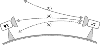
Figure 5.5 Microwave bending (de-focusing) due to changes in atmospheric refraction, a) normal atmosphere, b) sub-refractive, c) super-refractive.
Radio link between two ends is not actually just a line but the radio-frequency power propagated in an area (ellipsoid) defined by Fresnel-zone (Figure 5.6(a)). Link design must be done so that approximately half of the Fresnel zone radius remains clear from obstacles in normal conditions. In lower frequencies and longer hops some margin is needed for the change in atmospheric refraction (b).
Figure 5.6 MW radio hop with Fresnel zone. a) obstacle at distance d1,d2 limits clearance c and causes diffraction attenuation. b) sub-refraction in atmosphere makes obstacle to bulge to the line-of-sight.

Radius of Fresnell zone in distance d1,d2 can be calculated from Equation (5.2).
Radius r is in meters, distances d in kilometers and frequency Gigahertz. If there is an obstacle inside the zone the additional attenuation can be estimated from Equation (5.3):
A single relatively short obstacle reaching the line-of-sight causes 10 dB additional attenuation. Radio wave bending, de-focusing and diffraction attenuation are the main causes of signal degradation and outages in lower MW frequencies and over long hops (Figure 5.5).
Multi-path propagation causes selective fading that varies when atmospheric conditions change. Selective fading distorts the signal and can only be cured by proper radio modem techniques and link hop design that avoids multipath reflections. Calculation methods for radio hop parameters as well as for estimated outage times to dimension radio hops are available in [24].
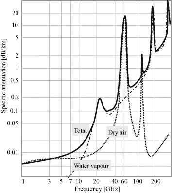
Radio wave is attenuated by gases and water vapor in atmosphere, see Figure 5.7. Water attenuation is negligible below 10...15 GHz and reaches local maximum at 22 GHz where the first water molecules emission peak is. Gas attenuation is moderate in lower MW bands and peaks at 60 GHz where the oxygen attenuation is about 15 dB/km. Gas attenuation is constant and varies slightly when water vapor content changes.
Figure 5.7 Specific attenuation due to atmospheric gases. [ITU-R P.676-8]
Radio signal is also attenuated by rain that is a varying statistical phenomenon. Rain attenuation below about 10 GHz is negligible, but at higher frequencies and over short hops rain is the main cause of outages. Recommendation ITU-R P.837-4 contains maps of rain fall rates (mm/h) exceeded 0.01% of time (53 minutes per year or 4 minutes per month) for different geographical areas. Figures can be scaled for other percentages, too. Once we know the attenuation caused by certain rain-intensity as a function of frequency the needed flat fade margin can be calculated. The margin is taken to link budget tool to optimize radio hop length, antenna sizes, transmit power and other parameters.
Typical rain rates for 99.99% availability range from continental Europe 40 mm/h to Far East 100 mm/h. Radio link is to be dimensioned to withstand this high additional attenuation. Also other time-percentages can be calculated if lower or higher availability is required.
The effects of slow flat fading and faster frequency-selective fading must both be taken into account in link design. There are a number of techniques available for alleviating these effects, most of which alleviate both at the same time. The same techniques often alleviate the reductions in cross-polarization discrimination also. They can be categorized as techniques that do not require diversity reception or transmission, and techniques that do require diversity. It is desirable for economic reasons to avoid diversity whenever possible.
In order to reduce the effects of multipath fading without diversity there are several techniques that can be employed:
- increase of path inclination;
- reduction of effect of surface reflections;
- shielding of the reflection point;
- moving of reflection point to poorer reflecting surface;
- optimum choice of antenna heights;
- choice of vertical polarization;
- use of antenna discrimination;
- reduction of path clearance.
There are also installation related impairments like antenna misalignment, mast or pole vibration, RF cable and connector attenuation. Wet snow accumulating on antenna radom also cause attenuation in higher MW bands.
5.2.2 Frequencies and Capacities
Microwave radio transmits in a selected frequency band and occupies a bandwidth at that frequency. Both frequency band and bandwidth are technical design parameters, but also local spectrum regulation has an effect on frequency usability and (license) cost.
Figure 5.8 Radio data rate as a function modulation with different radio channel bandwidths.
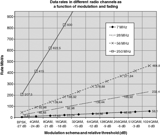
Figure 5.8 shows achievable data rates as a function of modulation used. Data rate is the higher the wider signal bandwidth and the more bits per transmitted symbol (i.e. the higher the modulation schema). More advanced modulation requires a stronger signal and is also more prone to interference. BPSK is a robust modulation using only two signal levels. 1024QAM is a highly advanced modulation method only recently introduced in MW radios. Decibels show how much signal can attenuate to achieve the same quality as with 1024QAM. So, 64QAM requires roughly 12 dB stronger signal than QPSK (4QAM).
Channel widths 7...28 MHz are widely available for major MW bands globally. The number of 56 MHz channels is quite limited and they may already have been allocated for prevailing operators. 250 MHz channels are available in the newest high capacity bands at 40...90 GHz but products for those capacities are practically non-existent.
The figure also indicates the effect of adaptive modulation (AM) that is a common feature of modern MW radios. When radio link degrades, for example, due to rain, AM algorithm changes the modulation to keep a communication link on with decreased capacity. This is beneficial in mobile networks because dropped connection also drops the base-stations' control. When the link returns it takes a while before BTS is synchronized again, but if at least minimum capacity is available, the control can be maintained. This would be tricky with TDM backhaul, but packet-base (Ethernet/IP) backhaul with proper QoS procedures can handle changing capacity. Lower service classes (best-effort) are dropped first.
Traditionally most PtP MW links are made using FDD duplex schema and frequency regulation in most countries is based on FDD. Each hop occupies a pair of frequencies and bandwidth is equal in both directions (uplink and downlink). TDD is also recognized and it is mainly in use in point-to-area links. One technique to increase capacity with existing channels is to use dual-polarization. This requires that MW radio have special technology, cross polarization interference cancellation (XPIC), in use. Dual-polarization can be used for polarization diversity as well as for Multiple Input Multiple Output (MIMO) purposes.
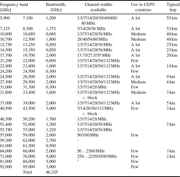
Table 5.4 shows frequency allocations for fixed wireless service. It is a generic table for ITU Region 1 (Europe etc.) and does not specify exactly how frequencies are used in a specific country. Frequency regulation is carried out under internationally agreed principles, but under national authority. Principles of how frequency licenses are granted vary. Table 5.4 also gives information about band usage in CEPT-area and typical MW radio hop lengths.
Lower frequency bands 6...13 GHz are deployed for long trunk lines usually in rural areas. Hop-lengths are tens of kilometers. In some countries there may even be minimum allowable hop length limitations for below 10 GHz hops to ensure efficient use of frequency spectrum. Old long-haul bands below 6 GHz are too narrow for modern transmission and many of them have already re-allocated to mobile service.
Frequency bands 23...38 GHz are very popular for urban installations. Hops are 5...15 km long. Antennas are smaller and these radios fit very well to urban BTS installations. The number of wide channels (28/56 MHz) is very limited and in many cities these channels start to be congested.
New bands 32 GHz and 42 GHz are being opened in many countries to ease the need for high capacity backhaul (LTE). Also millimeter wave (mmW) bands in the range 50...90 GHz are coming onto the scene. For example, bands 57...66 GHz and 71...94 GHz are now widely under consideration for future small cell wireless backhauling. Frequency regulation is done or under preparation in several countries for these bands. Commercial semiconductor technology is available and research projects ongoing on how to make that technology more inexpensive. According to ITU-R frequencies up to 400 GHz are considered as radio frequencies. Between 40 – 275 GHz there are frequency allocations for fixed traffic 131 GHz altogether. There are several 5...10 GHz continuous (paired/un-paired) bands available that enable over 10 Gbit/s transmissions.
Also, frequencies below 10 GHz have gained interest in mobile backhaul. They offer an alternative for backhauling in non- or near-line-or-sight environment using low-cost hardware known from WLANs and mobile BTSs. A drawback is limited spectrum and increasing usage; for example 5.8 GHz RLAN band have a bandwidth of about 250 MHz. Even BTSs/eNB's themselves and the frequencies they employ for mobile traffic could be used for backhauling. This technique is called relaying or in-band/out-band backhauling. It makes mobile network roll-out and network planning easier when there is only one technology to consider. The drawback is that backhauling eats up the valuable mobile spectrum.
Table 5.4 Frequency allocations for fixed service.
One key factor when evaluating the total cost of radio link is the frequency license fee. It is typically paid annually and for traditional point-to-point radios it is paid per every hop. Level of license fees varies a lot between countries, from a small fee to auctioned market price that creates a significant cost for the MWR user. License fees are typically associated with frequency (interference) co-ordination done by a national regulator for each and every radio transmitter. From the fee point of view unlicensed bands may be an attractive alternative. But, on the other hand, lack of co-ordination also increases the risk of costs due to non-functioning backhaul. In some bands and in some countries a system called light licensing is introduced. A licensee makes him/herself a reservation using a web-application on a first come first served basis.
5.2.3 Network Topologies
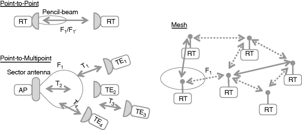
The basic topologies for radio link technology are point-to-point, point-to-multipoint and multipoint-to-multipoint. Point-to-point links establish radio connection between two points – near-end and far-end – with narrow beam called pencil-beam (Figure 5.9). With MW radios there must be line-of-sight (LOS) between the ends. Duplex communication takes place with FDD. Point-to-point is by far the most common MWR topology used in the MBH networks – the point-to-point MWR links can then form various network level topologies depending on the density and location of base station sites; sometimes rings or other ‘closed’ topologies are used to enable network level protection (have an alternative route for the base station connection).
Point-to-multipoint topology or architecture is also called point-to-area because PMP access-point (AP) provides coverage in a similar way as a mobile base-station. Typically economies go so that one AP is several times (3...5) more expensive than a terminal equipment (TE). Access technology is often TDD that enables different temporary capacity needs to be adapted per TE. The main difficulty in adopting PMP MW system is often the line-of-sight requirement – it can be difficult to have LOS for so many base station sites within the (theoretical) coverage area of the AP that it grants PMP system feasibility.
Multipoint-to-multipoint or (partial) mesh topology enables complex networks that can utilize packet transmission protocols to make advanced load sharing, routing and protection. Today mesh is not much in use in MBH while the technology and its benefits are under study.
Figure 5.9 Examples of wireless network topologies: Point-to-point, Point-to-Multipoint, and Multipoint-to-Multipoint/Mesh. RT = Radio Terminal, TE = Terminal Equipment, AP = Access Point.
When looking at larger microwave radio network topologies they can be classified as tree, chain, star and ring, or a mixture of all these. The most common microwave radio link network topology is tree. In tree the capacity is carried to the access leaves through higher capacity trunk lines. It is a well proven way to build networks. Tree sets higher reliability requirements to trunk lines. Some branches of the tree may contain a chain of several links. In star topology capacity is distributed from one point to several directions. Ring is a kind of chain with both ends connected. Ring topology is an efficient way to bring redundancy to the network, but it also requires special protocols.
Availability of frequency channels, access method (TDD/FDD) and geography sets also limits to the network topology selection.
Point-to-multipoint topologies are typically used in broadband wireless access (BWA) systems that provide fixed wireless access for a certain geographical area.
Mesh topologies are used commonly in consumer wireless access systems like WLAN.
5.2.4 Availability and Resiliency
To protect against hardware failures microwave radios can be installed in stand-by configuration (Figure 5.10). It is typically a 1:1 configuration where protective radio (TRX) is ready to take over the traffic if the working radio fails. Both the working and redundant radios occupy the same frequency channel. In the other end change-over is not needed, but control channel is used to indicate the loss of signal.
Figure 5.10 Radio link protection.

Typically the Mean Time to Failure (MTTF) is shorter and repairing takes more effort for radio equipment located outdoors, if compared to switching equipment in indoor premises.
Figure 5.11 Radio link diversity configurations.
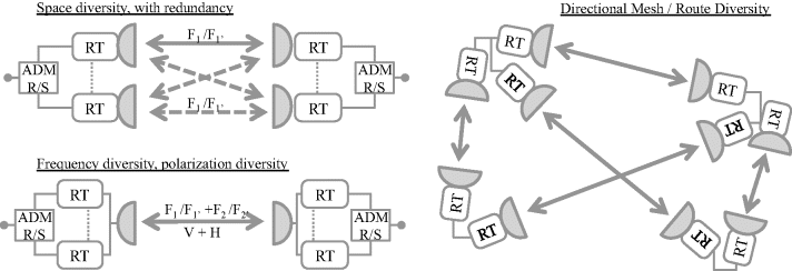
Radio hop protection methods are called diversity methods and they operate as 1+1. Most common are (Figure 5.11):
- Space Diversity (SD): two antenna separated vertically.
- Frequency Diversity (FD) or Polarization Diversity (PD): two frequencies or polarizations in one antenna.
- Route Diversity (RD): protective path is horizontally separated.
Only route diversity is an effective mean against rain attenuation. Other methods are mainly used against multi-path diffraction attenuation in lower frequencies (Section 5.2.1). Equipment and hop protection can be combined, for example stand-by mode with diversity. There is more about backhaul resilience in Chapter 09. Diversity and resiliency configurations usage in MBH access network is decreasing due to installation and cost requirements, and also because the mobile network itself provides resiliency. N+1 type of redundancy is still used in trunk networks.
Ethernet ring provides reliable multi-point connectivity, but at the same time protocol must avoid loops. Two basic principles to make Ethernet rings are:
- open loop: when protection is required block the failed link;
- closed loop: when protection is required, steer traffic regardless of spanning tree protocol.
There are numerous Ethernet ring protocols; some of them are standardized, some proprietary. Typically, support for different loop types is required: single loop, overlapping loops and conjoined rings (loops with common nodes). Ethernet Ring Protection (ERP) is a L2 mechanism. It uses control VLAN for monitoring and control and Payload VLAN for data. Each payload VLAN is assigned to the control VLAN which is managed by one of the switches that act as a master. During normal operation ERP master blocks the ERP payload traffic preventing loops. Link failures are detected by 1) loopback packets stop circulating around the ring, or 2) ERP-aware switches report detected link failure to the master.
Ethernet ring protection recommendation (G.8032/Y.1344) defines automatic protection switching (APS) for Ethernet ring topologies. Loop protection is achieved by ensuring that traffic may flow in all but one direction at a time. Ethernet rings support a multi-ring network that consists of conjoined rings. APS protocol is used to control projection over the ring. Under specified conditions the switching time in case of failure in the Ethernet ring shall be less than ‘magical’ 50 ms.
5.2.5 Performance
One step in radio link dimensioning is to set the target availability level for the whole backhaul network. Some recommendations for large telecommunication networks can be found from [T-REC-G.826 or G.828]. In data networks and mobile backhaul the last miles target availability levels are key parameters to optimize network cost and customer perceived quality. It is always a balancing act between the total availability in network level taking into account the customers, mobile services and business case.
Radio link performance indicators are defined in ITU-T G.826. Errored Block (EB) is a block in which one or more bits are in error. Consecutive bits associated with a path form a block. Errored Second (ES) over the whole path is a one-second period during with there is one or more errored blocks or at least one defect. Over a single connection ES period also occurs when Loss of Signal (LOS) or Alarm Indication Signal (AIS) is detected. Severely Errored Second (SES) is a one-second period which contains ≥30% errored blocks or at least one defect. SES is a subset of ES. Over a connection during SES bit-error ratio ≥ 10−3 or during which LOS or AIS is detected. Background Block Error (BBE) is an errored block not occurring as part of an SES, i.e. a sporadic error under good signal condition. [9]
These standard performance figures are typically recorded in every node and used to characterize the wireless backhaul quality. They are also monitored for end-to-end paths and may be used to verify SLA conformance.
Respective performance parameters related to the measurement time are Errored Second Ratio (ESR), Severely Errored Second Ratio (SESR) and Background Block Error Ratio (BBER). There are also error performance definitions for SDH and ATM cell-based transmission.
5.2.6 Other Wireless Technologies
One wireless technology often mentioned when high capacities are needed is Free Space Optics (FSO). It means using high intensity modulated laser beams for transmission. FSO products and application have existed for a long time for high-capacity data networking while they have not gained a market share in mobile backhauling. The main reason is because of still quite clumsy and expensive technology and low availability due to atmospheric (fog) attenuation.
Satellite connections are also used for mobile backhauling in some cases. Typical applications are in sparsely populated areas where other transport systems are even more expensive than satellite. Transport from geostationary satellites is not optimum because of ground station requirements (for backhaul capacities) and long latency. Recently there have been proposals to provide backhaul capacity from Medium Earth Orbit (MEO) satellites with link budget and latency that meets MBH requirements.

