CHAPTER 2
Storage Infrastructure
In this chapter, you will learn how to
• Outline how a SAN works
• Explain how a storage array works
• Identify DAS technologies
• Describe the types of NAS and how they are used
• Identify cloud storage types and storage methods
With the amount of data organizations are managing these days, it is quite easy to outgrow the capacity of a local server or desktop. Storage arrays, network attached storage (NAS), direct attached storage (DAS), and cloud storage offer organizations a way to expand storage depending on the organization’s needs. In some cases, a combination of each of these may be used to provide users and applications with access to information. Storage has become so essential to the continuing operation of a business that the loss of a key application or a storage device would have disastrous consequences, so these devices can be equipped with much more component redundancy to protect against the failure of individual parts or loss of power or network connectivity.
Managing storage on many devices can be complex and costly. Storage can be centralized to more efficiently allocate storage and to more effectively administer storage systems. Centralizing storage has created the need for many devices to connect to the storage.
Storage area networks (SANs) are used to connect many devices to one or more storage arrays. Storage arrays separate storage from individual hosts and consolidate storage for easier manageability. Direct attached storage can refer to storage that is internal to hosts or storage that is connected to a host using an external interface such as SCSI or FC. DAS is usually connected to only one device, but multiple devices can be connected to a DAS; however, DAS differs from a storage array on a SAN in that there are no other network devices in between the hosts and their storage. The devices are directly attached, which is the reason for its name. Network attached storage presents storage to other devices on the network as a network share. These devices can concurrently read and write data from the NAS, and the NAS handles storing and retrieving data from the storage itself. NAS devices are often much faster than server-based file servers, and they are usually built with far more component redundancy. Figure 2-1 shows a storage array connected to several servers and a workstation through a storage network. These servers and the workstation are connected over an Ethernet network to other workstations. In the middle, a DAS is connected to a single server, and on the right, a NAS is connected to several servers and workstations over an Ethernet network.

Figure 2-1 Storage array, DAS, and NAS
The SAN, storage array, DAS, or NAS could be augmented or replaced with cloud storage. Those organizations that choose not to centralize data storage in their own data center or that are too small to justify their own data center often move their storage to the public cloud. Others create their own cloud for sharing storage with departments or other internal groups, or they join forces with other organizations to form a community cloud of shared storage and resources. Public and private cloud strategies can also be merged into a hybrid cloud to gain some of the benefits of both storage architectures.
Storage Arrays
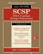
Storage arrays are used to provide multiple devices with access to storage. These devices can interface with the storage in the same way they would interface with local storage. This is important because some resource-intensive applications such as database management systems (DBMSs) will require local access to storage resources. The storage array can boost disk performance and often lower costs. Consider a scenario with five database servers, as depicted in Figure 2-2. Each server needs several logical drives, and those logical drives must be separate in order to prevent I/O, such as the writing of a transaction log from interfering with I/O from a database table modification. A standard drive implementation might include a two-drive mirror for the operating system, three disks in a RAID 5 for the database files, two disks in a mirror for the log files, and another two-disk mirror for the temp files and indexes. So, in the end, this server requires nine disks, and the RAID 5 array is using only three spindles. Five large servers would be needed to house this many disks. Some of the space on the system may be underutilized because temp files and indexes may take up only 25GB to 50GB, whereas the disk size in the server may be 300GB to 600GB.

Figure 2-2 Five database servers, each with local storage
Storage arrays can contain hundreds or even thousands of disks with the use of many disk enclosures. These disks can be configured in different RAID types to support application needs, and multiple logical drives can be created from the RAID groups to be allocated to servers. In the database server example described previously, instead of buying five large database servers, you might purchase five smaller machines with the same processing power and memory but only two disks for the operating system. The storage array configured with a six-disk RAID 5 and two four-disk RAID 10 sets depicted in Figure 2-3 could offer storage to all five servers, and the storage would utilize more spindles, offering greater performance. However, if all five servers heavily access the disk, there could be resource contention, so a real-world scenario might include many more servers with different data needs; therefore, the logical drive would be allocated in such a way as to combine low- and high-impact storage on the RAID set, thus balancing contention on the disks.
Figure 2-3 Five database servers connected to a storage array
Another problem seen with local disks is the difficulty of expanding storage. Consider a file server with a logical drive made from a five-disk RAID set. If the storage needs exceed the current capacity, the entire RAID set must be re-created and a new logical drive created. One option would be to add another physical disk and make it a six-disk RAID set. Another option would be to replace the five disks with larger-capacity disks. Either option would require the organization to back up the data on the logical drive and then restore it once the new logical drive was created. This would result in significant downtime to the users of the file server—which should be avoided as much as possible. This scenario is different when using a storage array. For one thing, many storage arrays allow logical drives to be expanded when more space is needed. If this option is not available, a new drive can be provisioned in the storage array, and the data can be migrated using built-in tools to minimize downtime and expense.
The storage array is modular, so it can consist of one or more pieces that are connected together. The main unit contains one or more controllers and possibly some disk drives. The storage array may contain disk enclosures that house many more disks connected back to the storage array. Figure 2-4 shows the elements of a storage array.

Figure 2-4 Elements of a storage array
Controller Head
The controller head manages the disks, cache, and front-end and back-end ports in the storage array. It keeps track of the RAID arrays and logical volumes, and it maps logical volumes to hosts, places data in or out of cache, and writes data to disks. The controller does exactly what its name says: It controls the storage array. Controllers can be configured as a single unit, as dual units, or in a grid.
Single
Single-controller storage arrays can be implemented at a lower cost than dual-controller units because single units minimize the number of front-end connections and ports to hosts or the fabric as well as the number of back-end ports to disk enclosures. Both front-end and back-end components need to connect only to a single device. Single-controller storage arrays typically cost less than a dual unit. This, coupled with the requirement of fewer cables, makes the solution less expensive than a dual unit. The disadvantage of this cost savings is that the controller is a single point of failure. The storage array will become unavailable if the controller fails because all I/O operations for the storage array are handled by this one controller.

EXAM TIP Questions asking for the least expensive solution could use single controllers, but do not choose single controllers for questions requiring redundancy.
Dual
Dual-controller storage arrays are standard in enterprise storage arrays where most components are configured in a redundant fashion. Dual controller units are equipped with two identical controller heads that are each capable of operating the entire storage array. Disk enclosures must have at least one back-end connection to each controller in a dual-controller unit, and each front-end path to a host or switch needs to be cabled to both controllers. Twice as many cables and ports are required to implement a dual-controller unit, and this increases the cost. Dual-controller units are a bit more complex in design than single-controller units because the controllers must be kept in sync so that one can take over the other’s operations in the case of a controller failure.
Dual controllers can be configured in one of two ways. Active/passive configurations route all I/O through a single controller, while the second controller simply stays aware of all I/O. If the active controller fails, the passive controller becomes active and assumes all the duties that were being performed on the failed controller. Active/passive solutions result in consistent performance even when a single controller has failed, but the maximum performance of the unit is equivalent to that of a single controller unit.
Active/active controllers distribute the I/O between both controllers to achieve higher performance. Both controllers stay aware of their counterpart’s operations and will assume those operations if the other device fails. Controller failure does result in a loss of performance while the storage array is operating on a single controller. Keeping the two controllers in sync while both are performing work requires more complexity, leading to a higher cost for active/active controllers.
Grid
Grid storage, also known as scale-out storage, is a group of low-cost storage arrays or servers that operate together to provide fast and reliable access to data.
Grid implementations can either store entire files on a node or break up the files into segments to be stored on multiple nodes in a process known as encoding. Storing an entire file on a single grid node is simpler to implement, but retrieving the data relies upon a single node in the grid, so the performance is limited to the capabilities of that node. File writes are spread across the nodes in the cluster to aid in balancing the load, but reads must be directed at the node that contains the file, so it is possible for the grid to be unbalanced if some nodes contain data that is frequently accessed. Files are typically replicated to other nodes in the cluster to protect against node failure.
The grid encoding process breaks files into blocks that are spread across multiple nodes in the grid. Parity blocks are computed and stored to protect against node failures. The process is similar to RAID striping and parity. Grid file systems can be assigned a protection level that governs the maximum number of nodes that can fail before data loss occurs. Additional parity data is computed for higher protection levels, and a grid can support many different protection levels. Encoding results in better performance because more nodes can be used to retrieve files, but this increases grid management complexity.
Front-end nodes manage the I/O on the grid by identifying the nodes on which to write files or encode blocks. They keep a table mapping files to their locations within the grid to service read requests and track file locks and metadata. Grids require multiple front-end nodes for reliability, and these nodes require more processing power than other nodes in the grid. Some grid implementations spread the front-end management across all nodes in the grid, while others dedicate several powerful machines for the task. A back-end network connects the grid nodes, and this network must support high throughput and be separate from the front-end network. A write of a single file to the grid results in at least two writes for file grids and many more for encoded grids, and each frame on the network results in overhead that the network will need to absorb.
Both the front-end and distributed grid management models require a node in the grid to perform work before the data can be stored on the grid, which can increase latency. A third option has been developed to address this issue by installing a virtual controller on each host that needs to connect to the grid. The processing of management tasks is pushed to the client system. The virtual controller determines where to encode the data in the grid and keeps track of file mapping, locks, and metadata so that files can be written directly to the grid nodes that will store the data.
Cache
Cache is high-speed memory that can be used to service I/O requests faster than accessing a disk. Controller head cache is used for storing data that is waiting to be sent over the interface in response to a read request or data that is waiting to be written, or flushed, to the disks in response to a write request. Data may also remain in cache when the controller head considers it likely that the data will be requested for further read or write operations. When a request is made for data that exists in cache, it is known as a cache read hit. The storage array can immediately service the request by sending the data over its interface without retrieving the data from disk. Cache read hits result in the fastest response time. When requested data does not exist in cache, it is known as a read miss.
EXAM TIP Having more cache read hits results in better performance. Optimize cache to maximize cache read hits.
Cache is referenced and organized by pages. Pages store data as well as a link to the location of the data on disk and a value called a dirty bit. The dirty bit is set to on when data is new or changed in cache, and this tells the controller head that the data needs to be flushed to disk.
• Read ahead Read-ahead cache retrieves the next few sectors of data following what was requested and places that into cache in anticipation that future requests will reference this data. The read-ahead cache results in the best performance increase with sequential data requests, such as when watching videos, copying large files, or restoring files.
• Write back Write-back cache sends an acknowledgment that data has been successfully written to disk once the data has been stored in cache but has not actually made it to disk yet. The data in cache is written to disk when resources are available. Write-back cache results in the best performance because the device is able to accept additional I/O immediately following the write acknowledgment. However, write back is riskier because cache failures or a loss of power to the disk could result in a loss of pending writes that have not been flushed to disk.
• Write through Write-through cache waits to send an acknowledgment until a pending write has been flushed to disk. Write-through cache is slower than write back, but it is more reliable.
Cache is much more expensive per gigabyte than hard disks, and it is typically volatile, meaning that the data remains in cache only when power is provided to the device. A loss of power results in a loss of data in cache. Because of this, storage array controller heads must manage cache by flushing pending writes (dirty data) out to disk and freeing up space for new reads and writes. If cache is full when a new write is received by the controller, some data will need to be removed before the controller can cache the new write. This causes a write delay, so controller heads try to manage cache so that there is a healthy amount of free space available for new requests. The high watermark is a threshold where too much data resides in cache.
There are two methods used for freeing up cache space, and they operate based on opposite assumptions. The first method known as most recently used (MRU) assumes that applications are least likely to need the data they just requested, so it frees up pages with the most recent access dates. Conversely, least recently used (LRU) assumes that data that has been in cache for a long time since its last access is least likely to be requested, so it frees up pages beginning with the oldest access dates. Thus, MRU releases the data that was accessed from cache most recently, while LRU releases the data that has remained unused in cache the longest.
Expansion Adapters
Storage arrays are often modular units that can be upgraded much like a workstation or server by using expansion adapters. Upgrades include adding more front-end or back-end ports, additional cache modules, or NAS ports. Unless you are using a server with a storage operating system on it, these expansion adapters will need to be purchased from the vendor.
Array Port Types and Cabling
Front-end ports are used for host connectivity. Figure 2-5 shows the front-end and back-end ports connected to a storage array and how they connect to disk shelves and a switch. Hosts will directly connect to these ports or, more commonly, connect through a SAN via a switch. The front-end ports need to be configured to work with the transport protocol that is in use on the network such as FC, Internet Small Computer System Interface (iSCSI), or Fibre Channel over Ethernet (FCoE). Back-end connections will use whichever technology is specified by the array such as FC or Serial Attached SCSI (SAS). Protocols are covered in more detail in Chapter 3.

Figure 2-5 Storage array back-end and front-end port connections
The key to installing a storage array is to cable it redundantly. If the storage array is using more than one controller, both controllers should be cabled to disk enclosures. However, controllers may not be connected to all of the disk enclosures because some back-end connections can be chained from one disk enclosure to another.
Likewise, front-end ports should also be cabled redundantly. The storage array should have a front-end port from each controller connected to a redundant link on a host or fabric so that either controller can take on the load of the array if one controller fails. Single-controller units may also be cabled redundantly, but the redundancy will protect only against cable or port failure, not controller failure.
Disk Enclosure
Disk enclosures are used to hold additional disks in a storage array. Storage arrays can be expanded with many disk enclosures. Some support so many enclosures that it takes several racks to house them all. The number of supported disk enclosures is primarily determined by the controller capabilities, including the number of back-end ports.
Disk enclosures vary based on the following factors:
• Number of supported disks
• Size of supported disks (2.5 inch or 3.5 inch)
• Interface
The number of disks an enclosure can support is often a critical factor for expansion. Each enclosure takes up valuable space in a rack, but this can be minimized through the use of high-density enclosures. These enclosures come at a higher cost than low-density enclosures. There is no one standard for the number of disks in a low- or high-density enclosure, but low-density enclosures typically have between 12 and 15 disks in them, and high-density enclosures will typically have between 40 and 60 disks. Disks are loaded into low-density enclosures through the front of the enclosure, as shown in Figure 2-6. This makes it easy to swap out or add a failed disk.

Figure 2-6 Low-density enclosure
To swap out a failed disk in a low-density enclosure, follow these steps:
1. Identify the disk to swap out. In the case of a disk failure, this would be indicated in the management software for the array, and the disk usually has a light to indicate its status. Green is good; an amber or red light indicates a problem.
2. Unlock and remove the front bezel from the disk enclosure with the failed disk.
3. Put on an electrostatic wrist strap and attach it to a ground.
4. Pull the tab on the failed disk tray to release it. Firmly pull on the exposed part of the tray to remove the disk. Do not pull on the tab to remove it because this could break off the tab or misalign it.
5. Wait 30 seconds for the disk to stop spinning and for the heads to land in their landing zones.
6. If the replacement disk did not come with a tray, remove the failed hard disk from the tray and mount the replacement disk in the same tray. Skip this step if the replacement disk came with a tray.
7. Open the tab on the disk tray and then insert the tray with the replacement disk into the enclosure with the tab facing the same direction as the other disks in the enclosure. Slide the disk in until the tab is against the enclosure and then close the tab until it snaps into place. The tab should pull the disk in a little more so that it is snug with the enclosure and level with the other disks. If the disk is not level, pull the tab and repeat so that it is seated properly.
Disks in high-density enclosures are accessed from the top of the enclosure, as shown in Figure 2-7. The enclosure slides away from the rack to expose the top of the unit for disk additions, removals, and replacements.

Figure 2-7 High-density enclosure
Follow this procedure to replace a disk in a high-density enclosure:
1. Identify the disk to swap out. In the case of a disk failure, this would be indicated in the management software for the array, and the disk usually has a light to indicate its status. Green is good; an amber or red light indicates a problem.
2. Unlock and remove the front bezel from the disk enclosure with the failed disk.
3. Put on an electrostatic wrist strap and attach it to a ground.
4. Release the enclosure top cover by pressing a release button or by removing top screws.
5. Pull the tab on the failed disk tray to release it. Firmly pull upward on the exposed part of the tray to remove the disk. Do not pull on the tab to remove it because this could break off the tab or misalign it.
6. Wait 30 seconds for the disk to stop spinning and for the heads to land in their landing zones.
7. If the replacement disk did not come with a tray, remove the failed hard disk from the tray and mount the replacement disk in the same tray. Skip this step if the replacement disk came with a tray.
8. Open the tab on the disk tray and then insert the tray with the replacement disk into the enclosure with the tab facing the same direction as the other disks in the enclosure. Slide the disk down slowly until the tab is against the enclosure. Do not drop the disk tray into the enclosure because this could damage the disk or the interface connection. Close the disk tray tab until it snaps into place. The tab should pull the disk in a little more so that it is snug with the enclosure and level with the other disks. If the disk is not level, pull the tab and repeat so that it is seated properly.
Enclosure Controllers
Disk enclosures are equipped with controllers to send I/O over the back-end ports back to the storage array and to manage the disks in the enclosure. The controllers contain the intelligence to connect the enclosure to the rest of the storage array.
Monitoring Cards
Enclosures may also contain monitoring cards that track the health of enclosure components and report to the system. Alerts can be set up to track critical events such as a hard drive failure, path failure, or loss of connectivity to a device. Statistics can be calculated to obtain a performance baseline and to identify performance problems later.
Enclosure Addressing
The storage array must address each of the enclosures in order to send and receive traffic to and from it. This addressing takes place on the back end of the storage array, meaning that the addresses are used for communication inside the storage array, as compared to front-end ports, which have an addressing scheme used to communicate between the storage array and hosts. Addressing the back end uses some of the same protocols that front-end communication does. Current enclosures use either FC or SAS connections. FC addressing uses a 64-bit World Wide Name (WWN) as an address, and SAS uses a 64-bit SAS address. The 64-bit address space for FC WWNs and SAS addresses would allow for 18,446,744,073,709,551,616 unique addresses, but FC is limited to about 15 million devices because of its use of 24-bit port IDs and area IDs. SAS is limited to 65,536 devices.
Cabling
The key to installing a storage array is to cable it redundantly. If the storage array is using more than one controller, both controllers should be cabled to disk enclosures. However, controllers may not be connected to all of the disk enclosures because some back-end connections can be chained from one disk enclosure to another.
Hot-Swap
Various parts of the storage array are hot-swappable, meaning they can be removed without powering off the device. Such devices include power supplies, interface cards, hard disks, controllers, and fan units.
Each unit in a storage array is usually configured with dual power supplies that are connected to different circuits and uninterruptable power supply (UPS) units called A/B power, where A and B are the different redundant circuits. Power distribution units (PDUs) within the rack or mounted close to the rack are similar to surge protectors, and each power supply for the A power will be connected to the A PDU, while the B power supplies will be connected to the B PDU. Each PDU connects back to a circuit leading to a different UPS.
Storage Area Networks
A storage area network connects one or more storage arrays with one or more hosts. This allows the storage in storage arrays to be shared among the hosts in the SAN and for hosts to access the shared storage of multiple storage arrays to meet their performance and capacity needs. SANs allow for data storage to be physically distant from the hosts that access it. SANs connect hosts and storage arrays together via protocols such as FC, iSCSI, FCP, iFCP, or FCoE. These protocols are discussed in detail in Chapter 3, but an overview of the two most common protocols, FC and iSCSI, is provided here.
Fibre Channel
Fibre Channel is a networking technology used to transmit data at high speeds. Current FC technology can transmit data at 16 Gbps (roughly 2,000 MBps), primarily over optical cables and to a lesser degree on copper cables. FC is expected to operate at 32 Gbps by 2014. At its release, FC outclassed its primary competing technology, Small Computer System Interface (SCSI), with support for many more devices on a single network and a longer range of operation.
Fabric
The most common way of connecting FC devices into a SAN is through a fabric. A fabric, discussed more in Chapter 3, is an interconnection of FC devices through FC switches. Each FC switch can handle multiple connections between devices, and each connection is isolated from other connections to improve security and to provide dedicated bandwidth to the connection. Similarly, iSCSI uses Ethernet switches that also isolate traffic. Both FC and iSCSI switches are a central point where devices can connect, and each can be expanded through connections with other switches.
FC or iSCSI Protocol
Internet Small Computer System Interface has experienced much growth because of its lower cost and ease of implementation as compared to FC. iSCSI utilizes common low-cost Ethernet equipment and cabling to connect storage devices and hosts over a SAN. The advent of 10GigE, which is Ethernet that has a maximum throughput of 10 Gbps, has allowed iSCSI to achieve speeds approaching those in FC networks (2 Gbps to 16 Gbps). The cost of 10GigE equipment currently negates much of the price advantage iSCSI has over FC; however, this may change as industry adoption of 10GigE increases.
iSCSI runs over Ethernet, which has higher overhead than FC. Ethernet can typically achieve 50 percent to 85 percent of its rated capacity, while FC can consistently achieve 90 percent of its rated capacity. This is why 10GigE iSCSI is considered roughly equivalent to 8 Gbps FC.
An FC host bus adapter (HBA) is required to connect to an FC network. The FC HBA performs the processing necessary for handling FC data. However, with iSCSI, a standard network interface card (NIC) can be used, which will create processor overhead as the CPU handles the TCP/IP stack. NICs equipped with TCP Offload Engine (TOE) can alleviate some of this, and iSCSI HBAs have even more capabilities built in to reduce processor overhead and improve response time. Both are discussed in more detail in Chapter 4.
Block Mode
Storage area networks present data to hosts as local storage appears so that hosts can interact with the storage on a block level. As mentioned in Chapter 1, hosts reference locations in storage by block. With a SAN, a host can write data to a block on storage that is allocated to it, and the storage network carries the commands from the host to the storage array located somewhere on the SAN. The storage array then writes the data out to disks within it.
File System on Host
Once storage is presented to the host by the SAN, it is up to the host to partition and format the storage for use. This was introduced in Chapter 1. Different operating systems use their own file systems to organize data on the disk. Enterprise servers commonly run versions of Microsoft Windows or Unix/Linux, and while Linux does support reading Microsoft’s New Technology File System (NTFS), Linux disks commonly use the ext (extended) file system. The latest version of ext is version 4, termed ext4. Ext4 supports file systems up to 1.15 exabytes (EB) and file sizes of 17.5 terabytes (TB). An exabyte is 1,000 petabytes (PB), or 1,000,000TB. Ext4 achieves extremely fast file system checking by marking unused portions of the volume so that they can be skipped during a check. Delayed allocation buffers data writes so that they can be written to contiguous space and avoid fragmentation for new writes. However, delayed allocation increases the risk of data loss if power is lost to the computer before data is written to disk. Ext4 is backward compatible with other ext versions, and it is journaled. Journaling is a process where changes are tracked in a log, known as a journal, before saving the change to the file system. Journaling provides better protection against data loss or corruption in the case of a power failure. Without journaling, data that was partially written to a disk would be unreadable, but journaling would allow for the missing portion of the write to be completed once power was restored to the disk.
Microsoft systems formerly used the FAT and FAT32 file systems, but these have been replaced by NTFS and Microsoft’s latest file system, ReFS. NTFS was introduced in Microsoft Windows NT. NTFS allows you to control which users have access to individual files and folders, whereas previous Microsoft file systems allowed access controls only when files were shared over the network. NTFS also supports compression and encryption on files and folders. ReFS was introduced in Microsoft Windows 2012, and it offers greater protection against file corruption and support for even larger file systems than NTFS.
Direct Attached Storage
Direct attached storage is an easy way to expand the available storage space for one or more computers. DAS is a storage array that is cabled to one or more hosts without any devices in between. In some cases, DAS is used to refer to the local storage on a device, but in most cases, DAS is a device external to the host. In these cases, the DAS connects to a host through one or more front-end ports such as SCSI, SAS, eSATA, or FC. The DAS may have multiple types of ports as well such as FC and SCSI. The number of hosts that can connect to the DAS is limited by the quantity of front-end ports on the DAS.
SCSI
Small Computer System Interface (SCSI) DAS connects to a SCSI HBA on a host and is assigned a SCSI ID. Each SCSI device will need to have a unique SCSI ID, including the SCSI controller. The controller is typically assigned the ID of 7, so make sure that the DAS or other devices connected to the SCSI chain do not conflict with each other. Each end of the SCSI bus needs to be terminated. This may be implemented in the DAS, or it might require a terminator to be installed on the device. There will be two SCSI connectors, one for the connection to the server and another for a connection to another device on the chain or for termination. If the DAS does not terminate itself, ensure that a terminator is connected to the device at the end of the chain.
Many different devices can be mixed in a SCSI chain, but this can introduce problems if all devices are not operating at the same speed. One slow device on the chain will require all other devices to communicate at that slower speed and can result in significant performance issues for the DAS.
SAS
Serial Attached SCSI (SAS) DAS devices are a direct connection from DAS to the host, so there are no other devices sharing the connection such as with SCSI. A host may be connected to the DAS via multiple SAS connectors to obtain greater redundancy if one link fails and to increase the throughput to the DAS. SAS offers up to 6 Gbps speeds, and each connection does not have to share this 6 Gbps with other devices as is the case with SCSI.
eSATA
eSATA DAS connects much like SAS with a single port on the eSATA DAS connecting to a single port on the host. eSATA offers up to 6 Gbps speeds, but it does not offer the features of SAS.
FC
Fibre Channel connections offer high speeds for DAS. The type of connection used is called FC point-to-point (FC-P2P) because the DAS and host are directly connected to one another. The host must have an FC HBA to connect to the DAS. These FC HBAs can be expensive compared to SCSI, SAS, and SATA, but FC DAS can be connected over longer distances.
Network Attached Storage
Network attached storage is a storage technology used to share files with many users. The previous technologies discussed in this chapter presented a portion of their available storage to a host to use as if it were local storage. With the exception of clustered nodes, each node can access only the storage that has been presented to it. However, with NAS, storage is made available to many computers at the same time over an IP network through the use of virtual directories called shares.
The concept of file sharing is not new. In fact, it was one of the drivers for initial network adoption in companies. Before the use of shares and the servers that shares reside on, known as file servers, users had to transport data from one computer to another, most commonly via floppy disk. This method of data sharing is known as sneakernet because people have to walk to another computer to share files. So, how does NAS differ from the shares that have become so commonplace in networks today?
NAS offers organizations a way to consolidate and increase availability. As companies create more and more data, much of the files users work with on a day-to-day basis are stored on file servers. File servers are good for storing small amounts of data that is used by a select number of users. However, as the amount of data and the number of users grows larger, file servers cease to be able to keep up with the load. Some servers utilize DAS to access more disks at the same time. These servers may also utilize many network cards to service requests, but even with all this, the operating system that services requests must run in software, and this adds a delay to the servicing of user requests.
Network attached storage provides a flexible way to access files over a network. NAS is built from the hardware level on application-specific integrated circuits (ASICs) to service requests for files, making them much faster than general-purpose file servers. NAS can be equipped with many network interface cards, large amounts of cache, and multiple high-performance processors. As with the other storage technologies discussed thus far, NAS comes in many varieties to suit numerous organizational needs. NAS can have integrated storage on the device, or it can operate in “gateway” mode where it maps storage from one or more storage arrays on a SAN. Many NAS devices also support clustering for high availability. Clustered NAS devices operate under the same name and retain copies of the data on each NAS node or point back to a shared storage location such as a storage array. If a single NAS node becomes unavailable, client file requests will be serviced by other members of the cluster.
NAS can support multiple different protocols such as CIFS for Microsoft clients, NFS for Linux, or FTP for Internet users, making it ideal in environments where multiple operating systems are utilized. Some NAS run services that allow them to act as backup repositories, host web sites, stream audio and video, and more.
Shares are created by assigning a share name and permissions to a directory on the system. The share name can be different from the directory name, and shares do not have to be created in directories directly beneath the root. A share can be created on a subdirectory of a directory that is already shared. This may be necessary in situations where some users need access to only a subset of the information in a share. These users would be given permission to the shared subdirectory, and others who need access to the entire set of directories would be given access to the share above it. Both shares, however, will be seen with their own names at the same level underneath the NAS name when users browse to the NAS by name. For example, say marketing has the folder structure shown in Figure 2-8. Marketing managers and salespeople need access to the entire Marketing directory, but graphic designers who create marketing materials need access only to the Materials directory underneath Marketing. The NAS administrator would create a share called marketing for the Marketing directory and give access to the marketing managers and salespeople. The administrator would then create a second share called materials that would map to the Materials directory underneath Marketing. This directory would be shared to the graphic designers.

Figure 2-8 Sample folder structure
It is important to understand the expected utilization and performance requirements for shares so that they can be provisioned appropriately. Shares with high-performance requirements or high load might need to be on a separate set of disks, whereas multiple low-performance shares or those that are infrequently used could reside on the same set of disks. Growth is also a concern for share placement. While most NAS devices allow for share expansion, it is still best to place shares in a location where they can grow naturally without the need for administrative intervention.
Components
The basic components that make up a NAS include processors, memory, NICs, power supplies, an operating system, and a management system. NAS with internal storage will also have the components mentioned in the “Storage Arrays” section, such as controllers, disks, disk enclosures, and back-end cabling. Gateway systems will have a connection to a storage array on the storage network via the storage network’s transmission medium such as fiber or copper.
One or more processors perform the computations necessary for servicing I/O. Memory is used to store data that the processors are working on and to keep track of open files, metadata, and communication sessions. NICs provide the connectivity to the servers or workstations on the network. A NAS device may utilize many NICs aggregated together to obtain greater bandwidth, and NICs are usually cabled to redundant switches to avoid downtime if a switch, cable, or port fails. The NAS will have at least one power supply to provide power to the various NAS components, but NAS devices are often equipped with more than one power supply to guard against the failure of a single power supply or a loss in power to a circuit. Power supplies should be connected to different PDUs, which go to different UPS units and circuits. The operating system includes the instructions necessary for the NAS to function, and the management system allows administrators to create shares, view statistics on the NAS, join the NAS to a domain, create file systems, and perform many other tasks related to managing the device.
UNC-Addressable Storage
Resources on NAS devices can be referenced by using a uniform naming convention (UNC) path. The UNC path consists of a device name, share name, and filename. For example, to access the October2013.xls spreadsheet in the accounting share on the NAS named userfiles.sampledomain.com, you would type the following into a browser, Windows Explorer, script, or run command:
\userfiles.sampledomain.comaccountingOctober2013.xls
The path begins with \ to tell the application that this is a UNC path. This is followed by the NAS name and a backslash and then the share name and another backslash. When the file is contained within other folders inside the share, these folders will be referenced following the share name and before the filename, such as in the following example, where the file is contained within a folder called October inside the Q3 folder in the accounting share:
\userfiles.sampledomain.comaccountingQ3OctoberOctober2013.xls
Both of these examples use the fully qualified domain name (FQDN) for the NAS device, but computers that are local to the domain would be able to drop the domain suffix (sampledomain.com), so accessing the previous directory from computer1 .sampledomain.com could be achieved with the following path as well:
\userfilesaccountingQ3OctoberOctober2013.xls
TCP/IP-Based Storage
Data read and write requests are encapsulated into packets that are sent over the TCP/IP protocol suite to the NAS. The NAS puts together the packets to reconstruct the read or write request. This request may be CIFS or NFS (discussed in the next section) or other TCP/IP protocols such as File Transfer Protocol (FTP), Secure FTP (SFTP), or Hypertext Transfer Protocol (HTTP).
The NAS receives the read or write request and identifies the location of the data on its block-level storage, either locally or on a storage array if the NAS is operating as a gateway. Data is then written to the storage or read from the storage and sent to the requesting host via TCP/IP.
NAS File System Protocols
Both Windows and Unix systems can use a single NAS device because Common Internet File System (CIFS), the Windows file system protocol, and Network File System (NFS), the Unix file system protocol, are supported.
NFS
NFS is a protocol used for sharing files over a network. It is used on Unix and Linux systems and carries little overhead. The first NFS version was specified by Sun Microsystems in 1984 and was used only within the company. Version 2 of the protocol saw widespread use as a file system protocol. The protocol was designed to have little overhead characterized by its stateless design and User Datagram Protocol (UDP) transport mechanism.
Stateless protocols do not retain information on an overall communication session such as the current working directory or open files, so each set of requests and responses is independent. This requires that each response contain all the information necessary for processing the request rather than relying on the server to know which operation was in progress. The advantage of the stateless protocol is that the NAS does not need to retain information on sessions; in addition, it does not need to clean up information when transactions complete.
UDP is a connectionless transport protocol, which means it does not negotiate with a receiver or check to see whether the receiver is ready before initiating a request, nor does it keep track of packet sequence or errors in delivery. Each of these negotiation and error correction steps would require packets to be sent back and forth, so this time is reduced when using UDP. However, this comes at a cost. UDP has a higher error rate and cannot guarantee receipt of information.
The protocol remained stateless until version 4 where it was modified to become stateful, allowing the protocol to track locked files and open sessions. The protocol ran on top of the connectionless transport protocol UDP in version 2, but version 3 added support for Transmission Control Protocol (TCP), which is connection oriented. Table 2-1 compares the versions.
Table 2-1 NFS Versions

NFS version 4 runs only on top of TCP. Version 4 also added support for a number of other features such as parallel NFS (pNFS), data retention, and session model, but you will not find these on the SCSP exam, so they are not covered in detail here.
CIFS
Common Internet File System is an open version of Microsoft’s Server Message Block (SMB) protocol that is used for sharing files over a network. The initial version of SMB/CIFS suffered from numerous problems, including high broadcast traffic, poor wide area network (WAN) performance, and weak authentication.
CIFS used NetBIOS broadcasts to announce network services. Broadcasts are messages sent to every node on the network, and these resulted in a great deal of additional traffic on the network, reducing its efficiency. This was resolved when NetBIOS was replaced with the Windows Internet Naming Service (WINS) or Domain Name System (DNS) for addressing. CIFS was also designed as a block-level protocol with a 64KB block size. This, along with small window sizes, led to poor WAN performance. Version 1.0 is an improvement on the initial version. In this version, the protocol was changed to be a streaming protocol rather than a block-level protocol, and TCP window sizing was added to achieve better performance on WAN links.
Authentication was also a problem in the initial version of CIFS. LANMan authentication used password hashes that could be reversed to determine the password. This was later replaced with NTLM; however, NTLM poorly implemented the DES encryption standard, allowing for password cracking. NTLM was replaced with NTMLv2 and then Kerberos, which is the current authentication method.
CIFS is a stateful protocol. This gives CIFS the ability to restore connections to shares and files after an interruption, and it can enforce locks on files to prevent users from making changes to files that are currently being modified by another client. CIFS clients can cache files locally by requesting an opportunistic lock (oplock) on the file. Most versions of SMB/CIFS use TCP as their transport protocol; however, earlier versions of SMB/CIFS used NetBIOS or NetWare’s IPX. TCP is connection-oriented, so negotiation takes place between the sender and the receiver to determine capabilities. Acknowledgments are sent after requests to confirm receipt, and packets do not need to contain all the information on a transaction because the server has knowledge of the session between the client and server. Table 2-2 shows the versions of SMB/CIFS and the authentication, addressing, and transport systems used in each, along with the operating systems they were used on and their release year.
Table 2-2 SMB/CIFS Versions

Ethernet-Based Storage
NAS devices are Ethernet-based, using twisted-pair cabling and communicating over a switched network. Ethernet devices are inexpensive compared to other storage technologies such as Fibre Channel or InfiniBand, and most organizations already have an Ethernet network in place, so adding a NAS requires little new investment.
Cloud Storage
Cloud storage is storage that can be accessed over the Internet. Users of cloud storage are distinct from those who manage and control cloud storage. This distinction makes it easier for users, because they are not required to know how the storage is configured in order to use it. Also, this distinction is useful even within organizations to streamline operations, minimize learning curves, and improve support.
Cloud storage can be part of a larger cloud service offering or it can be independent. Other cloud services are discussed in Chapter 9. In a cloud storage model, Internet-connected computers or storage devices offer their storage to users or companies on a subscription basis. Subscription models can be paid, free, subsidized, or simply tracked for accounting purposes. Let’s look at cloud storage types to see how this works in practice.
Cloud Storage Types
Cloud storage types can be differentiated by who has ownership and control of the systems that house the cloud data. We describe these types as public, private, community, and hybrid.
Public Cloud
A public cloud is owned and operated by an organization and made available to customers over the Internet. The advantages of public clouds are the ability to purchase only the IT services that a company needs and the ability to increase or decrease those services extremely quickly. Companies can deploy new servers or services over the cloud in hours rather than days or weeks by using the cloud. Traditional systems would require the purchase of equipment, shipping, installation, and then initial configuration to get them to a usable state. However, the same organization could obtain a public cloud server by simply requesting another server from the cloud vendor. Public cloud resources may be offered for free, but most require a subscription that increases proportionally to usage.
Private Cloud
A private cloud is a proprietary system owned and operated by a single organization for its use. This allows the organization to centralize IT services and tightly control certain elements of IT service administration while providing services to other business groups, departments, or sites. Customers of the private cloud are internal to the organization, but they can utilize the services much like they would a public cloud. The organization may charge those business units for the service, or it may simply track usage through accounting metrics. The primary advantage of a private cloud is that the organization maintains control of the data and systems. Private clouds can reduce inefficiencies in local business group IT functions and better track IT costs, but they do require capital investment to create, and scalability is limited to the investment made into the private cloud infrastructure. Unused capacity is still a cost for the organization as a whole.
Community Cloud
A community cloud is a cloud that is owned and operated by a third party or jointly by members. Community clouds are shared between organizations to reduce IT costs for each member. Such systems are used by educational systems, research facilities, libraries, local and regional government organizations, and businesses. Some examples include county library index systems, state student reporting services, hospital anonymous statistic collection systems, and county sensor collection systems. The primary benefit of a community cloud is reduced costs for IT services to community members. The community cloud can purchase software at better rates by buying in bulk. Economies of scale can be realized because the architecture is larger than what any single community organization could deploy on its own. However, the organization must belong to a group or be associated with others who have the same need and desire to work together. The examples given here are noncompetitive examples. In the corporate world, many of the companies that have similar needs also compete with one another, so they would not want to share their services in a community and would likely utilize a public, private, or hybrid cloud instead.
Hybrid Cloud
A hybrid cloud is a combination of a public cloud and a private cloud. Hybrid clouds allow for sensitive data to be kept in private cloud storage while less sensitive data can be pushed out to public cloud storage. Other hybrid cloud solutions may utilize the public cloud for computing functions and the private cloud for storage functions. This allows the cloud to grow or shrink quickly with greater control retained over the cloud system. Hybrid clouds do require capital investment for the private cloud portion, but the public cloud portion is paid for as it is used. Hybrid clouds can improve performance because private cloud elements can be located close to the users of the system—in some cases, in the same office. This reduces latency for data stored in the private cloud portion of the hybrid cloud solution. Hybrid clouds can use the private element for highly customized user interfaces that may not be supported on existing public cloud architectures.
It is important to note that hybrid cloud architectures are often more complex than private or public cloud architectures alone, and the implementation must utilize industry frameworks for interoperability, which can limit the amount of flexibility the organization has over the application as compared with traditional hosted application models. However, the hybrid cloud model is often seen as a good solution for customers whose requirements do not neatly fit within either the public or private cloud framework alone.
Cloud Storage Methods
Just as there are several types of clouds, there are also several storage methods. One popular method is to use cloud storage for backing up the data that resides on a computer or server. Other methods use cloud storage for primary data storage through mount points, cloud synchronization, or the Web.
Cloud Backup
Cloud storage is also used as a backup destination. Typically, an agent is installed on the location computer or server, and this agent tracks changes to directories that data owners want to back up. The agent can replicate data to cloud storage on a scheduled basis, or the data can be immediately transferred whenever it changes. Cloud backup users are charged for how much storage they utilize. This is important to note because storage sizes can grow quickly depending on how many replicas the organization wants to retain. Cloud backup solutions often allow the user to specify how long data will be retained. The cloud storage vendor will then track changes to the data over that period and retain multiple copies of the data or tracked changes so that individual points in time can be recovered.
Cloud backups often make sense for companies when data growth rates are high and the cost and time to set up new equipment would impact business productivity. It can also make sense for small data sets where the cost to procure, operate, and maintain backup equipment is too significant for the relatively small amount of data that needs to be protected. Cloud backups are discussed in relation to other backup strategies in Chapter 7.
Locally Mapped Cloud Storage
Some cloud systems allow for users to interface with cloud storage just as they would with local storage. Cloud storage systems, in this model, are mounted to the file system and are provided a drive letter or a logical mount point. For example, Figure 2-9 shows that cloud storage residing on server A over the Internet is mapped to a folder called MyStorage on the user’s system drive. Any files that the user stores in MyStorage will actually be stored on the cloud server.

Figure 2-9 Locally mapped cloud storage
Cloud storage can be located far away from the user which requires data transfers to traverse through many hops to reach their destination. Thus, locally mapped cloud storage systems can result in low performance due to latency. Cloud systems utilize local caching to remediate this. Files are stored in a temporary location on the local disk and then changes are flushed back to the cloud storage when permitted. In this way, writes to cloud storage do not have to wait for their writes to be sent to the cloud storage and incur that latency. Instead, they are written to local disk and sent to the cloud storage later. The disadvantage of this option is that failure of the local disk can result in a loss of data when the data has not been written to the cloud yet. Some applications will not be able to tolerate this. These applications may require that the local cache directory be located on a RAID set with adequate redundancy.
Another solution to the cloud storage latency problem is to utilize a cloud service that has cloud storage locations in many places around the world, such that connections are guaranteed a maximum latency.

NOTE Higher latency values mean that it takes more time to travel from source to destination, so lower latency values are desired. In many cases, service level metrics provide a minimum assurance, such as a minimum of 1 Gbps of bandwidth, but with latency you want to have a maximum assurance so that latency does not exceed a specific value.
Cloud Synchronization
Cloud synchronization allocates space on the local drive of a system and replicates that data to cloud storage. New data is written to local storage so that the latency disadvantages of simply mapping to cloud storage are avoided. Furthermore, cloud synchronization can be used to create identical copies of the data at multiple locations. Whenever a write occurs at any synchronization point, the write is replicated to cloud storage and then back down to all the replica sets. Many mainstream cloud storage providers such as Dropbox, Google Drive, Amazon Drive, Microsoft OneDrive, Box, and SpiderOak all use this model.
If we use the previous example here, cloud storage residing on server A over the Internet is mapped to a folder called MyStorage on the user’s system drive using cloud synchronization software. Any files that the user stores in MyStorage will be located on a local logical volume as well as a volume on the cloud server. Server B and workstation A also have the cloud synchronization software installed, and they are associated with the same corporate account. Data that is added on server A will be replicated to the cloud and then pushed down to a MyStorage folder on server B and workstation A. Likewise, files added on server B or workstation A will also be replicated to the cloud and then down to server A. This also works for changes to files and file deletions. This scenario is depicted in Figure 2-10.

Figure 2-10 Cloud synchronization
Web-Based Cloud Storage
Web-based cloud storage is accessed using a browser. Users can log into the cloud storage site and then view their files. Files can be uploaded or downloaded from the site. This model is similar to traditional web storage models such as File Transfer Protocol (FTP) and Hypertext Transfer Protocol (HTTP), which allow users to browse remote storage and upload or download files to the storage location using either a web browser or client software.
Chapter Summary
Storage arrays consolidate storage into a modular unit that has many redundant components. Storage arrays can contain many more disks than would fit into a single server, giving them the ability to create large RAID arrays spanning many spindles for optimal performance. Storage arrays can give hosts access to high-performance RAID arrays and just the right amount of storage for an application without overallocating, as is often the case when storage is local. Storage arrays can be expanded by adding disk enclosures when more storage is needed.
Storage arrays consist of at least one unit that contains controllers, power supplies, front-end and back-end ports, and possibly some disk drives. This main unit can be connected to disk enclosures to expand storage capacity. Controllers handle the reads and writes to the storage array, and they contain large amounts of cache to speed up the response. Cache can be used to store data that will likely be requested in future reads, or it can contain data that will be written to the disk in the future. Controllers can be configured as a single unit in a storage array or with multiple units. A single controller presents a single point of failure for the device, but it is often cheaper than dual controllers. Grids combine multiple low-cost storage arrays to form a larger storage array.
Storage area networks allow multiple storage arrays and hosts to connect together. Fibre Channel and iSCSI are the most common protocols used in SANs. FC offers high-performance storage connectivity with speeds up to 16 Gbps. iSCSI, on the other hand, operates over Ethernet, a standard computer networking medium, so it can be implemented at reduced cost. 10GigE implementations of iSCSI offer similar speeds to those of 8-Gbps FC.
Once storage has been allocated to a host on a SAN, the host will need to create a file system on the storage. Unix systems commonly use the ext file system, and Windows systems use NTFS. ReFS is a new file system introduced in Windows 2012 that is designed with greater protection against file corruption.
Direct attached storage is a storage array that is connected to one or more hosts without the use of a network. The maximum number of connections to a DAS is limited by the number of front-end ports on the DAS. Front-end DAS connections include SCSI, SAS, eSATA, and FC.
Network attached storage differs from the other technologies in that it presents data to devices on the network through shares instead of drives. Many devices can read and write to data on a share at the same time. To protect access to the data, shares are configured with permissions to define who can view the data in the share. Each share maps to a directory on the NAS, and those directories may be local to the NAS or be located on a storage array on a SAN.
NAS shares are accessed by a uniform naming convention path, which takes the following form:
\NASnamesharefoldersubfolderfile
Unix and Linux machines access shares via the Network File System, and Windows devices use the Common Internet File System, an open version of Microsoft’s Server Message Block protocol. NFS began as a stateless protocol running over the connectionless UDP transport protocol, whereas CIFS was stateful, running over a connection-oriented transport protocol. The advantage to a stateless protocol is that it has less overhead, but stateful protocols can track open files and restore lost connections. NFS version 4 is now a stateful protocol running over the connection-oriented TCP protocol. CIFS has undergone many enhancements to improve performance and security.
Cloud storage is storage that can be accessed over the Internet. Users of cloud storage are distinct from those who manage and control cloud storage. Cloud storage types can be differentiated by who has ownership and control of the systems that house the cloud data. Public clouds are owned by third parties. A private cloud is a proprietary system owned and operated by a single organization for its own use. A community cloud is a cloud that is owned and operated by a third party or jointly by members. Lastly, a hybrid cloud is a combination of a public cloud and a private cloud. A third party may have ownership over the public portion of the cloud while the organization has control over the private portion. Organizations can determine which data is stored in the public or private areas and can offer a private interface to public cloud resources.
Cloud storage methods include cloud backup, locally mapped cloud storage, cloud synchronization, and web-based cloud storage. Cloud backup archives data to a cloud storage resource. Locally mapped cloud storage is storage that is available to the local machine as if it were a disk in the machine but it actually resides in the cloud. Cloud synchronization repeats file creation, modification, and deletion to a cloud storage volume and all replicas, and web-based cloud storage is storage that can be accessed via a web browser.
Chapter Review Questions
1. A NAS would be best implemented for which of the following situations?
A. Expanding the storage of a server
B. Creating departmental shares to be accessed by many users
C. Connecting multiple storage arrays to a large group of hosts
D. Interface
2. After reviewing the requirements for a new storage array, you have recommended a mid-level single controller unit. Your manager asks why you chose a single controller. What rationale could you give?
A. High availability
B. Redundancy
C. Manageability
D. Price
3. What term describes a request made for data that exists in cache?
A. Read hit
B. Read ahead
C. Write back
D. Write through
4. Which of the following is the proper way to cable a dual-controller storage array in a SAN?
A. Cable each controller to a separate switch.
B. Cable both controllers to both switches.
C. Cable both controllers directly to the HBAs on a host.
D. Cable both controllers to the WAN ports on the router.
5. In which case would iSCSI be the preferred choice over FC?
A. The company would like to achieve the highest possible data rates.
B. The company wants to isolate the storage traffic from network traffic on a different physical medium.
C. The company would like to present storage to many servers from a single storage array.
D. The company wants to use its existing Ethernet infrastructure for the SAN.
6. Which of the following would not be used to connect a DAS to a host?
A. eSATA
B. iSCSI
C. FC
D. SAS
7. Which address would be used to connect to a NAS share?
A. OE:52:6B:FF:9A:8C:DE:74
B. https://www.snia.org/guidebook.php?user=admin
C. \DetroitstorageFinanceQ3
D. ftp://ftp.storageplus.com
8. Which protocol would be used to create a share for a group of programmers using Linux?
A. NFS
B. TCP
C. CIFS
D. NetBIOS
9. Which type of cloud would you select if you currently have small storage needs that could potentially grow rapidly?
A. Public cloud
B. Private cloud
C. Community cloud
D. Hybrid cloud
Chapter Review Answers
1. B is correct. A NAS would be implemented to create departmental shares to be accessed by many users. NAS devices create and manage shares. These shares can be accessed by many devices and users. This differs from storage arrays, SANs, and DAS, which allocate a chunk of storage to a host. A, C, and D are incorrect. A is incorrect because a NAS is not used to expand the storage of a server. This is a function of a storage array. C is incorrect because a storage area network (SAN) is used to connect multiple storage arrays to a large group of hosts. Lastly, D is incorrect because the choice “interface” is too ambiguous to describe the usage of a NAS.
2. D is correct. From these four choices, price is the only reason why you would choose a single controller over a dual controller. A, B, and C are incorrect. High availability and redundancy are reasons why you would choose a dual over a single controller, and manageability might be slightly less for a single controller but not as much of an advantage as price.
3. A is correct. When a request is made for data that is in cache, it is known as a read hit. The storage array does not need to fetch the data from disk, and it can respond with the requested data immediately. B, C, and D are incorrect. These choices are all methods for managing cache.
4. B is correct. Cable both controllers to both switches. Dual controllers provide redundancy and can be used to balance the load of the storage array, so they should be cabled to prevent a failure of any piece of equipment in the data path (path from storage array to host) from interfering with the operations of the storage array. Cabling both controllers to both switches would allow the array to operate even if a switch, cable, and controller all failed at the same time. A, C, and D are incorrect. A is incorrect because cabling each controller to a separate switch would prevent against a single controller, single switch, or single cable failure, but not all at the same time. C is incorrect because cabling both controllers to host HBAs would be a DAS solution, and this question states that this is a SAN. D is incorrect because WAN ports would not be utilized in this situation. WAN ports may be required in situations where a remote storage array is a member of a SAN, but the array would not be cabled directly to the WAN. Storage networking components would reside between the storage array and the WAN.
5. D is correct. iSCSI would allow the company to use its existing Ethernet infrastructure, including switches and Ethernet cables. A, B, and C are incorrect. Options A and B would be reasons for using FC, and option C is an advantage of using a SAN in general.
6. B is correct. iSCSI is the only one in this list that would not be used to connect a DAS; iSCSI is used in a SAN. A, C, and D are incorrect. eSATA, FC, and SAS can all be used to connect a DAS to a host. SCSI can also be used, but this is different from iSCSI.
7. C is correct. A UNC path begins with \ followed by a NAS name and then a slash and the share name and then another slash and any directories and subdirectories. A, B, and D are incorrect. A is a MAC address used to uniquely identify a device on a network at OSI layer 2. B is an HTTP Universal Resource Locator (URL) used to connect to a web site. D is an FTP URL used to connect to a file transfer site.
8. A is correct. NFS is used with Unix and Linux hosts. B, C, and D are incorrect. B is incorrect because TCP is a transport protocol, not a file system protocol. C is incorrect because although it is a file system protocol, it is used with Windows hosts. D is incorrect because it is also not a file system protocol.
9. A is correct. You should select a public cloud because it requires that you only pay for the amount you need, and public cloud storage can be increased quickly. B, C, and D are incorrect. B is incorrect because the organization would need to provision equipment and make a significant capital expenditure for the small current storage needs, and given the rapid growth potential, the system would be either more than is required, costing more than is necessary, or less than is required, resulting in a lack of space when it is urgently needed. C is incorrect because there is no mention of other companies or entities that are also seeking to implement such a solution with this company. D is incorrect because the small nature of the current data would not require dedicated in-house private cloud resources. The public cloud is more cost effective.