CHAPTER 15
Video System Setup and Verification
In this chapter, you will learn about
• The video verification checklist
• Building an EDID strategy
• Digital rights management and HDCP compliance
• Verifying and inspecting the video signal path
• Verifying video sources, displays, and audio/video sync
Ensuring appropriate signal levels across all video equipment, adjusting video cameras and displays, and checking audio/video synchronization are all part of the video verification process.
Chapter 10 covers video signal types, transport systems, and installing video components. In this chapter you will learn about factors that affect the quality of the video signal from source to display and how to address some of the concerns presented by digital video and networked audiovisual (AV) systems. You will have to test and verify several items, and an efficient way to keep track is to utilize the Audiovisual Performance Verification Checklist.
Duty Check
This chapter relates directly to the following tasks on the CTS-I Exam Content Outline:
• Duty C, Task 8: Test the Audiovisual System
• Duty C, Task 9: Calibrate the Audiovisual System
• Duty E, Task 3: Address Needed Field Modifications
• Duty E, Task 5: Maintain Audiovisual Systems
These tasks comprise 15 percent of the exam (about 15 questions). This chapter may also relate to other tasks.
Video Verification
As you learned in Chapter 11, the ANSI/AVIXA 10:2013 Standard for Audiovisual Systems Performance Verification provides a framework and supporting processes for determining elements of an audiovisual system that need verification. For video, you will use the Video System performance verification items and the Audio/Video System performance verification items, which are listed in full detail at the end of this chapter. You may find some of these verification processes applicable to an installation you are undertaking, or you may find some processes that can form the basis of your own verification procedures.
At this point, it is a good idea to review Chapter 10 and master basics such as digital video signal types, bandwidth considerations, and high-definition video formats.
Digital video and networked AV require knowledge of extended display identification data (EDID), digital rights management (DRM), and high-bandwidth digital content protection (HDCP).
Introduction to EDID
Extended display identification data was originally developed for use between analog displays and computer video devices, but has since made its way into Digital Video Interface (DVI), High-Definition Multimedia Interface (HDMI), and DisplayPort. EDID has since been further extended in capabilities to become Enhanced EDID (E-EDID), and more recently by DisplayID.
Displays and video sources need to negotiate their highest common resolutions so they can display the image at the best available quality. EDID is a method for source and display (sometimes called sink) devices to communicate this information, eliminating the need to configure the system manually. An EDID data exchange is the process where a sink device describes its capabilities such as native resolution, color space information, and audio type (mono or stereo) to a source device.
Each generation and version of EDID consists of a standard data structure defined by the Video Electronics Standard Association (VESA). Without the acknowledged handshake between display and source devices, the video system could provide unreliable or suboptimal video. Building an EDID strategy will be vital to your success as an AV installer.
EDID Packets
During the handshake process, the sink (display) device sends packets of EDID data to the source. The data packets carry the following information:
• Product information
• EDID version number
• Display parameters
• Color characteristics
• Audio characteristics
• Timing information for audio and video sync
• Extension flags
How EDID Works
Figure 15-1 shows how the EDID negotiation works, and the steps are detailed after the figure. The process begins with the activation of a hot plug link. The hot plug signal is an always-on, 5-volt line from the video source device that triggers the EDID negotiation process when a sink device is connected.

Figure 15-1 EDID process between source and sink devices
The EDID sequence works as follows:
1. On startup, an EDID-enabled device will use hot plug detection (HPD) to see whether the device is on.
2. The sink device returns a signal alerting the source that it received the HPD signal.
3. The source sends a request on the display data channel (DDC) to the sink for its EDID information.
4. EDID is transmitted from sink to source over the DDC.
5. The source sends video in its nearest possible approximation to the sink’s preferred resolution, refresh rate, and color space. The source’s selection can be manually overridden in some cases.
6. If the sink’s EDID contains extension blocks, the source will then request the blocks from the sink. Extension blocks can be compatible timings relevant to digital video, as well as supported audio formats, speaker allocation, color space, bit depth, gamma, and if present, lip-sync delay.
![]() NOTE Not all digital video extension technologies handle the hot plug detection and display data channel correctly. If EDID is required for a video display system to operate, it is important to verify the EDID compatibility of any video extension system specified in the installation.
NOTE Not all digital video extension technologies handle the hot plug detection and display data channel correctly. If EDID is required for a video display system to operate, it is important to verify the EDID compatibility of any video extension system specified in the installation.
EDID Table
An EDID table is a list of video resolutions and frame rates supported by a sink/display device. The DVI EDID data structure defines data in a 128-byte table; EDID for HDMI connections uses 256 bytes followed by additional 128-byte blocks, while DisplayID may include multiple 256-byte blocks of capability data. Table 15-1 shows some of the display capabilities of a specific monitor.


Table 15-1 Capabilities of a Specific Display Screen Extracted from Its EDID Table
As an AV professional, what should you do when a user attempts to connect their legacy device to a new system? After all, your job is to make that device work and look as good as possible with the new system you have installed. Managing EDID will help you accomplish this goal.
EDID Troubleshooting
You may encounter disruptions in the EDID conversation. The best troubleshooting method is prevention. Compiling and maintaining an EDID data table for all devices in an installation can avoid many EDID problems. This table will help you track all of the expected resolutions and aspect ratios for every input and output.
If you need to troubleshoot a problem that you think may be an EDID issue, follow the usual fault locating principles:
1. Identify the symptoms:
• Did the system ever work correctly?
• When did the display system last work?
• When did it fail?
• Did any other equipment or anything related to this system change between the time it last worked and when it failed?
2. Elaborate the symptoms:
• Confirm that every device is plugged in and powered on.
• Make only one change at a time as you search for the problem.
• Note each change and its effect.
3. List probable faulty functions Identify potential sources of the problem.
4. Localize the faulty function Simplify the system by eliminating the equipment that you know is not the source of the error.
5. Analyze the failure Substitute the suspect devices or components with devices that you know work correctly. You can also use EDID test equipment that can emulate sources and sinks.
EDID Tools
There are a range of tools you can use to discover and troubleshoot EDID problems:
• Software Many software applications can be used to read, analyze, and modify EDID information. Some are available as tools to complement EDID hardware devices, but there is also a selection of freeware and public domain applications that run on Linux, Windows, or macOS platforms. With these you can connect a computer up to a display and read the EDID from displays and/or sources to identify whether there may be a problem. Some of these applications will also allow editing of the EDID information to test devices or to resolve a problem. As an example, the Linux “read-edid” command can extract a device’s EDID information and help diagnose whether something is wrong.
• EDID readers or extractors EDID readers and analyzers are available as special-purpose handheld devices or as additional functions on video test signal generators and analyzers.
• Emulators An EDID emulator or processor may be a useful solution if you cannot get the handshake process to function properly. It takes the place of the sink device’s EDID output and forces one or only a few EDID choices.
Resolution Issues
If a computer cannot read the EDID from the sink, it may default to its standard resolution. If the user subsequently attempts to manually set the system resolution to match the display, some graphics cards may enforce the default lower resolution and create a misaligned (size, aspect, centering) output without actually changing the video resolution.
If a computer is connected to multiple displays but can read the EDID from only one display, it may send an output that is mismatched to the other displays.
Some devices in the signal path between the source and the sink, such as switchers, matrix switchers, distribution amplifiers, video signal processors, and signal extender systems, have factory-set default resolutions. If the equipment has such settings, you will need to configure the device to pass EDID information from the sink to the source and vice versa. This may involve setting the EDID to match preset information about the capabilities of a sink device.
Note that if you make the presets something the source does not recognize, you may not get any image, or the image will have a very low resolution. For source components such as Blu-ray Discs (BD), be aware that some BD players will send a low-resolution 480p output that is compatible with many, but not all, older display devices.
No Handshake, No Picture
Many sources fail to output video if the handshake fails, but computer devices typically will send an output at a default lower resolution to ensure the user can still work with their computer. If this is the case, you may still see a picture from the PC source, but it will be of a lower-than-optimal resolution.
Some source devices will not output a video signal unless the display’s EDID data gives confirmation that it can properly display the signal. If there is no signal output from the source, the problem could be that the display’s EDID data is not being transferred to the source. If the hot plug detection pin cannot detect another device, the initiator of the conversation will interpret the sink as disconnected and cease the EDID communication. Potential problems with hot plug detection can involve the source not being able to supply sufficient voltage due to voltage drop in a long cable run, a bad (resistive) connection, or a digital video component such as a switcher or splitter intercepting the hot plug detect line.
Switching Sources
When switching sources, the changeover can be very slow, and there can be total picture loss during the switching process. This may be related to non-synchronous (crash) switching between sources and the delay required to resynch the frame (vertical sync) signal on the new source, or it may be due to a delay in EDID negotiations with the new source.
When EDID sources are not receiving hot plug signals, they generally conclude that the sink device is disconnected. Some low-quality direct switchers disconnect and reconnect signals when switching between devices. If an EDID connection is broken, when it is reconnected, the negotiation begins anew.
Managing EDID Solutions
Some approaches for dealing with EDID problems include the following:
• Always test the continuity of all circuits in cables.
• Only use cable lengths that fall within manufacturer guidelines.
• Determine whether a device has a default setting. If that setting is not optimal for the installation, research what it is optimal and how to change it.
• Always use EDID-capable signal extension, distribution, and switching devices.
• If the AV design specifies displays with different aspect ratios and resolutions connected to one source, select the highest common resolution on the EDID emulator.
Building an EDID Strategy
The goal of an EDID strategy is to allow a display to present the signal at its native resolution without scaling. If the system has displays of different resolutions or aspect ratios, without a proper EDID strategy, the resolution and aspect of the output will be unreliable and may vary when switching between sources.
All display devices in a video system should ideally have the same aspect ratio, which will prevent many EDID problems. Many source devices, including most computer systems, have a default output with a 16:9 aspect ratio, so projectors and other display components should match this. In projects where there are mismatches between source and sink capabilities, EDID processing management is required to retain consistent results during source and display switching. If there is an EDID strategy in place, your client’s AV system should work for a long time.
Display devices in fixed installations (particularly projectors) are generally not upgraded as frequently as the computers, which means that those display devices may quickly become outdated.
To ensure that the system you are installing is EDID compliant, use a device that includes an EDID emulator as a sink. It can be set to a specific aspect ratio and native resolution so that the source outputs a consistent aspect ratio and resolution. You can then set the EDID for each connected sink device.
Digital Rights Management
Your customers may want to stream content that they did not create, such as content from video streaming services, music streaming services, or materials from a local media library. Unlicensed distribution of content can violate copyright laws.
Make sure your customers are aware of potential licensing issues related to the content they want to play. It may be necessary to negotiate a bulk license with a content service provider.
If you fail to obtain the proper licenses to play content, you are not just risking the legal repercussions of copyright infringement; you may be risking the system’s ability to function at all. Publishers and copyright owners use DRM technologies to control access to and usage of digital data or hardware. DRM protocols within devices determine whether content can be allowed to enter a piece of equipment. Actual legal enforcement of DRM policies varies by country. It is also potentially illegal to circumvent DRM encryption.
High-Bandwidth Digital Content Protection
HDCP is a form of encryption developed by Intel to control digital audio and video content. If the content source requires HDCP, then all devices that want to receive that content must support it.
HDCP is merely a way of authorizing playback. The actual AV signals are carried on other wires in the cable. HDCP is used authorize the transmission of encrypted or nonencrypted content across a wide range of sources of digital content.
For example, there is a pause when you power up a Blu-ray player while the AV system is verifying that every device in the system is HDCP compliant. The Blu-ray player first checks whether the disc content is HDCP compliant. If so, the player proceeds to conduct a series of handshake exchanges to verify that all other devices in the display chain are also HDCP compliant before making the content available for display.
HDCP Interfaces
HDCP 2.x is capable of working over the following interfaces:
• DVI
• HDMI
• DisplayPort
• HDBaseT
• Mobile High-Definition Link (MHL)
• USB-C
• TCP/IP
Some Apple devices may block content if HDCP is not present, even if the content is not HDCP-protected.
How HDCP Works
HDCP’s authentication process determines whether all devices in the display system have been licensed to send, receive, or pass HDCP content. No content will be shared until this entire process is completed. If there is a failure at any point in the process, the whole process has to restart.
The authentication steps are
1. Device authentication and key exchange, where the source verifies that the sink is authorized to receive HDCP-protected content and then exchanges device encryption keys
2. Locality check, where the source and sink verify that they are within the same location by confirming that the round-trip time for messages is less than 20ms
3. Session key exchange, where the source and sink exchange session encryption keys so the content can be shown
4. Authentication with repeaters, which allows repeaters in the system to pass HDCP content
When a switcher, splitter, or repeater is placed between a source and sink/display device to route signals, the inserted device’s input becomes a sink/display, and its output becomes a new source and continues the video signal chain.
HDCP Device Authentication and Key Exchange
The authentication process is designed so the source verifies that the sink is authorized to receive HDCP-protected content. Each device must go through this process.
1. The source initiates the authentication process by sending a signal requesting the receiver to return its unique ID key.
2. The receiver sends its unique key to the source. The source must receive the sink’s unique key within 100ms, or the device is not compliant with HDCP 2.x specification.
3. The source checks that the receiver’s key contains a specific identifier that is given only to authorized HDCP adopters. If the key is missing, the process is aborted.
4. The source then sends its master key information to the receiver.
5. The receiver’s software verifies the master key and uses it to compute new values that are returned to the source.
6. The source then verifies the receiver’s calculated values. If the calculated values are not received within the appropriate amount of time, the authentication process is aborted.
HDCP Locality Check
The locality check verifies that the source and receiver are in the same locality, for example, in a nearby meeting room, auditorium, or classroom, and not a couple of cities away.
1. The source sends a message to the receiver containing a random number and sets a timer for 7 milliseconds. Both the source and receiver will have the same algorithm that takes the random number and generates a new one.
2. The receiver gets the random number, generates the new one, and sends that back to the source before the 7-millisecond timer expires.
3. The source verifies that the number it calculated and the one the receiver returned are the same. If they match, the authentication process continues. If they do not match or the timer expires, the authentication process for the locality check begins again. The locality check will be repeated for a total of 1,024 tries before it aborts the authentication process and everything must start over again.
HDCP Session Key Exchange
Once the source and receiver have passed the device authentication and locality check, the process moves on to the individual session using the following steps:
1. The source device generates a session key and sends it to the receiver with a message to pause for at least 200 milliseconds before using it.
2. The source pauses and then begins sending content encrypted using the session key. Each HDCP session has its own key and therefore unique encryption.
Once the session commences, the HDCP devices must reauthenticate periodically as the content is transferred. Several system renewability messages (SRMs) must be exchanged. If during SRM exchange it is discovered that the system has been compromised, the source will stop sending content.
HDCP and Switchers
All of the HDCP processes explained so far have assumed that the AV system you are installing has a single video source for a single video sink/display. In these systems, the number of keys and how they are exchanged will be handled between the two devices. However, when multiple video sources, displays, processors, and a switcher are added, HDCP key management becomes more complex.
Some switchers maintain key exchange and encryption sessions continuously, so the communication will not need to be restarted. These switchers can act as a source or sink to pass the protected and encrypted HDCP data to its destination. You will need to verify that the switcher can handle HDCP authentication from the manufacturer’s documentation.
HDCP Authentication with Repeaters
An HDCP repeater is a device that can receive HDCP signals and transmit them on to another device, such as a switcher, display device, processor, or distribution amplifier. In a system with repeaters, as shown in Figure 15-2, the HDCP authentication process occurs after the locality check and device authentication have taken place between all the devices in the system. The session key exchange has not begun.

Figure 15-2 Authentication processes in a system with an HDCP repeater
The HDCP authentication process in a system with a repeater follows these steps:
1. The repeater compiles a list of IDs from all its connected downstream devices.
2. The repeater sends the list of IDs and number of devices to the source and sets a 200-millisecond timer.
3. The source reads the list and compares it to a list of revoked licenses in the media. Each new HDCP device or media has an updated list of revoked license numbers provided by Digital Content Protection, LLC. If any of the downstream devices are on the revoked list, the authentication process fails.
4. The source then counts how many devices are downstream. If the number of devices is less than the maximum of 32, the authentication process moves forward.
HDCP Device Limits
HDCP 2.x supports up to 32 connected devices for each transmitter and a maximum of four repeater levels for each transmitter. Figure 15-3 illustrates an example of connection topology for HDCP devices.
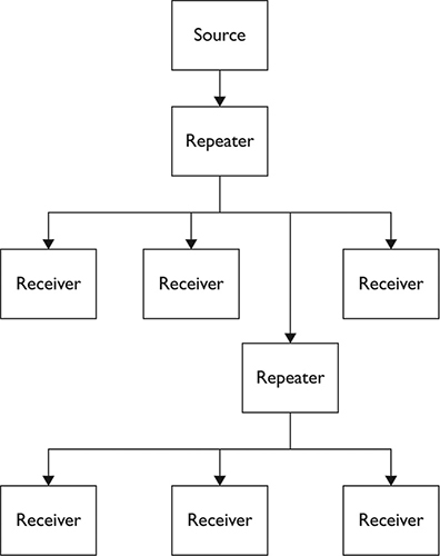
Figure 15-3 Depth of two repeater levels and device count of six in HDCP 2.x topology
Although HDCP 2.x supports up to 32 connected devices, in practice, the number of sink/display devices allowable from a single HDCP-protected media source is typically much more limited and based upon the number of keys allowed by the source.
HDCP Troubleshooting
When HDCP authentication fails to initiate correctly, there can be a range of symptoms that do not directly implicate HDCP failure as their cause. These may include an image appearing for a few seconds at the start of a session and then disappearing, a green screen, white noise, or a blank screen, any of which could be caused by a broken cable, a bad connector, or dozens of other problems.
An HDMI signal analyzer or signal generator/analyzer is one of the few tools that will let you track and analyze the HDCP negotiation process, providing you insight into where the negotiations have gone wrong and a clue as to how you might remedy that issue. If such an analyzer is not available, then the signal flow troubleshooting strategy is likely to be the most productive. Start at the source end of the signal path with a known working display device and follow the signal path, testing at each point until you find the fault.
Verifying the Video Signal Path
When verifying a video system, you first should check the wiring and cabling of the video equipment.
Once all connections have been completed, verify that the wiring methods and cable pathways are as specified in the system design. This is typically a visual inspection process because you will need to compare the technical drawings, such as a signal flow drawing, against what you discover in the installation.
As with audio system wiring, during the inspection process, you need to look for the following:
• Correctly terminated connectors. Look for defects such as bent pins or frayed shields.
• Correctly connected cables. They should be attached to terminals as indicated on your system drawings.
• Cabling in the pathways that are properly organized in the walls, raceways, and the ceiling. Also, check for proper bend radius at all junctions and pull boxes.
As you work through this, record any errors or discrepancies for immediate repair. Permanent changes that occurred during installation should be documented and submitted to the AV system engineer or system designer for updating the as-built documentation.
Signal Extenders
Due to the resistive and reactive properties of all cables, long cable runs can cause significant signal attenuation. The high-frequency components in video signals limit the effective length of DVI, HDMI, and DisplayPort cable runs to a theoretical maximum of 5 meters (16 feet), which is often not sufficient for a professional AV system. One of the solutions to this problem is the use of an extender technology, which not only reaches farther than a direct video connection but is often cheaper than a long run of quality digital video cable.
Passive Extenders
Passive extenders (see Figure 15-4) generally use balun technology to interface between the digital video cable and one or two twisted-pair network cables such as Cat 6+ to extend the video signal over distances up to about 50 meters (165 feet). Short for balanced-to-unbalanced, a balun is a transformer used to connect between a balanced circuit and an unbalanced circuit. In an extender application, one balun is required at the point of connection between the video signal and the twisted-pair network cable, and a second balun is required at the far end of the twisted-pair extension cable to match the video signal to the receiving device.

Figure 15-4 A pair of HDMI baluns
Some extension systems use a single twisted-pair network cable, while others use two cables. As baluns are less than 100 percent efficient and there is signal attenuation in the extension cables, the specified distance limitations of extension systems must be observed. It is important that the extender devices at each end of the extension system are of completely compatible make and model, as there is no standard for pinouts between manufacturers and product ranges.
Active Extenders
Active extenders contain processing circuitry to boost and regenerate the video signals before transmission down the extension line and to regenerate them again at the receiving end. This enables active extenders to operate over greater distances than passive extenders. These extenders may use one or two twisted-pair network cables (Cat 6+) or one or two optical fiber cables as their extension medium. HDMI and DisplayPort signals may easily be extended for distances up to about 100 meters (330 feet) with wired extensions and up to 30km (19 miles) with fiber-optic extensions.
Active extenders require power to drive the processing electronics in both the transmitting and receiving devices. Some wire-connected systems send power down the cable(s) from the transmitter to the receiver, while others, including fiber-based systems, require a power supply at both ends. As with passive extenders, it is important that the transmitters and receivers are of completely compatible make and model, as there is no standard for pinouts and signal levels between manufacturers and product ranges. HDBaseT is a widely used active extender technology, with a full ecosystem of HDMI extension and distribution devices available.
It is also a common practice in event, large venue, and broadcast applications to use standard video conversion devices to convert HDMI or DisplayPort to XX-SDI, run the XX-SDI over coax or fiber to the destination, and then convert the XX-SDI back to HDMI or DisplayPort for display. This is a useful solution for locally originating content, but replay of copy-protected material can be problematic, as XX-SDI does not support HDCP.
Network Extenders
As discussed in Chapter 12, a range of AV over IP technologies can be used to extend video signal delivery to any point on a TCP/IP network.
![]() NOTE Active extenders reclock the signal and output a duplicate of the original signal. Passive extenders change the physical medium but do not reclock the signal.
NOTE Active extenders reclock the signal and output a duplicate of the original signal. Passive extenders change the physical medium but do not reclock the signal.
Verifying Video Sources
In Chapter 10, you learned about the installation of video components, including video cameras and projectors. After the installation, you will need to fine-tune camera adjustments and complete projector calibration.
The location, intensity, and shadow quality of light sources in the picture area play a major part in the quality of the images picked up by cameras. When low-contrast lighting is used, images often look washed out and flat, while appropriately designed lighting will create images with contrast, dimension, and good exposure. The design of the lighting for video camera image capture is an integral part of any AV system design, and checking alignment, light levels, coverage, color temperature, color rendering, and contrast ratios should form part of the verification of the installation. The system design documents should include details of all lighting alignment parameters. It is quite common for a lighting designer, gaffer, director of photography, or lighting technician to be brought in for final alignments and level setting before system handover on projects with many luminaires and complex requirements.
Camera Adjustments
Clients tend to use cameras for videoconferences and to record and stream activities in their facilities. Similar to other AV devices, cameras should be set up for the environment in which they operate. Sometimes, cameras are connected and powered on, and that is the extent of the setup. However, a professional AV installer should make some standard adjustments to a camera to ensure that the images produced are of adequate quality.
Focus
The focus adjustment allows the camera to deliver a sharp, clearly visible image of the subject. To set the focus:
1. Have a subject stand in the general location where the camera will normally be capturing images.
2. Zoom the lens in tightly to the subject and adjust the main focus until the subject image appears sharp and crisp. A focus chart (see Figure 15-5) can make the process easier; the contrasting black and white sections allow for very accurate focusing.

Figure 15-5 A sample focus chart
3. Zoom back out to frame the shot for the best coverage.
Back-focus
Lenses must stay in focus as they are zoomed from wide-angle shots to narrow fields of view. Adjusting the back-focus on the lens will keep zoomed-out images focused. To adjust back-focus:
1. Locate the back-focus setting on the camera lens. If the camera has this setting, it will likely be a manual, hardware-dependent adjustment near the focus setting.
2. At the target area, zoom into the previously used focus chart, and focus as before.
3. Zoom all the way out and adjust the back-focus until the shot is again in focus.
Repeat this process until the lens stays in focus throughout its zoom range. If possible, lock the setting in place.
Pan, Tilt, Zoom, and Focus Presets
In system designs that include preset scenes or setups for cameras with remote robotic pan/tilt/zoom (PTZ) capabilities, each preset should be set up as specified in the design and the preset labeled with the name, such as “wide shot,” “presenter closeup,” “white board,” or “full stage,” as indicated in the design documents. Fixed-position cameras with remote zoom and focus preset capabilities should be set up in a similar way.
Some more advanced robotic camera systems may include capabilities for remote dolly/pedestal position, camera elevation, and live moves. These systems will generally be set up in collaboration with the end user during system training prior to sign-off.
Iris Settings (Exposure)
The iris in the camera’s lens controls how much light passes through the lens to reach the camera’s imaging device(s). Some adjustment to the iris will usually be required to correctly set the exposure of the image. If light levels change in the area covered by the camera, the aperture (opening) of the iris will require adjustment to maintain the correct exposure of the image. This adjustment is generally found on the body of the camera, as shown in Figure 15-6.
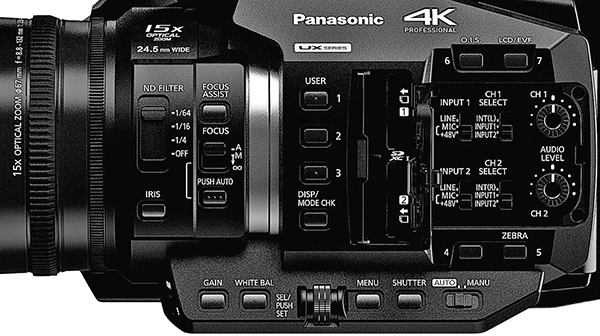
Figure 15-6 Typical controls on a professional AV camera. Courtesy of Panasonic Corporation.
The automatic iris adjustment found on many AV cameras adjusts the aperture of the iris based on the output of the camera’s image pickup device(s). Auto-iris responses may be based on the light falling on the center of the pickup (center weighted) or on the average of the light across the entire pickup area. Some camera’s auto-iris systems can be switched between several exposure modes. Most lenses will also have a manually operated iris mode, which allows an operator, either local or remote, to set the lens aperture for the desired exposure.
There is a strong interaction in the exposure of an image between the level of light on the subject of the image and the level of light on the background behind the subject (often a wall):
• If the subject is substantially brighter than the background, it is possible for the auto iris to expose the subject correctly, while the background will be less prominent.
• If the subject is much darker than the background, the auto-iris systems may expose for the level of the background and leave the subject underexposed. However, if the auto-iris system is center-weighted, it may instead expose the central subject correctly and overexpose the background. Neither of these results are likely to be satisfactory pictures.
• If the subject and the background are of similar brightness, the auto-iris system will be able to get a good exposure of the subject, but the image may lack sufficient contrast to emphasize the subject and allow it to stand out clearly from the background.
If the system design includes adequate lighting control, you will be able to expose a camera with an auto iris using the following simple procedure.
With the background lighting at its minimum level, set the subject lighting (including fill lighting and backlighting) at close to maximum intensity, and allow the auto iris to expose the camera. Now, adjust the level of the background lighting to make the background visible, but not dominant, in the image. If there is no simple dimming control, it is possible to adjust the intensity of the background lighting by switching some of it off or on or by inserting neutral density filters/meshes or diffusion material in the luminaires illuminating the background.
The balance between subject and background lighting for a good exposure will vary substantially depending on the color and brightness of the subject material. If the subject is a person, the reflectivity of their skin will greatly affect the balance. You will most likely have to adjust the lighting to account for significant changes between darker and lighter skin tones of subjects. If the lighting control system has preset level memory, it is advisable to set up a number of lighting states to accommodate the range of skin tones that may be present in the subject area.
Backlight Adjustment
Some cameras have a backlight adjustment mode, which surprisingly has nothing to do with the lighting focused on the back and edges of a subject to give separation from the background. The backlight adjustment is a compensation control for when a subject is seen against a bright background, such as a daylit window, which usually tricks the auto-iris system into underexposing the less-lit subject.
When activated, the backlight adjustment attempts to compensate for the over-bright background by increasing the aperture of the camera above the auto-iris setting to bring the subject up to a better exposure. This inevitably overexposes the background in the process of solving the subject’s exposure. Use of the backlight adjustment is, at best, a temporary measure to be used under duress. The solution to the problem is to improve the balance of light in the image by either reducing the light in the background (such as closing the curtain or blind over the window) or increasing the light level on the subject. Light-reducing window tinting can be used as a permanent solution to allow a subject to be seen against a brightly daylit exterior.
Automatic Gain Control
In situations where insufficient light is available to properly expose an image, it is possible to lift the brightness of the image by increasing the output of the camera’s imaging device(s) via the video gain control functions. As with any amplification process, increasing gain also increases the noise in the signal, which results in random sparkles in the video output. Engaging the auto gain control (AGC), if available, will usually result in images that are of sufficient brightness, but will often be quite noisy. The best solution is to make sure that the subject is in an adequately lit area, which may be as simple as moving the subject into an existing pool of light or swinging a couple of lights around to cover the subject area.
Shutter Adjustments
The camera’s shutter system controls the amount of light that the imaging system must process. In some cameras this is achieved by varying the size or speed of an actual rotating mechanical shutter that sits in the optical train before the imaging device(s). In other cameras the shutter control is a setting that varies the time between successive readings of the data from the imaging device(s). If a lot of light is entering the camera from a very bright scene, an automatic shutter system will reduce the amount of time the shutter is open, which may cause any fast movements in the scene to appear stuttered or jerky. The best solution to jerkiness caused by the shutter is to use some means other than the shutter to reduce the exposure of the imaging device(s). These solutions include reducing image gain, inserting a neutral density filter, or possibly closing down the iris.
White Balancing
Many cameras have an automatic white balance function. This circuit looks for bright objects in the image, assumes that they are white, and adjusts the color levels in the camera’s output to produce a white signal for those bright objects. It is therefore critical that all automatic white balancing is performed using a matte white reference object, such as a piece of white cardstock or paper, illuminated by the same lighting as the subject. If the automatic white balance feature is off, manual white balancing is required. This is often performed using a grayscale chart to fine-tune the color balance across the camera’s full dynamic range.
To automatically white-balance a video camera:
1. Place a large piece of white paper at the object location in the lighting that will be used for the subject.
2. Zoom into the white paper until it fills as much of the image as possible.
3. Press the white balance button. This will set the color reference levels for the current lighting conditions.
An automatic white balance is the best attempt the camera’s electronics can make under limited conditions, so it is unwise to expect that two cameras capturing images of the same object will completely match, even if they are of the same model and have the same lens. Where color matching between multiple cameras is important, expert human intervention is usually required.
Some cameras have a number of preset color balance settings that may be selected to accommodate known color temperature conditions.
Verifying Display Components
Displays should be set up and adjusted to produce the best image based on the environment in which they are to be viewed. The viewing environment can have a major effect on the quality of the displayed image. Viewing a movie in the theater, watching a presentation in a boardroom, viewing the IMAG on a live event, and viewing digital signage in bright daylight are very different viewing experiences.
Display setup requires knowledge of signal generators and the purposes of common test patterns. A knowledgeable technician can make the necessary adjustments based on the viewing environment.
Identify Display Parameters
The first step is to identify the parameters of the display device, which could be a projector, an LED screen, or a flat-panel display. Next, determine the input signal types that will be used on the display. The signal will probably be HDMI, SDI, or DisplayPort, although DVI and RGBHV may still occasionally be used in existing systems.
Determine the aspect ratio of the displayed image. The most common ratio is 16:9, although other ratios may be used in cinematic; video-wall; and multi-panel, multi-module, or multi-projector systems. This information for each display device may be in the owner’s manual, or it can be calculated by dividing the width by the height of the displayed image. As a guide, a ratio of width to height of 1.77:1 is equivalent to 16:9.
It is possible to display an image that was designed for a legacy 4:3 display on a 16:9 display, but depending on the display system settings, the image will be either horizontally stretched to fit, or have vertical black bars on either side of the image. Similarly, images intended for wide screen (2.39:1) cinematic display will usually display with horizontal black bars at top and bottom. It is usually preferrable to set up the display to show the entire image unstretched with black bars than with the image either cropped or distorted by stretching. If these settings are not defined in the system design documents, you should consult with the client or end user.
Set Contrast
The test pattern shown in Figure 15-7 is used to set contrast. The white rectangle in the center is super white (step 255), or the brightest item on the screen. The two very black rectangles beside it are super black (step 0), and the black background that surrounds the white and blacker rectangles is normal video black (step 16). The goal is to strike a balance between all the shades in the image. Make adjustments until all the bars are clearly distinct and visible. Ensure the white bars look white and the black bars look black. If the display’s grayscale transfer function (gamma) is set correctly, the bars should appear in even, gradual steps.

Figure 15-7 Test pattern to set contrast
If the black sections of the image are too dark, increase the brightness control. If the image sections are too bright, increase the contrast. It may take several adjustments to balance the image and ensure that all variations of white and gray can be clearly seen.
The procedure for adjusting brightness and contrast is as follows:
1. Display a grayscale test pattern.
2. Adjust the contrast level down and then increase the level while watching the white rectangle in the center of the screen. Adjust up until the white does not get any whiter.
3. Adjust brightness until you cannot see any difference between black and super black.
4. Repeat the adjustments until both settings are achieved.
Once complete, the gray bars should gradually increase/decrease in value in a linear fashion. Repeat these steps until all bars appear in even, gradual steps.
Set Chroma Level
Color bars are test patterns that provide a standard image for color alignment of displays. They can be used to set a display’s chroma level (color saturation) and, where present, hue shift. Hue shift control is generally only found on systems that display images in the US NTSC format, which is prone to color phase errors.
Adjust the display for accurate monochrome brightness and contrast before color adjustments.
A commonly used test pattern is the HD Society of Motion Picture and Television Engineers (SMPTE) version. Alternatively, you may come across the Association of Radio Industries and Businesses (ARIB) version. You can use these interchangeably, and the process for using them is almost identical.
Check Appendix D for the link to the AVIXA video library, which includes a video explaining the process of setting the contrast, brightness, and chroma.
Image System Contrast
Image quality can be assessed using criteria such as contrast, luminance, color rendition, resolution, video motion rendition, image uniformity, and even how glossy a screen is. However, contrast remains the fundamental metric to determine image quality. Taking the viewing environment into consideration, the difference between system black and the brightest possible image is the system contrast ratio.
AVIXA developed the ANSI standard ANSI/AVIXA 3M-2011, Projected Image System Contrast Ratio, which set out how to measure contrast ratios and what contrast ratios are suitable for different viewing requirements. That standard has since been updated and revised and will shortly be replaced by ANSI/AVIXA V201.01:202X Image System Contrast Ratio (ISCR), a standard that extends beyond projection to cover system contrast for viewing all images, including both projection and direct-viewed displays. The complete standards are available from the Standards section of the AVIXA website at www.avixa.org, but here is a brief summary of the four viewing requirement categories and their required minimum contrast ratios:
• Passive viewing is where the content does not require assimilation and retention of detail, but the general intent is to be understood (e.g., noncritical or informal viewing of video and data). This requires a minimum contrast ratio of 7:1.
• Basic decision-making (BDM) requires that a viewer can make decisions from the displayed image but that comprehending the informational content is not dependent upon being able to resolve every element detail (e.g., information displays, presentations containing detailed images, classrooms, boardrooms, multipurpose rooms, product illustrations). This requires a minimum contrast ratio of 15:1.
• Analytical decision-making (ADM) is where the viewer is fully analytically engaged with making decisions based on the details of the content right down to the pixel level (e.g., medical imaging, architectural/engineering drawings, fine arts, forensic evidence, photographic image inspection). This requires a minimum contrast ratio of 50:1.
• Full-motion video is where the viewer is able to discern key elements present in the full-motion video, including detail provided by the cinematographer or videographer necessary to support the story line and intent (e.g., home theater, business screening room, live event production, broadcast postproduction). This requires a minimum contrast ratio of 80:1.
The standards include a simple measurement procedure to verify that the system conforms to the desired contrast ratio of the viewing task. First, you must identify the five measurement locations, as shown in Figure 15-8. The five locations are to be recorded on a viewing area plan.

Figure 15-8 Contrast ratio should be measured from five locations within the viewing area
• Viewing location 1 Viewing location closest to the image and farthest to the left in the plan view, as indicated in Figure 15-8.
• Viewing location 2 Viewing location closest to the screen and farthest to the right in the plan view, as indicated in Figure 15-8.
• Viewing location 3 Viewing location at the central point of viewing locations 1, 2, 4, and 5, as indicated in Figure 15-8. In the case where this central viewing location is obstructed (such as by a conference table), the measurement location will be the first available viewing location on the screen center line behind the obstruction.
• Viewing location 4 Viewing location farthest from the screen and farthest to the left in the plan view, as indicated in Figure 15-8.
• Viewing location 5 Viewing location farthest from the screen and farthest to the right in the plan view, as indicated in Figure 15-8.
After you have identified the viewing locations, measure the contrast ratio of the system using a 16-zone black-and-white checkerboard (intra-frame) pattern, as shown in Figure 15-9. You will also need a luminance meter or spot photometer with up-to-date calibration.

Figure 15-9 Checkerboard pattern used to measure contrast ratio
The procedure for verifying image contrast ratio is as follows:
1. Display a 16-zone black-and-white checkerboard test pattern on the projection screen, as illustrated in Figure 15-9, under conditions that represent the actual viewing environment.
2. From the first measurement position identified on the viewing area plan (viewing location 1), measure and record the luminance values at the center of each of the eight white rectangles.
3. From the same measurement position, measure and record the luminance values at the center of each of the eight black rectangles.
4. Calculate the average of the eight white measurements and the average of the eight black measurements.
5. Divide the resulting average white value by the average black value to obtain the contrast ratio at that measurement position.
6. Repeat the contrast measurement procedure at each of the five measurement positions identified on the viewing area plan.
7. Record the resulting contrast ratios for each of the measurement positions on the viewing area plan.
Contrast ratio = average maximum luminance / average minimum luminance
If the contrast ratio meets or exceeds the minimum laid out in the ISCR standard at all five viewing locations, then the system conforms to the standard. If the contrast ratio of one but no more than four measurement (viewing) locations falls below the required ratio for the identified viewing category by no more than 10 percent, the system partially conforms. If the contrast ratio at any one of the measured locations falls below the identified viewing category by more than 10 percent, the system fails to conform to the ISCR standard.
Audio/Video Sync
In many AV systems, the audio and video signals may take significantly different paths to get from the source to the point at which the user will experience them, such as in a seat within a venue, at a remote location, or distribution of recorded program material. The audio and video signals may also undergo very different numbers of processing steps, each with their own inherent latency.
In systems where associated video and audio signals may be transported or processed separately and are then subsequently combined for transmission or display, one of those signals could be delayed more than the other, creating synchronization errors sometimes known as lip-sync errors. These errors are typically corrected by applying delay to the least delayed signal so that it aligns with the most delayed signal. For a good user experience, the signals should arrive in synchronization at the point at which the user will experience them, regardless of whether that point is local or remote.
Sync Standards
As part of the metric selection process, the following documentation should be referred to in order of precedence to define the metric required for testing:
• ITU-R BT.1359-1
• EBU Recommendation R37
• ATSC IS-19
In the absence of defined requirements in the project documentation, the recommended maximum interval by which the audio should lead the video is 40 milliseconds and by which audio should lag behind the video is 60 milliseconds throughout an entire signal chain. This equates to approximately two or three frames on video systems.
For television applications, the recommended maximum synchronization error is audio leading by 15 milliseconds or lagging by 45 milliseconds.
A “blip-and-flash” test is a common method for measuring the synchronization of audio and video signals. A test signal consisting of one full frame of white video, accompanied by an audio tone of the same time length, is required. An alternative signal may be an image changing from full-frame white to full-frame black at regular intervals, with each change accompanied by a brief click or tone burst. In the absence of an appropriate signal generator, this can be produced by a computer running a slideshow. The signal at the point of reception can then be analyzed using a dual-channel digital storage oscilloscope to record the timings at which the audio and video signals are received.
If the sync alignment is not being measured, then a subjective reception test using the same test signal may be used, in addition to replaying video material that clearly depicts a person, such as a news presenter, speaking directly to camera. The subjective effect of any delay can then be evaluated for a pass/fail assessment.
Tests should be undertaken at the inputs of recording devices, at the inputs to transmission devices such as videoconferencing codecs and broadcast circuits, and locally within a presentation space at both near-screen and farthest-viewer positions.
Verifying Audio/Video Sync
After the AV system has been installed and all recording devices, presentation equipment, and link equipment/circuits are operational, the procedure for measuring the time alignment of the audio and video signals is as follows:
1. Set up a blip-and-flash source.
2. Measure delay (synchronization error) between audio and video at nearest and farthest viewer positions within the room.
3. Measure delay at inputs to all recording devices.
4. Measure delay at inputs to all transmission devices, such as codecs, network streaming interfaces, and broadcast circuits.
5. Note if the measured delay is within the specifications as stated in the project documentation or within +15 to –45 milliseconds (audio/video) in the absence of other information.
Alternative subjective tests may be undertaken using source video with no synchronization error, where a person is seen speaking. Validate subjective synchronization delay at locations listed earlier.
Correcting Audio/Video Sync Errors
Downstream video processing can cause delay. Some displays have built-in video processors, which, when used in conjunction with audio processors, scalers, and other processors, will cause delay in the signal.
Unfortunately, there is no clear way to predict how much, if any, delay will occur in an AV system. The latency introduced depends on the digital signal processors within the system, and the specific amount varies by manufacturer and device type. In some cases, you may be able to depend on the HDMI lip-sync feature, which will automatically compensate for delays in the video signal. In these cases, EDID can be used as a tool for correcting the sync issues. HDMI uses EDID to communicate delay information to upstream devices. During negotiation it will measure the delay introduced and send that information to the sink for automatic correction. This may be sufficient for systems with a single display, but with systems that involve multiple displays, when EDID detects different devices with different delay values, it is unlikely to be able to derive a single delay correction that will work for all sink devices.
In these cases, the integrator can manually introduce delay into an audio distribution system. Delay is a function typically found within digital signal processors (DSPs), switchers, or as a stand-alone, dedicated device.
Delay allows you to extract the audio at the beginning of the signal chain and send it right to the infrastructure. If you are responsible for selecting DSPs for a system, you should consider including a DSP that has the capacity to compensate for delay. Then, if you do encounter this problem, you can compensate for it by using a blip-and-flash test reel and adjusting the delay until the signals are back in sync.
Video Verification Checklists
The Video System Performance Verification Items and the Audio/Video System Performance Verification Items from the ANSI/AVIXA 10:2013 Audio Systems Performance Verification standard are listed here in Figure 15-10 and Figure 15-11, followed by a description of each list item. You may find some of these verification processes applicable to an installation you are undertaking, or you may find some processes that can form the basis of your own verification procedures. Verifying the performance of video systems according to established standards will help you assure overall system performance.

Figure 15-10 Video performance verification items from the ANSI/AVIXA 10:2013 Standard for Audiovisual Systems Performance Verification
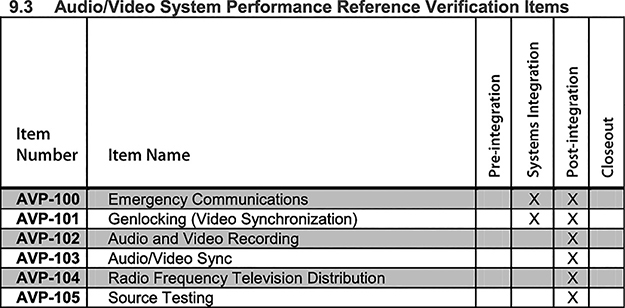
Figure 15-11 Audio/video performance verification items from the ANSI/AVIXA 10:2013 Standard for Audiovisual Systems Performance Verification
• VP-100 Verify that the EDID (Extended Display Identification Data) management plan has been implemented as defined in the project documentation.
• VP-101 Verify that the HDCP (High-bandwidth Digital Content Protection) management plan has been implemented as defined in the project documentation.
• VP-102 Verify that the combined installation of projector and screen provides a displayed image that is correctly aligned to the active projection screen surface without misalignment unless an alternative condition is specified in the project documentation.
• VP-103 Verify that all displayed images do not have pixel failures (bright or dead pixels) that exceed the requirements of the project documentation or the manufacturer’s specifications. This verification item shall require a metric to be verified.
• VP-104 Verify that all displayed images are correctly focused, have the correct image geometry and are free from distortion (e.g., stretching, keystone, barrel/pincushion). Any requirements for projection mapping or image shaping to unusual surfaces should be validated in accordance with the requirements of the project documentation.
• VP-105 Verify that the components of the displayed image system(s) (projection or direct-view) perform(s) as required with relation to image size, viewing angles, sight lines, viewer locations and/or any other requirements as defined in the project documentation.
• VP-106 Verify calibration of all video displays to ensure they display colors uniformly to a common reference standard as defined in the project documentation.
• VP-107 Verify that the system(s) accurately displays all resolutions required by project documentation on all displays within the system (i.e., no pixel shift, no geometric distortion, no artifacts from scaling, letterboxing, pillarboxing, or windowboxing).
• VP-108 Verify that the combined installation of projector and screen provides a display to the viewer that meets the requirements of the project documentation. This verification item shall require a metric to be verified.
• VP-109 Verify that the system conforms to the appropriate viewing category as defined in the project documentation. The testing methodology in ANSI/AVIXA V201.01:202X (and 3M-2011) shall be used. The projected image contrast ratio shall be measured for all projected images within the system. This verification item shall require a metric to be verified.
• VP-110 Verify that all video routes are tested from endpoint to endpoint via the appropriate midpoint(s) for operation and routing required by the project documentation.
• VP-111 Verify that cameras, lenses, and pan/tilt systems operate as defined in the project documentation. Inspect the camera image through the full lens operation.
• AVP-100 Verify that emergency communications systems properly receive inputs and information from other systems (including but not limited to life safety systems, security systems, and weather notifications), deliver appropriate notifications to target audiences, comply with regulatory requirements, and adhere to requirements defined in the project documentation.
• AVP-101 Verify that the video synchronization of the system is performing as defined in the project documentation.
• AVP-102 Verify that audio and video signals are being routed to the recording device(s) and that the recording device(s) is operating correctly, as defined in the project documentation.
• AVP-103 Verify that audio/video synchronization is maintained to ensure the proper time alignment of signals during playback at the point of user experience or transmission as defined in the project documentation. This verification item should require a metric to be verified.
• AVP-104 Verify that the radio frequency and satellite intermediate frequency distribution systems provide all services to all endpoints as defined in the project documentation. This verification item shall require a metric to be verified.
• AVP-105 Verify that the signal produced by a source typical of what will be used in normal operation of the system is routed through the system to applicable endpoints and produces the performance as defined in the project documentation. A test generator shall not be used for this verification item.
Chapter Review
Verification that video components and the overall AV system perform as per specification is an important deliverable in an installation project.
Upon completion of this chapter, you should be able to do the following:
• Identify and address problems in the video system
• Identify HDCP concerns
• Verify that an AV system has an EDID strategy
After you ensure that the AV system you have installed works as expected, you are ready to perform system closeout, which you will learn about in Chapter 16.
Review Questions
The following questions are based on the content covered in this chapter and are intended to help reinforce the knowledge you have assimilated. These questions are similar to the questions presented on the CTS-I exam. See Appendix E for more information on how to access the free online sample questions.
1. Which of the following provides a method of ensuring the best image quality between source and sink/display?
A. HDCP
B. EDID
C. HDMI
D. Hot plug
2. During the handshake process, data from the EDID table is sent to _____.
A. source devices
B. sink devices
3. Which of the following information does the EDID packet contain? (Choose all that apply.)
A. Timing for audio and video sync
B. Display parameters
C. Extension flags
D. Color characteristics
4. What are possible reasons for no picture on the screen? (Choose all that apply.)
A. The display device is not plugged in.
B. The source device is unable to read EDID data packets.
C. The hot plug pin is unable to detect a display device.
D. A switcher is intercepting the hot plug detection.
5. Which of the following is a form of encryption to protect copyrighted content?
A. VESA
B. EDID
C. HDMI
D. HDCP
6. Which of the following are HDCP authentication steps? (Choose all that apply.)
A. Locality check
B. Key exchange
C. Audio and video sync check
D. Session exchange
7. Which of the following does HDCP 2.x support? (Choose all that apply.)
A. 128 connected devices for each transmitter
B. 4 layers or repeater levels for each transmitter
C. 7 layers or repeater levels for each transmitter
D. 32 connected devices for each transmitter
8. HDCP is capable of working over which of the following interfaces? (Choose all that apply.)
A. DisplayPort
B. HDMI
C. MHL
D. HDBaseT
9. According to the ANSI/AVIXA V201.01:202X Image System Contrast Ratio (ISCR) standard, what is the minimum contrast ratio of basic decision-making tasks?
A. 7:1
B. 15:1
C. 50:1
D. 80:1
10. What type of video is best used to verify audio/video synchronization?
A. Landscapes with orchestra music
B. News anchors speaking
C. Team sports
D. A blip-and-flash test video
Answers
1. B. Extended display identification data (EDID) is a method of ensuring the best image quality between video source and display.
2. A. Data from the EDID table in the display device is sent to the source device.
3. A, B, C, D. EDID packets contain timing for audio/video sync, display parameters, extension flags, and color characteristics.
4. A, B, C, D. If the display device is not plugged in, the source is unable to read EDID data packets, the hot plug pin is unable to detect a display advice, or the switcher intercepts the hot plug detection, then a display device may not show an image on the screen.
5. D. High-bandwidth digital content protection (HDCP).
6. A, B, D. Locality check, key exchange, and session exchange are HDCP authentication steps.
7. B, D. HDCP 2.x supports up to 32 connected devices for each transmitter and a maximum of four repeater levels for each transmitter.
8. A, B, C, D. HDCP is capable of working over all of these video interfaces.
9. B. 15:1 is the minimum contrast ratio for images used in basic decision-making tasks.
10. D. A blip-and-flash test will reveal audio or video latency.