
 Network Fundamentals
In this chapter, you will learn how to
![]() Identify the basic network architectures
Identify the basic network architectures
![]() Examine segregation, segmentation, and isolation with respect to network architectures
Examine segregation, segmentation, and isolation with respect to network architectures
![]() Classify security zones
Classify security zones
![]() Explain routing and address translation
Explain routing and address translation
![]() Examine the Internet Protocol in depth
Examine the Internet Protocol in depth
![]() Define the basic network protocols
Define the basic network protocols
![]() Explore additional elements of networking
Explore additional elements of networking
By the simplest definition in the data world, a network is a means to connect two or more computers together for the purposes of sharing information. The term network has different meanings depending on the context and usage. A network can be a group of friends and associates, a series of interconnected tunnels, or, from a computer-oriented perspective, a collection of interconnected devices. Network sizes and shapes vary drastically, ranging from two personal computers connected with a crossover cable or wireless router all the way up to the Internet, encircling the globe and linking together untold numbers of individual, distributed systems. Though data networks vary widely in size and scope, they are generally defined in terms of their architecture, topology, and protocols.
 Network Architectures
Every network has an architecture—whether by design or by accident. Defining or describing a specific network’s architecture involves identifying the network’s physical configuration, logical operation, structure, procedures, data formats, protocols, and other components. For the sake of simplicity and categorization, people tend to divide network architectures into two main categories: LANs and WANs. A local area network (LAN) typically is smaller in terms of size and geographic coverage and consists of two or more connected devices. Home networks and most small office networks can be classified as LANs. A wide area network (WAN) tends to be larger, covering more geographic area, and consists of two or more systems in geographically separated areas connected by any of a variety of methods such as leased lines, radio waves, satellite relays, microwaves, or even dial-up connections. With the advent of wireless networking as well as optical and cellular technology, the lines between LAN and WAN models may seem to blur, but in practice the two categories merge seamlessly into a single network entity. For example, most corporations have multiple LANs within each office location that all connect to a WAN that provides intercompany connectivity. Figure 9.1 shows an example of a corporate network. Each office location will typically have one or more LANs, which are connected to the other offices and the company headquarters through a corporate WAN.
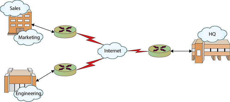
• Figure 9.1 Corporate WAN connecting multiple offices
![]()
A LAN is a local area network—an office building, home network, and so on. A WAN is a wide area network—a corporate network connecting offices in Dallas, New York, and San Jose, for example.
Over time, as networks have grown, diversified, and multiplied, the line between LAN and WAN has become blurred. To better describe emerging, specialized network structures, new terms have been coined to classify networks based on size and use:
![]() Campus area network (CAN) A network connecting any number of buildings in an office or university complex (also referred to as a campus wide area network).
Campus area network (CAN) A network connecting any number of buildings in an office or university complex (also referred to as a campus wide area network).
![]() Intranet A “private” network that is accessible only to authorized users. Many large corporations host an intranet to facilitate information sharing within their organization.
Intranet A “private” network that is accessible only to authorized users. Many large corporations host an intranet to facilitate information sharing within their organization.
![]() Internet The “global network” connecting hundreds of millions of systems and users.
Internet The “global network” connecting hundreds of millions of systems and users.
![]() Metropolitan area network (MAN) A network designed for a specific geographic locality such as a town or a city.
Metropolitan area network (MAN) A network designed for a specific geographic locality such as a town or a city.
![]() Storage area network (SAN) A high-speed network connecting a variety of storage devices such as tape systems, RAID arrays, optical drives, file servers, and others.
Storage area network (SAN) A high-speed network connecting a variety of storage devices such as tape systems, RAID arrays, optical drives, file servers, and others.
![]() Virtual local area network (VLAN) A logical network allowing systems on different physical networks to interact as if they were connected to the same physical network.
Virtual local area network (VLAN) A logical network allowing systems on different physical networks to interact as if they were connected to the same physical network.
![]() Client/server A network in which powerful, dedicated systems called servers provide resources to individual workstations, or clients.
Client/server A network in which powerful, dedicated systems called servers provide resources to individual workstations, or clients.
![]() Peer-to-peer A network in which every system is treated as an equal, such as a home network.
Peer-to-peer A network in which every system is treated as an equal, such as a home network.
![]() Software-defined network A network where the routing and switching functions are under separate software control.
Software-defined network A network where the routing and switching functions are under separate software control.
Network Topology
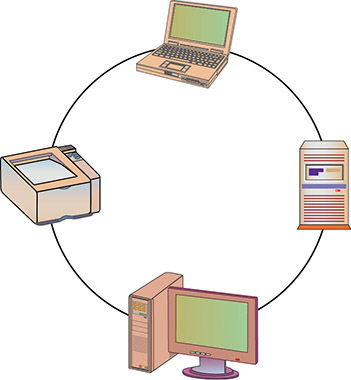
One major component of every network’s architecture is the network’s topology. Network topology is how the network components are physically or logically arranged. Terms to classify a network’s topology have been developed, often reflecting the physical layout of the network. The main classes of network topologies are star, bus, ring, and mixed:
![]() Star topology Network components are connected to a central point (see Figure 9.2).
Star topology Network components are connected to a central point (see Figure 9.2).
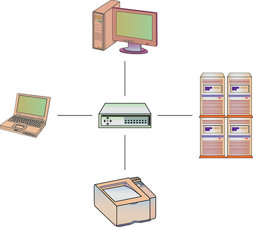
• Figure 9.2 Star topology
![]() Bus topology Network components are connected to the same cable, often called “the bus” or “the backbone” (see Figure 9.3).
Bus topology Network components are connected to the same cable, often called “the bus” or “the backbone” (see Figure 9.3).
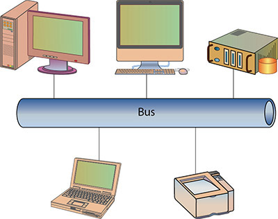
• Figure 9.3 Bus topology
![]() Ring topology Network components are connected to each other in a closed loop, with each device directly connected to two other devices (see Figure 9.4).
Ring topology Network components are connected to each other in a closed loop, with each device directly connected to two other devices (see Figure 9.4).
• Figure 9.4 Ring topology
![]() Mixed topology Larger networks, such as those inside an office complex, may use more than one topology at the same time. For example, an office complex may have a large ring topology that interconnects all the buildings in the complex. Each building may have a large bus topology to interconnect star topologies located on each floor of the building. This is called a mixed or hybrid topology (see Figure 9.5).
Mixed topology Larger networks, such as those inside an office complex, may use more than one topology at the same time. For example, an office complex may have a large ring topology that interconnects all the buildings in the complex. Each building may have a large bus topology to interconnect star topologies located on each floor of the building. This is called a mixed or hybrid topology (see Figure 9.5).

• Figure 9.5 Mixed topology
With recent advances in technology, these topology definitions often break down. While a network consisting of five computers connected to the same coaxial cable is easily classified as a bus topology, what about those same computers connected to a switch using Cat-6 cables? With a switch, each computer is connected to a central node, much like a star topology, but the backplane of the switch is essentially a shared medium. With a switch, each computer has its own exclusive connection to the switch like a star topology but has to share the switch’s communications backbone with all the other computers, much like a bus topology. To avoid this type of confusion, many people use topology definitions only to identify the physical layout of the network, focusing on how the devices are connected to the network. If we apply this line of thinking to our example, the five-computer network becomes a star topology whether we use a hub or a switch.

Wireless networks use radio waves as their medium to transmit packets, and those radio waves don’t stop at the walls of your house or your organization. Anyone within range can “see” those radio waves and attempt to either sniff your traffic or connect to your network. Encryption, MAC address filtering, and suppression of beacon frames are all security mechanisms to consider when using wireless networks. Wireless networks, because of the signal propagation, can easily assume a mesh structure.
Wireless
Wireless networking is the transmission of packetized data by means of a physical topology that does not use direct physical links. This definition can be narrowed to apply to networks that use radio waves to carry the signals over either public or private bands, instead of using standard network cabling.
The topology of a wireless network is either a hub-and-spoke model or mesh. In the hub-and-spoke model, the wireless access point is the hub and is connected to the wired network. Wireless clients then connect to this access point via wireless, forming the spokes. In most enterprises, multiple wireless access points are deployed, forming an overlapping set of radio signals allowing clients to connect to the stronger signals. With tuning and proper antenna alignment and placement of the access points, the desired areas of coverage can be achieved and interference minimized.
The other topology supported by wireless is a mesh topology. In a mesh topology, the wireless units talk directly to each other, without a central access point. This is a form of ad hoc networking and is discussed in more detail in the next section. A new breed of wireless access points has emerged on the market that combines both of these characteristics. These wireless access points talk to each other in a mesh network method, and then once they have established a background network, where at least one station is connected to the wired network, wireless clients can connect to any of the access points as if the access points were normal access points. But instead of the signal going from wireless client to access point to wired network, the signal is carried across the wireless network from access point to access point until it reaches the master device that is wired to the outside network.
Ad Hoc
An ad hoc network is one where the systems on the network direct packets to and from their source and target locations without using a central router or switch. Windows supports ad hoc networking, although it is best to keep the number of systems relatively small. A common source of ad hoc networks is in the wireless space. From Zigbee devices that form ad hoc networks to Wi-Fi Direct, a wireless ad hoc network is one where the devices talk to each other, without the benefit of an access point or a central switch to manage traffic.
Ad hoc networks have several advantages. Without the need for access points, ad hoc networks provide an easy and cheap means of direct client-to-client communication. Ad hoc wireless networks can be easy to configure and provide a simple way to communicate with nearby devices when running cable is not an option.
Ad hoc networks have disadvantages as well. In enterprise environments, managing an ad hoc network is difficult because there isn’t a central device through which all traffic flows. This means there isn’t a single place to visit for traffic stats, security implementations, and so on. This also makes monitoring ad hoc networks more difficult.
Segregation/Segmentation/Isolation
Network segmentation is where you have configured the network devices to limit traffic access across different parts of a network. This can be done to prevent access to sensitive machines, but it also aids in network traffic management. A group of database servers that never need direct connection to the Internet can be located on a network segment where routing rules will not allow direct connection from outside of the protected enclave. Dividing a network into segments generally does not take more equipment, but rather is done in how the networking equipment is configured to communicate across the defined segments. A DMZ is an example of a segment—one that is accessible from the Internet, and from the internal network, but cannot be crossed directly.
Physical Separation
Physical separation is where you have separate physical equipment for the packets to use: separate switches, separate routers, and separate cables. This is the most secure method of separating traffic, but also the most expensive. Having separate physical paths is common in enterprises in the outermost sections of the network where connections to the Internet are made. This is mostly for redundancy, but it also acts to separate the traffic.
There are contractual times where physical separation may be called for, such as in the Payment Card Industry Data Security Standards (PCI DSS). Under PCI DSS, if an organization wishes to have a set of assets be considered out of scope with respect to the security audit for card number processing systems, then it must be physically separated. Enclaves (discussed next) are an example of physical separation.
Enclaves
Modern networks, with their increasingly complex connections, result in systems where navigation can become complex between nodes. Just as a DMZ-based architecture allows for differing levels of trust, the isolation of specific pieces of the network using security rules can provide differing trust environments. Several terms are used to describe the resulting architecture from network segmentation: segregation, isolation, and enclaves. Enclaves is the most commonly used term to describe sections of a network that are logically isolated by networking protocol. The concept of breaking a network into enclaves can create areas of trust where special protections can be employed and traffic from outside the enclave is limited or properly screened before admission.
Enclaves are not diametrically opposed to the concept of a flat network structure; they are just carved-out areas, like gated neighborhoods, where one needs special credentials to enter. A variety of security mechanisms can be employed to create a secure enclave. Layer 2 addressing (subnetting) can be employed, making direct addressability an issue. Firewalls, routers, and application-level proxies can be employed to screen packets before entry or exit from the enclave. Even the people side of the system can be restricted through the use of a special set of sysadmins to manage the systems.
Enclaves are an important tool in modern secure network design. Figure 9.6 shows a network design with a standard two-firewall implementation of a DMZ. On the internal side of the network, multiple firewalls can be seen, carving off individual security enclaves, zones where the same security rules apply. Common enclaves include those for high-security databases, low-security users (call centers), public-facing kiosks, and the management interfaces to servers and network devices. Having each of these in its own zone provides for more security control. On the management layer, using a nonroutable IP address scheme for all of the interfaces prevents them from being directly accessed from the Internet.
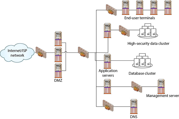
• Figure 9.6 Secure enclaves
Logical (VLAN)
A LAN is a set of devices with similar functionality and similar communication needs, typically co-located and operated off a single switch. This is the lowest level of a network hierarchy and defines the domain for certain protocols at the data link layer for communication. A virtual LAN (VLAN) is a logical implementation of a LAN and allows computers connected to different physical networks to act and communicate as if they were on the same physical network. A VLAN has many of the same characteristic attributes of a LAN and behaves much like a physical LAN but is implemented using switches and software. This very powerful technique allows significant network flexibility, scalability, and performance and allows administrators to perform network reconfigurations without having to physically relocate or re-cable systems.
![]()
A broadcast domain is a logical division of a computer network. Systems connected to a broadcast domain can communicate with each other as if they were connected to the same physical network, even when they are not.
Trunking is the process of spanning a single VLAN across multiple switches. A trunk-based connection between switches allows packets from a single VLAN to travel between switches, as shown in Figure 9.7. Two trunks are shown in the figure: VLAN 10 is implemented with one trunk, and VLAN 20 is implemented with the other. Hosts on different VLANs cannot communicate using trunks and thus are switched across the switch network. Trunks enable network administrators to set up VLANs across multiple switches with minimal effort. With a combination of trunks and VLANs, network administrators can subnet a network by user functionality without regard to host location on the network or the need to re-cable machines.
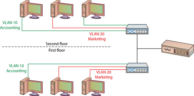
• Figure 9.7 VLANs and trunks

Physical separation requires creating two or more physical networks, each with its own servers, switches, and routers. Logical separation uses one physical network with firewalls and/or routers separating and facilitating communication between the logical networks.
Security Implications
VLANs are used to divide a single network into multiple subnets based on functionality. This permits accounting and marketing, for example, to share a switch because of proximity, yet still have separate traffic domains. The physical placement of equipment and cables is logically and programmatically separated so that adjacent ports on a switch can reference separate subnets. This prevents unauthorized use of physically close devices through separate subnets that are on the same equipment. VLANs also allow a network administrator to define a VLAN that has no users and map all of the unused ports to this VLAN (some managed switches allow administrators to simply disable unused ports as well). Then, if an unauthorized user should gain access to the equipment, that user will be unable to use unused ports, as those ports will be securely defined to nothing. Both a purpose and a security strength of VLANs is that systems on separate VLANs cannot directly communicate with each other.
Trunks and VLANs have security implications that you need to heed so that firewalls and other segmentation devices are not breached through their use. You also need to understand how to use trunks and VLANs to prevent an unauthorized user from reconfiguring them to gain undetected access to secure portions of a network.
Virtualization
Virtualization offers server isolation logically while still enabling physical hosting. Virtual machines allow you to run multiple servers on a single piece of hardware, enabling the use of more powerful machines in the enterprise at higher rates of utilization. By definition, a virtual machine provides a certain level of isolation from the underlying hardware, operating through a hypervisor layer. If a single piece of hardware has multiple virtual machines running, they are isolated from each other by the hypervisor layer as well.
Airgaps
Airgap is the term used to describe when two networks are not connected in any way except via a physical gap between them. Physically or logically, there is no direct path between them. Airgaps are considered by some to be a security measure, but this topology fails for several reasons. First, sooner or later, some form of data transfer is needed between airgapped systems. When this happens, administrators transfer files via USB-connected external media—and there no longer is an airgap.
Airgaps as a security measure fail because people can move files and information between the systems with external devices, and because of the false sense of security imparted by the airgap, these transfers are not subject to serious security checks. About the only thing that airgaps can prevent are automated connections such as reverse shells and other connections used to contact servers outside the network from within.
Zones and Conduits
The terms zones and conduits have specialized meaning in control system networks. Control systems are the computers used to control physical processes, ranging from traffic lights to refineries, manufacturing plants, critical infrastructure, and more. These networks are now being attached to enterprise networks, and this will result in the inclusion of control system network terminology into IT/network/security operations terminology. A term commonly used in control system networks is zone, which is a grouping of elements that share common security requirements. A conduit is defined as the path for the flow of data between zones.
Zones are similar to enclaves in that they have a defined set of common security requirements that differ from outside the zone. The zone is marked on a diagram, indicating the boundary between what is in and outside the zone. All data flows in or out of a zone must be via a defined conduit. The conduit allows a means to focus the security function on the data flows, ensuring the appropriate conditions are met before data enters or leaves a zone. Conduits are ideal locations for security solutions such as firewalls and network sensors. More details on network segregation in control networks is presented in Chapter 14.
Zero Trust
Traditional IT network security is based on the castle-and-moat model. In the castle-and-moat model, it is hard to obtain access from outside the network because of walls and the moat, with the only access being the gate where IDs are checked. Once you’re inside, trust is conveyed by the fact you passed the gate check. This approach has been used for years because it is simple to implement, but the problem with this approach is that once an attacker gains access to the network, they have access to everything inside.
Zero trust is a security model centered on the belief that you should not trust any request without verifying authentication and authorization. Zero trust implementations require strict identity verification for every account trying to access resources, regardless of their location. Zero trust security requires a holistic approach to security that incorporates several additional layers of defense and technologies.
Security Zones
The first aspect of security is a layered defense. Just as a castle has a moat, an outside wall, an inside wall, and even a keep, so too does a modern secure network have different layers of protection. Different zones are designed to provide layers of defense, with the outermost layers providing basic protection and the innermost layers providing the highest level of protection. A constant issue is that accessibility tends to be inversely related to level of protection, so it is more difficult to provide complete protection and unfettered access at the same time. Tradeoffs between access and security are handled through zones, with successive zones guarded by firewalls enforcing ever-increasingly strict security policies. The outermost zone is the Internet, a free area, beyond any specific controls. Between the inner, secure corporate network and the Internet is an area where machines are considered at risk. This zone has come to be called the DMZ, after its military counterpart, the demilitarized zone, where neither side has any specific controls. Once inside the inner, secure network, separate branches are frequently carved out to provide specific functionality.
DMZ
DMZ is a military term for ground separating two opposing forces, by agreement and for the purpose of acting as a buffer between the two sides. A DMZ in a computer network is used in the same way: it acts as a buffer zone between the Internet, where no controls exist, and the inner, secure network, where an organization has security policies in place (see Figure 9.8). To demarcate the zones and enforce separation, a firewall is used on each side of the DMZ. The area between these firewalls is accessible from either the inner, secure network or the Internet. Figure 9.8 illustrates these zones as caused by firewall placement. The firewalls are specifically designed to prevent access across the DMZ directly, from the Internet to the inner, secure network. It is important to note that typically only filtered Internet traffic is allowed into the DMZ. For example, an organization hosting a web server and an FTP server in its DMZ may want the public to be able to “see” those services but nothing else. In that case, the firewall may allow FTP, HTTP, and HTTPS traffic into the DMZ from the Internet and then filter out everything else.

• Figure 9.8 The DMZ and zones of trust
Special attention should be paid to the security settings of network devices placed in the DMZ, and they should be considered at all times to be at risk for compromise by unauthorized use. A common industry term, hardened operating system, applies to machines whose functionality is locked down to preserve security—unnecessary services and software are removed or disabled, functions are limited, and so on. This approach needs to be applied to the machines in the DMZ, and although it means that their functionality is limited, such precautions ensure that the machines will work properly in a less-secure environment.
Many types of servers belong in this area, including web servers that are serving content to Internet users, as well as remote access servers and external e-mail servers. In general, any server directly accessed from the outside, untrusted Internet zone needs to be in the DMZ. Other servers should not be placed in the DMZ. Domain name servers for your inner, trusted network and database servers that house corporate databases should not be accessible from the outside. Application servers, file servers, print servers—all of the standard servers used in the trusted network—should be behind both firewalls and the routers and switches used to connect these machines.
The idea behind the use of the DMZ topology is to provide publicly visible services without allowing untrusted users access to your internal network. If the outside user makes a request for a resource from the trusted network, such as a data element from an internal database that is accessed via a publicly visible web page in the DMZ, then this request needs to follow this scenario:
1. A user from the untrusted network (the Internet) requests data via a web page from a web server in the DMZ.
2. The web server in the DMZ requests the data from the application server, which can be in the DMZ or in the inner, trusted network.
3. The application server requests the data from the database server in the trusted network.
4. The database server returns the data to the requesting application server.
5. The application server returns the data to the requesting web server.
6. The web server returns the data to the requesting user from the untrusted network.
DMZs (CompTIA now refers to them as screened subnets) act as a buffer zone between unprotected areas of a network (the Internet) and protected areas (sensitive company data stores), allowing for the monitoring and regulation of traffic between these two zones.
This separation accomplishes two specific, independent tasks. First, the user is separated from the request for data on a secure network. By having intermediaries do the requesting, this layered approach allows significant security levels to be enforced. Users do not have direct access or control over their requests, and this filtering process can put controls in place. Second, scalability is more easily realized. The multiple-server solution can be made to be very scalable, literally to millions of users, without slowing down any particular layer.
Internet
The Internet is a worldwide connection of networks and is used to transport e-mail, files, financial records, remote access—you name it—from one network to another. The Internet is not a single network but a series of interconnected networks that allows protocols to operate and enables data to flow across it. This means that even if your network doesn’t have direct contact with a resource, as long as a neighbor, or a neighbor’s neighbor, and so on, can get there, so can you. This large web allows users almost infinite ability to communicate between systems.
Because everything and everyone can access this interconnected web and it is outside of your control and ability to enforce security policies, the Internet should be considered an untrusted network. A firewall should exist at any connection between your trusted network and the Internet. This is not to imply that the Internet is a bad thing—it is a great resource for all networks and adds significant functionality to our computing environments.
The term World Wide Web (WWW) is frequently used synonymously to represent the Internet, but the WWW is actually just one set of services available via the Internet. WWW or “the Web” is more specifically the Hypertext Transfer Protocol–based services that are made available over the Internet. This can include a variety of actual services and content, including text files, pictures, streaming audio and video, and even viruses and worms.
East-West Traffic
Data flows in an enterprise can be described in patterns, such as north-south and east-west. Data flowing in to and out of a data center or enterprise is called north-south traffic. East-west traffic is the data flow pattern between devices within a portion of the enterprise (that is, between functionally related boxes to support north-south traffic). The levels of east-west traffic are important to network engineers, as the networking infrastructure must be able to sustain operational loads.
![]()
East-west traffic refers to network data flows within an enterprise network. North-south traffic refers to data flowing between the enterprise network or data center and the outside of the network.
Intranet
An intranet describes a network that has the same functionality as the Internet for users but lies completely inside the trusted area of a network and is under the security control of the system and network administrators. Typically referred to as campus or corporate networks, intranets are used every day in companies around the world. An intranet allows a developer and a user the full set of protocols—HTTP(S), FTP(S), instant messaging, and so on—that is offered on the Internet, but with the added advantage of trust from the network security. Content on intranet web servers is not available over the Internet to untrusted users. This layer of security offers a significant amount of control and regulation, allowing users to fulfill business functionality while security is ensured.
Two methods can be used to make information available to outside users: Duplication of information onto machines in the DMZ can make it available to other users. Proper security checks and controls should be made prior to duplicating the material to ensure security policies concerning specific data availability are being followed. Alternatively, extranets (discussed in the next section) can be used to publish material to trusted partners.
![]()
An intranet is a private, internal network that uses common network technologies—HTTP(S), FTP(S), and so on—to share information and provide resources to organizational users.
Should users inside the intranet require access to information from the Internet, a proxy server can be used to mask the requestor’s location. This helps secure the intranet from outside mapping of its actual topology. All Internet requests go to the proxy server. If a request passes filtering requirements, the proxy server, assuming it is also a cache server, looks in its local cache of previously downloaded web pages. If it finds the page in its cache, it returns the page to the requestor without needing to send the request to the Internet. If the page is not in the cache, the proxy server, acting as a client on behalf of the user, uses one of its own IP addresses to request the page from the Internet. When the page is returned, the proxy server relates it to the original request and forwards it on to the user. This masks the user’s IP address from the Internet. Proxy servers can perform several functions for a firm; for example, they can monitor traffic requests, eliminating improper requests such as inappropriate content for work. They can also act as a cache server, cutting down on outside network requests for the same object. Finally, proxy servers protect the identity of internal IP addresses using Network Address Translation (NAT), although this function can also be accomplished through a router or firewall using NAT as well. NAT is further detailed later in the chapter.
Extranet
An extranet is an extension of a selected portion of a company’s intranet to external partners. This allows a business to share information with customers, suppliers, partners, and other trusted groups while using a common set of Internet protocols to facilitate operations. Extranets can use public networks to extend their reach beyond a company’s own internal network, and some form of security, typically VPN, is used to secure this channel. The use of the term extranet implies both privacy and security. Privacy is required for many communications, and security is needed to prevent unauthorized use and events from occurring. Both of these functions can be achieved through the use of technologies described in this chapter and other chapters in this book. Proper firewall management, remote access, encryption, authentication, and secure tunnels across public networks are all methods used to ensure privacy and security for extranets.
![]()
An extranet is a semiprivate network that uses common network technologies—HTTP(S), FTP(S), and so on—to share information and provide resources to business partners. Extranets can be accessed by more than one company because they share information between organizations.
Wireless
Because wireless networks have a different security perspective than physical networks, it is good practice to have them in a separate zone. Isolating the traffic to allow inspection before allowing it to interact with more critical resources is a best practice.
Guest
A guest zone is a network segment that is isolated from systems that guests would never need to access. This is very common in wireless networks, where a guest network can be established logically with the same hardware but providing separate access to separate resources based on login credentials.
Honeynets
A honeynet is a network designed to look like a corporate network but is made attractive to attackers. A honeynet is a collection of honeypots. It looks like the corporate network, but because it is known to be a false copy, all of the traffic is assumed to be illegitimate. This makes it easy to characterize the attacker’s traffic and also to understand where attacks are coming from. A honeypot is a server designed to act like the real server on a corporate network, but rather than having the real data, the data it possesses is fake. Honeypots serve as attractive targets to attackers. A honeypot acts as a trap for attackers, as traffic in the honeypot can be assumed to be malicious.
![]()
Honeynets are networks composed of fake machines and used to catch attackers. A similar entity, a honeyfile, is a file composed of false data that is there to lure an attacker into looking at it or trying to take it out of the enterprise. Honeyfiles can be placed in honeynets or even among other files on the legit network.
Flat Networks
As networks have become more complex, with multiple layers of tiers and interconnections, a problem can arise in connectivity. One of the limitations of the Spanning Tree Protocol (STP) is its inability to manage layer 2 traffic efficiently across highly complex networks. STP was created to prevent loops in layer 2 networks and has been improved to the current version of Rapid Spanning Tree Protocol (RSTP). RSTP creates a spanning tree within the network of layer 2 switches, disabling links that are not part of the spanning tree. RSTP (IEEE 802.1w) provides a more rapid convergence to a new spanning tree solution after topology changes are detected. The problem with the spanning tree algorithms is that the network traffic is interrupted while the system recalculates and reconfigures. These disruptions can cause problems in network efficiencies and have led to a push for flat network designs, which avoid packet-looping issues through an architecture that does not have tiers.
One name associated with flat network topologies is network fabric, a term meant to describe a flat, depthless network. These types of networks are becoming increasingly popular in data centers and other areas of high-traffic density, as they can offer increased throughput and lower levels of network jitter and other disruptions. Although this is good for the efficiency of network operations, this “everyone can talk to everyone” idea is problematic with respect to security.
Network Protocols
How do all these interconnected devices communicate? What makes a PC in China able to view web pages on a server in Brazil? When engineers first started to connect computers together via networks, they quickly realized they needed a commonly accepted method for communicating—a protocol.
![]()
Throughout this chapter and the whole book, you’ll see numerous references to protocols such as HTTP, FTP, and others that are no longer considered secure and have encrypted variants (such as HTTPS and FTPS) to secure them. The choice to call them by their original name and not specifically the secure version is an editorial decision. When implementing a system, you should always opt for the secure versions of the protocols. With this in mind, when you see HTTP in this book, consider it standing for HTTP and HTTPS. The same goes for other protocols.
Protocols
A protocol is an agreed-upon format for exchanging or transmitting data between systems. A protocol defines a number of agreed-upon parameters, such as the data compression method, the type of error checking to use, and mechanisms for systems to signal when they have finished either receiving or transmitting data. There is a wide variety of protocols, each designed with certain benefits and uses in mind. Some of the more common protocols that have been used in networking are listed next. Today, most networks are dominated by Ethernet and Internet Protocol.
![]() Asynchronous Transfer Mode (ATM) A protocol based on transferring data in fixed-size packets. The fixed packet sizes help ensure that no single data type monopolizes the available bandwidth.
Asynchronous Transfer Mode (ATM) A protocol based on transferring data in fixed-size packets. The fixed packet sizes help ensure that no single data type monopolizes the available bandwidth.
![]() Ethernet The LAN protocol developed jointly by Xerox, DEC, and Intel—the most widely implemented LAN standard.
Ethernet The LAN protocol developed jointly by Xerox, DEC, and Intel—the most widely implemented LAN standard.
![]() Fiber Distributed Data Interface (FDDI) The protocol for sending digital data over fiber-optic cabling.
Fiber Distributed Data Interface (FDDI) The protocol for sending digital data over fiber-optic cabling.
![]() Internet Protocol (IP) The Internet Protocol encompasses a suite of protocols for managing and transmitting data between packet-switched computer networks, originally developed for the Department of Defense. Most users are familiar with IP protocols such as e-mail, File Transfer Protocol (FTP), Telnet, and Hypertext Transfer Protocol (HTTP).
Internet Protocol (IP) The Internet Protocol encompasses a suite of protocols for managing and transmitting data between packet-switched computer networks, originally developed for the Department of Defense. Most users are familiar with IP protocols such as e-mail, File Transfer Protocol (FTP), Telnet, and Hypertext Transfer Protocol (HTTP).
![]() Signaling System 7 (SS7) The telecommunications protocol used between private branch exchanges (PBXs) to handle tasks such as call setup, routing, and teardown.
Signaling System 7 (SS7) The telecommunications protocol used between private branch exchanges (PBXs) to handle tasks such as call setup, routing, and teardown.
![]() Systems Network Architecture (SNA) A set of network protocols developed by IBM, originally used to connect IBM’s mainframe systems, now carried over IP.
Systems Network Architecture (SNA) A set of network protocols developed by IBM, originally used to connect IBM’s mainframe systems, now carried over IP.
![]() Token Ring A LAN protocol developed by IBM that requires systems to possess the network “token” before transmitting data. Token Ring lost the network marketing war to Ethernet in 2001.
Token Ring A LAN protocol developed by IBM that requires systems to possess the network “token” before transmitting data. Token Ring lost the network marketing war to Ethernet in 2001.
![]() Transmission Control Protocol/Internet Protocol (TCP/IP) The collection of communications protocols used to connect hosts on the Internet. TCP/IP is by far the most commonly used network protocol and is a combination of the TCP and IP protocols.
Transmission Control Protocol/Internet Protocol (TCP/IP) The collection of communications protocols used to connect hosts on the Internet. TCP/IP is by far the most commonly used network protocol and is a combination of the TCP and IP protocols.
![]() X.25A protocol Developed by the Comité Consultatif International Téléphonique et Télégraphique (CCITT, now ITU-T) for use in packet-switched networks. This was the original packet-switched data networking protocol and predates IP.
X.25A protocol Developed by the Comité Consultatif International Téléphonique et Télégraphique (CCITT, now ITU-T) for use in packet-switched networks. This was the original packet-switched data networking protocol and predates IP.
In most cases, communications protocols were developed around the Open Systems Interconnection (OSI) model. The OSI model, or OSI Reference Model, is an International Organization for Standardization (ISO) standard for worldwide communications that defines a framework for implementing protocols and networking components in seven distinct layers. Within the OSI model, control is passed from one layer to another (top-down) before it exits one system and enters another system, where control is passed bottom-up to complete the communications cycle. It is important to note that most protocols only loosely follow the OSI model; several protocols combine one or more layers into a single function. The OSI model also provides a certain level of abstraction and isolation for each layer, which only needs to know how to interact with the layers above and below it. The application layer, for example, only needs to know how to communicate with the presentation layer—it does not need to talk directly to the physical layer. Figure 9.9 shows the different layers of the OSI model.
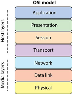
• Figure 9.9 The OSI Reference Model
Packets
Networks are built to share information and resources, but like other forms of communication, networks and the protocols they use have limits and rules that must be followed for effective communication. For example, large chunks of data must typically be broken up into smaller, more manageable chunks before they are transmitted from one computer to another. Breaking the data up has advantages—you can more effectively share bandwidth with other systems and you don’t have to retransmit the entire dataset if there is a problem in transmission. When data is broken up into smaller pieces for transmission, each of the smaller pieces is typically called a packet. Each protocol has its own definition of a packet—dictating how much data can be carried, what information is stored where, how the packet should be interpreted by another system, and so on.
![]()
The concept of breaking a message into pieces before sending it is as old as networking. The terms used to describe these pieces can vary from protocol to protocol. Frame Relay and Ethernet both use the term frame. ATM calls them cells. Many protocols use the generic term packet. In the OSI model, the term datagram is used. At the end of the day, regardless of what it is called, these pieces are protocol-defined, formatted structures used to carry information.
A standard packet structure is a crucial element in a protocol definition. Without a standard packet structure, systems would not be able to interpret the information coming to them from other systems. Packet-based communication systems have other unique characteristics, such as size, that need to be addressed. This is done via a defined maximum and by fragmenting packets that are too big, as shown in the next sections.
Maximum Transmission Unit
When packets are transmitted across a network, there are many intervening protocols and pieces of equipment, each with its own set of limitations. The maximum transmission unit (MTU) is the largest packet that can be carried across a network channel. One of the factors used to determine how many packets a message must be broken into is the MTU. The value of the MTU is used by TCP to prevent packet fragmentation at intervening devices. Packet fragmentation is the splitting of a packet while in transit into two packets so that they fit past an MTU bottleneck.
Packet Fragmentation
Built into the Internet Protocol is a mechanism for the handling of packets that are larger than allowed across a hop. Under ICMP v4, a router has two options when it encounters a packet that is too large for the next hop: break the packet into two fragments, sending each separately, or drop the packet and send an ICMP message back to the originator, indicating that the packet is too big. When a fragmented packet arrives at the receiving host, it must be reunited with the other packet fragments and reassembled. One of the problems with fragmentation is that it can cause excessive levels of packet retransmission because TCP must retransmit an entire packet for the loss of a single fragment. In IPv6, to avoid fragmentation, hosts are required to determine the minimal-path MTU before the transmission of packets to avoid fragmentation en route. Any fragmentation requirements in IPv6 are resolved at the origin, and if fragmentation is required, it occurs before sending.

Tech Tip
IPv6 and Fragmentation
IPv6 systems calculate the MTU and then adhere to that from host to host. This prevents fragmentation en route. Instead, all fragmentation is done by the originating host to fit under the MTU limit.
IP fragmentation can be exploited in a variety of ways to bypass security measures. Packets can be purposefully constructed to split exploit code into multiple fragments to avoid detection by an intrusion detection system (IDS). Because the reassembly of fragments is dependent on data in the fragments, it is possible to manipulate the fragments to result in datagrams that exceed the 64KB limit, resulting in denial of service.
Internet Protocol
The Internet Protocol (IP) is not a single protocol but a suite of protocols. The relationship between some of the IP suite and the OSI model is shown in Figure 9.10. As you can see, there are differences between the two versions of the protocol in use (that is, v4 and v6). The protocol elements and their security implications are covered in the next sections of this chapter. One of these differences is the replacement of the Internet Group Management Protocol (IGMP) with the Internet Control Message Protocol (ICMP) and Multicast Listener Discovery (MLD) in IPv6.

• Figure 9.10 Internet Protocol suite components
IP Packets
To better understand packet structure, let’s examine the packet structure defined by the IP protocol. An IP packet, often called a datagram, has two main sections: the header and the data section (sometimes called the payload). The header section contains all of the information needed to describe the packet (see Figure 9.11).
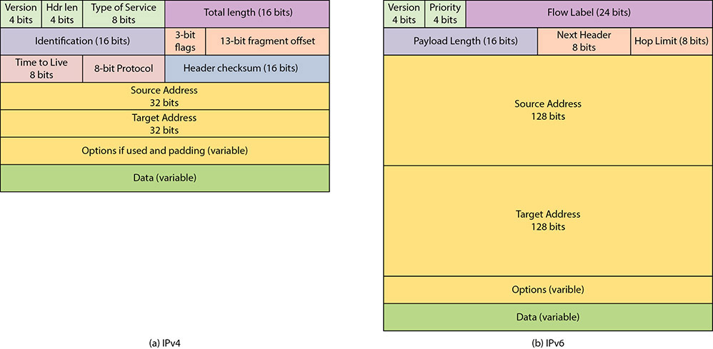
• Figure 9.11 Logical layout of an IP packet: (a) IPv4, (b) IPv6
In IPv4, there are common fields to describe the following options:
![]() What kind of packet it is (protocol version number).
What kind of packet it is (protocol version number).
![]() How large the header of the packet is (packet header length).
How large the header of the packet is (packet header length).
![]() How to process this packet (type of service telling the network whether or not to use options such as minimize delay, maximize throughput, maximize reliability, and minimize cost).
How to process this packet (type of service telling the network whether or not to use options such as minimize delay, maximize throughput, maximize reliability, and minimize cost).
![]() How large the entire packet is (the overall length of packet). Because this is a 16-bit field, the maximum size of an IP packet is 65,535 bytes, but in practice most packets are around 1500 bytes.
How large the entire packet is (the overall length of packet). Because this is a 16-bit field, the maximum size of an IP packet is 65,535 bytes, but in practice most packets are around 1500 bytes.
![]() A unique identifier so that this packet can be distinguished from other packets.
A unique identifier so that this packet can be distinguished from other packets.
![]() Whether or not this packet is part of a longer data stream and should be handled relative to other packets.
Whether or not this packet is part of a longer data stream and should be handled relative to other packets.
![]() Flags that indicate whether or not special handling of this packet is necessary.
Flags that indicate whether or not special handling of this packet is necessary.
![]() A description of where this packet fits into the data stream as compared to other packets (the fragment offset).
A description of where this packet fits into the data stream as compared to other packets (the fragment offset).
![]() A “time to live” field that indicates the packet should be discarded if the value is zero.
A “time to live” field that indicates the packet should be discarded if the value is zero.
![]() A protocol field that describes the encapsulated protocol.
A protocol field that describes the encapsulated protocol.
![]() A checksum of the packet header (to minimize the potential for data corruption during transmission).
A checksum of the packet header (to minimize the potential for data corruption during transmission).
![]() Where the packet is from (source IP address, such as 10.10.10.5).
Where the packet is from (source IP address, such as 10.10.10.5).
![]() Where the packet is going (destination IP address, such as 10.10.10.10).
Where the packet is going (destination IP address, such as 10.10.10.10).
![]() Option flags that govern security and handling restrictions, whether or not to record the route this packet has taken, whether or not to record timestamps, and so on.
Option flags that govern security and handling restrictions, whether or not to record the route this packet has taken, whether or not to record timestamps, and so on.
![]() The data this packet carries.
The data this packet carries.
In IPv6, the source and destination addresses take up much greater room, and for equipment and packet-handling reasons, most of the informational options have been moved to the optional area after the addresses. This series of optional extension headers allows the efficient use of the header in processing the routing information during packet-routing operations.
Tech Tip
The Importance of Understanding TCP/IP Protocols
A security professional must understand how the various TCP/IP protocols operate. For example, if you’re looking at a packet capture of a suspected port scan, you need to know how “normal” TCP and UDP traffic works so you will be able to spot “abnormal” traffic. This chapter provides a very basic overview of the most popular protocols: TCP, UDP, and ICMP.
One of the most common options is the IPSec extension, which is used to establish IPSec connections. IPSec uses encryption to provide a variety of protections to packets. IPSec is fully covered in Chapter 6.
As you can see, this standard packet definition allows systems to communicate. Without this type of “common language,” the global connectivity we enjoy today would be impossible—the IP protocol is the primary means for transmitting information across the Internet.
TCP vs. UDP
Protocols are typically developed to enable a certain type of communication or solve a specific problem. Over the years, this approach has led to the development of many different protocols, each critical to the function or process it supports. However, there are two protocols that have grown so much in popularity and use that, without them, the Internet as we know it would cease to exist. These two protocols, the Transmission Control Protocol (TCP) and User Datagram Protocol (UDP), are ones that run on top of the IP network protocol. As separate protocols, each has its own packet definitions, capabilities, and advantages, but the most important difference between TCP and UDP is the concept of “guaranteed” reliability and delivery.
![]()
TCP is a “connection-oriented” protocol and offers reliability and guaranteed delivery of packets. UDP is a “connectionless” protocol with no guarantees of delivery.
UDP is known as a “connectionless” protocol because it has very few error-recovery services and no guarantee of packet delivery. With UDP, packets are created and sent on their way. The sender has no idea whether the packets were successfully received or whether they were received in order. In that respect, UDP packets are much like postcards—you address them and drop them in the mailbox, not really knowing if, when, or how the postcards reach your intended audience. Even though packet loss and corruption are relatively rare on modern networks, UDP is considered to be an unreliable protocol and is often only used for network services that are not greatly affected by the occasional lost or dropped packet. Time-synchronization requests, name lookups, and streaming audio are good examples of network services based on UDP. UDP also happens to be a fairly “efficient” protocol in terms of content delivery versus overhead. With UDP, more time and space are dedicated to content (data) delivery than with other protocols such as TCP. This makes UDP a good candidate for streaming protocols, as more of the available bandwidth and resources are used for data delivery than with other protocols.
TCP is a “connection-oriented” protocol and was specifically designed to provide a reliable connection between two hosts exchanging data. TCP was also designed to ensure that packets are processed in the same order in which they were sent. As part of TCP, each packet has a sequence number to show where that packet fits into the overall conversation. With the sequence numbers, packets can arrive in any order and at different times, and the receiving system will still know the correct order for processing them. The sequence numbers also let the receiving system know if packets are missing—receiving packets 1, 2, 4, and 7 tells us that packets 3, 5, and 6 are missing and needed as part of this conversation. The receiving system can then request retransmission of packets from the sender to fill in any gaps.
![]()
Think of the three-way handshake as being similar to a phone call. You place a call to your friend—that’s the SYN. Your friend answers the phone and says “hello”—that’s the SYN/ACK. Then you say “Hi, it’s me”—that’s the ACK. Your connection is established, and you can start your conversation.
The “guaranteed and reliable” aspect of TCP makes it very popular for many network applications and services such as HTTP, FTP, and Telnet. As part of the connection, TCP requires that systems follow a specific pattern when establishing communications. This pattern, often called the three-way handshake (shown in Figure 9.12), is a sequence of very specific steps:
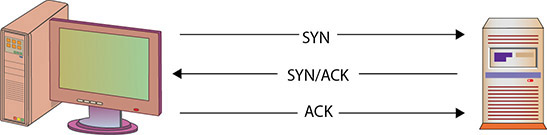
• Figure 9.12 TCP’s three-way handshake
1. The originating host (usually called the client) sends a SYN (synchronize) packet to the destination host (usually called the server). The SYN packet tells the server what port the client wants to connect to and the initial packet sequence number of the client.
2. The server sends a SYN/ACK packet back to the client. This SYN/ACK (synchronize/acknowledge) tells the client “I received your request” and also contains the server’s initial packet sequence number.
3. The client responds to the server with an ACK packet to complete the connection establishment process.
Tech Tip
Encapsulation and Security
A packet is created by aggregation. Working down the OSI stack, the entire datagram becomes the data segment for the next layer, getting a new header. When the TCP header is added, one of the elements is the TCP handshake, which is added to the first packet. The handshake is done by setting bits in the TCP header. This does not prevent data from being transmitted in the first packet, and this has been used by hackers to avoid detection by some security tools. The reason is that many applications wait until the handshake is complete before processing data, but this is not correct because even data on the SYN packet should be processed. The important lesson is to understand how information is embedded in the encapsulation process, both in the header and datagram.
Tearing down a TCP connection can be done in two manners. The first is the transmission of a TCP reset message. This can be done by sending a packet with the TSP RST flag set. The second method is to perform a handshake terminating the connection. The termination handshake is a four-way handshake, as shown in Figure 9.13. If machine A wishes to terminate the connection, it sends a TCP FIN packet to machine B. Machine B acknowledges the request by sending an ACK, including the sequence number +1. Machine B also sends a TCP FIN packet with its own sequence number to A. A then acknowledges the FIN with an acknowledgment of B’s packet +1.
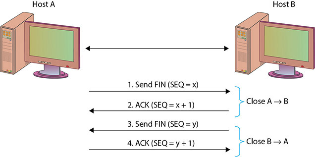
• Figure 9.13 TCP termination process
1. One computer sends a FIN packet to the other computer, including an ACK for the last data received (N).
2. The other computer sends an ACK number of N+1.
3. It also sends a FIN with the sequence number of X.
4. The originating computer sends a packet with an ACK number of N+1
ICMP
While TCP and UDP are arguably the most common protocols, the Internet Control Message Protocol (ICMP) is probably the third most commonly used protocol. During the early development of large networks, it was quickly discovered that there needed to be some mechanism for managing the overall infrastructure—handling connection status, traffic flow, availability, and errors. This mechanism is ICMP. ICMP is a control and information protocol and is used by network devices to determine such things as a remote network’s availability, the length of time to reach a remote network, and the best route for packets to take when traveling to that remote network (using ICMP redirect messages, for example). ICMP can also be used to handle the flow of traffic, telling other network devices to “slow down” transmission speeds if packets are coming in too fast.
Tech Tip
TCP Packet Flags
TCP packets contain flags—dedicated fields that are used to help the TCP protocol control and manage the TCP session. There are eight different flags in a TCP packet, and when a flag is “set,” it has a value of 1. The eight different flags are as follows:
![]() CWR (Congestion Window Reduced) Set by a host to indicate that it received a packet with the ECE flag set and is taking action to help reduce congestion.
CWR (Congestion Window Reduced) Set by a host to indicate that it received a packet with the ECE flag set and is taking action to help reduce congestion.
![]() ECE (ECN-Echo) Indicates that the TCP peer is ECN capable when used during the three-way handshake. During normal traffic, this flag means that a packet with a Congestion Experienced flag in its IP header was received by the host sending this packet.
ECE (ECN-Echo) Indicates that the TCP peer is ECN capable when used during the three-way handshake. During normal traffic, this flag means that a packet with a Congestion Experienced flag in its IP header was received by the host sending this packet.
![]() URG (Urgent) When set, the urgent pointer in the packets should be read as valid and followed for additional data.
URG (Urgent) When set, the urgent pointer in the packets should be read as valid and followed for additional data.
![]() ACK (Acknowledgment) Indicates that the data in the ACK field should be processed.
ACK (Acknowledgment) Indicates that the data in the ACK field should be processed.
![]() PSH (Push) Indicates that data delivery should start immediately rather than waiting for buffers to fill up first.
PSH (Push) Indicates that data delivery should start immediately rather than waiting for buffers to fill up first.
![]() RST (Reset) Resets the current connection. This is a start-over feature often used by IPS/IDS devices to interrupt sessions.
RST (Reset) Resets the current connection. This is a start-over feature often used by IPS/IDS devices to interrupt sessions.
![]() SYN (Synchronize) Used to help synchronize sequence numbers.
SYN (Synchronize) Used to help synchronize sequence numbers.
![]() FIN (Finish) Indicates the sender is finished and has no more data to send.
FIN (Finish) Indicates the sender is finished and has no more data to send.
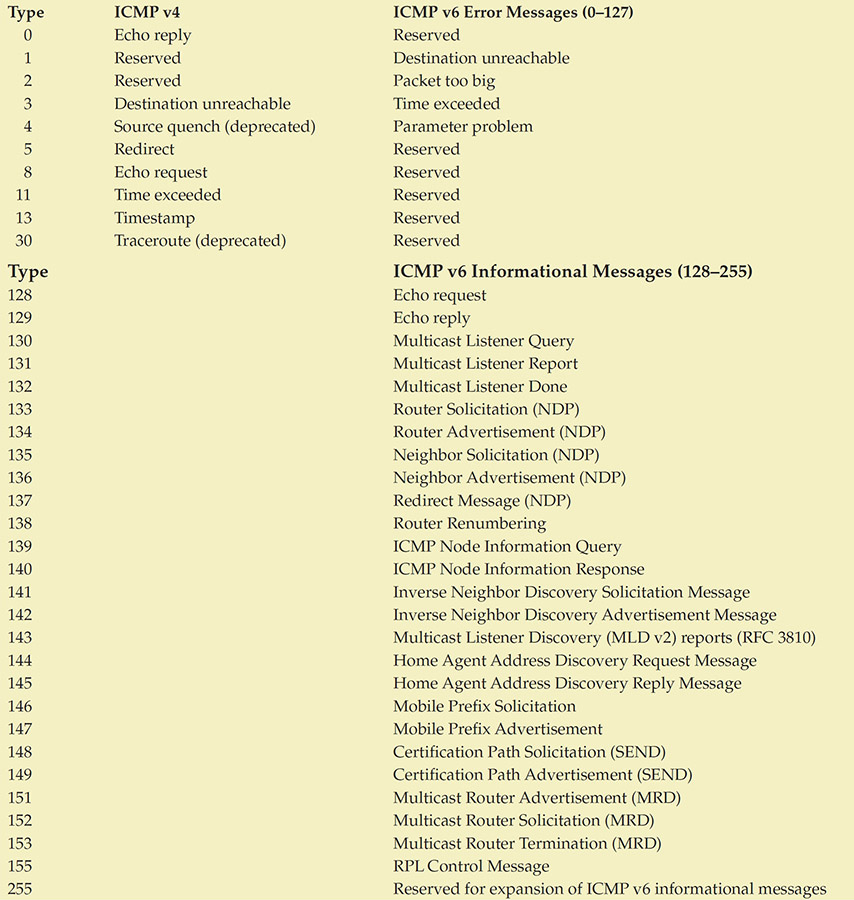
ICMP, like UDP, is a connectionless protocol. ICMP was designed to carry small messages quickly with minimal overhead or impact to bandwidth. ICMP packets are sent using the same header structure as IP packets, with the protocol field set to 1 to indicate that it is an ICMP packet. ICMP packets also have their own header, which follows the IP header and contains type, code, checksum, sequence number, identifier, and data fields. The “type” field indicates what type of ICMP message it is, and the “code” field tells us what the message really means. For example, an ICMP packet with a type of 3 and a code of 2 would tell us this is a “destination unreachable” message and, more specifically, a “host unreachable” message—usually indicating that we are unable to communicate with the intended destination. Because ICMP messages in IPv6 can use IPSec, ICMP v6 messages can have significant protections from alteration.
Unfortunately, ICMP has been greatly abused by attackers over the last few years to execute denial of service (DoS) attacks. Because ICMP packets are very small and connectionless, thousands and thousands of ICMP packets can be generated by a single system in a very short period of time. Attackers have developed methods to trick many systems into generating thousands of ICMP packets with a common destination—the attacker’s target. This creates a literal flood of traffic that the target—and in most cases the network the target sits on—is incapable of dealing with. The ICMP flood drowns out any other legitimate traffic and prevents the target from accomplishing its normal duties, thus denying access to the service the target normally provides. This has led to many organizations blocking all external ICMP traffic at their perimeter.
Tech Tip
ICMP Message Codes
With ICMP packets, the real message of the packet is contained in the “type and code” fields, not the data field. Following are some of the more commonly seen ICMP type codes. Note that ICMP v6 has broken the listing into two types: error messages (0–127) and informational messages (128–255, presented in the latter half of the table).
IPv6 introduced many new protocols, two of which will have significant implications: the Neighbor Discovery Protocol (NDP), which manages the interactions between neighboring IPv6 nodes, and Multicast Listener Discovery (MLD), which manages IPv6 multicast groups.
Tech Tip
ICMPv4 Type 3 Message Codes
Many of the ICMP messages have associated code values that make the message more specific. For example, ICMP v4 messages with a type of 3 can have any of the following codes:

Tech Tip
Should You Block ICMP?
ICMP is a protocol used for troubleshooting, error reporting, and a wide variety of associated functionality. This functionality expands in ICMP v6 into multicasting. ICMP got a bad name primarily because of issues associated with the ping and traceroute commands, but these represent a tiny minority of the protocol functionality. There are numerous, important uses associated with ICMP, and blocking it in its entirety is a bad practice. Blocking specific commands and specific sources makes sense; blanket blocking is a poor practice that will lead to network inefficiencies. Blocking ICMP v6 in its entirety will block a lot of IPv6 functionality because ICMP is now an integral part of the protocol suite.
IPv4 vs. IPv6
The most common version of IP in use is IPv4, but the release of IPv6, spurred by the depletion of the IPv4 address space, has begun a typical logarithmic adoption curve. IPv6 has many similarities to the previous version, but it also has significant new enhancements, many of which have significant security implications.
Expanded Address Space
The expansion of the address space from 32 bits to 128 bits is a significant change. Whereas IPv4 did not have enough addresses for each person on the planet, IPv6 has over 1500 addresses per square meter of Earth’s entire surface. This has one immediate implication: whereas you could use a scanner to search all addresses for responses in IPv4, doing the same in IPv6 will take significantly longer. A one-millisecond scan in IPv4 equates to a 2.5-billion-year scan in IPv6. In theory, the 128 bits of IPv6 address space will allow for 3.4 × 1038 possible nodes. The IPv6 addressing protocol has been designed to allow for a hierarchal division of the address space into several layers of subnets, to assist in the maintaining of both efficient and logical address allocations. One example is the embedding of the IPv4 address space in the IPv6 space. This also has an intentional effect of simplifying the backbone routing infrastructures by reducing the routing table size.
Tech Tip
IPv6 Address Notation
IPv6 addresses are 128 bits long, and a new shorthand has been developed to allow for simple notation of these addresses. The addresses are specified as eight groups of four hexadecimal characters separated by colons. Leading zeroes in any group may be suppressed, and consecutive groups of zeroes may be represented by two colons (::) once in an address. Thus, the IPv6 address of 2001:0ced:7738:0000:0000:0000:00df:1234 can be shortened to 2001:ced:7738::df:1234.
Your local loopback address (which was 127.0.0.1) is now 0:0:0:0:0:0:0:1, or simply ::1. The address 0:0:0:0:0:0:0:0 (or simply ::) is unspecified and is used as a placeholder in messages that need the fields filled but that have no meaning.
There is more than just an expanded address space in size. Each interface has three addresses: link-local, unique-local, and global. Link-local addresses are used for a variety of communications, including mandatory addresses for communication between two IPv6 devices (like ARP but at layer 3). Link-local addresses begin with FE80::. Unique-local addresses are not routable on the Internet and are used for local communications. They are identified by FC00:: at the beginning of the address. Global addresses are good globally and are structured hierarchically.
IPv6 no longer uses the concept of a broadcast message. There are three types of messages:
Unicast Address of a single interface. One-to-one delivery to single interface.
Multicast Address of a set of interfaces. One-to-many delivery to all interfaces in the set.
Anycast Address of a set of interfaces. One-to-one-of-many delivery to a single interface in the set that is closest.
As is becoming readily apparent, IPv6 is substantially more complicated than IPv4, and is much more capable. Further details would require an entire book, and if you will be doing a lot of network-intensive security work, you will need more knowledge in the intricacies of IPv6.
Tech Tip
IPv6 Top Security Concerns
There are numerous IPv6 security concerns—some technical, some operational. Here are some of the top security concerns:
![]() Lack of IPv6 security training/education.
Lack of IPv6 security training/education.
![]() Security device bypass via IPv6.
Security device bypass via IPv6.
![]() Poor IPv6 security policies.
Poor IPv6 security policies.
![]() Address notation makes grepping through logs difficult, if not impossible.
Address notation makes grepping through logs difficult, if not impossible.
![]() IPv6 complexity increases operational challenges for correct deployment.
IPv6 complexity increases operational challenges for correct deployment.
Neighbor Discovery
IPv6 introduces the Neighbor Discovery Protocol (NDP), which is useful for auto-configuration of networks. NDP can enable a variety of interception and interruption threat modes. A malevolent router can attach itself to a network and then reroute or interrupt traffic flows. In IPv6, there is no longer an Address Resolution Protocol (ARP) function. The function of ARP is replaced in IPv6 by Neighbor Solicitation (NS) messages.
Figure 9.14 shows the results of an IPv4 arp command on a Windows system, which results in the dumping of the local cache to the screen. Figure 9.15 shows the equivalent request on a Windows IPv6 system, where the command results in an ICMPv6 Neighbor Solicitation request (code = 135), which gets an ICMPv6 Neighbor Advertisement (code = 136) response. DHCPv6 has undergone a similar rework so that it can interface with NDP and allow auto-configuration of devices.
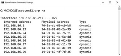
• Figure 9.14 IPv4 arp command in Windows

• Figure 9.15 IPv6 NS request in Windows
Benefits of IPv6
Change is always a difficult task, and when the change will touch virtually everything in your system, this makes it even more difficult. Changing from IPv4 to IPv6 is not a simple task because it will have an effect on every networked resource. The good news is that this is not a sudden or surprise process; vendors have been making IPv6-capable products for almost a decade. By this point, virtually all the network equipment you rely on will be dual-stack capable, meaning that it can operate in both IPv4 and IPv6 networks. This provides a method for an orderly transfer from IPv4 to IPv6.
IPv6 has many useful benefits and ultimately will be more secure because it has many security features built into the base protocol series. IPv6 has a simplified packet header and new addressing scheme. This can lead to more efficient routing through smaller routing tables and faster packet processing. IPv6 was designed to incorporate multicasting flows natively, which allows bandwidth-intensive multimedia streams to be sent simultaneously to multiple destinations. IPv6 has a host of new services, from auto-configuration to mobile device addressing, as well as service enhancements to improve the robustness of quality of service (QoS) and Voice over IP (VoIP) functions.
The security model of IPv6 is baked into the protocol and is significantly enhanced from the nonexistent one in IPv4. IPv6 is designed to be secure from sender to receiver, with IPSec available natively across the protocol. This will significantly improve communication-level security, but it has also drawn a lot of attention. The use of IPSec will change the way security functions are performed across the enterprise. Old IPv4 methods, such as NAT and packet inspection methods of IDS, will need to be adjusted to the new model. Security appliances will have to adapt to the new protocol and its enhanced nature.
Packet Delivery
Protocols are designed to help information get from one place to another, but in order to deliver a packet, we have to know where it is going. Packet delivery can be divided into two sections: local and remote. Ethernet is common for local delivery, whereas IP works for remote delivery. Local packet delivery applies to packets being sent out on a local network, whereas remote packet delivery applies to packets being delivered to a remote system, such as across the Internet. Ultimately, packets may follow a “local delivery–remote delivery–local delivery” pattern before reaching their intended destination. The biggest difference in local versus remote delivery is how packets are addressed. Network systems have addresses, not unlike office numbers or street addresses, and before a packet can be successfully delivered, the sender needs to know the address of the destination system.
Tech Tip
MAC Addresses
Every network device should have a unique MAC address. Manufacturers of network cards and network chipsets have blocks of MAC addresses assigned to them, so you can often tell what type of equipment is sending packets by looking at the first three pairs of hexadecimal digits in a MAC address. For example, “00-00-0C” would indicate the network device was built by Cisco Systems.
Ethernet
Ethernet is the most widely implemented Layer 2 protocol. Ethernet is standardized under IEEE 802.3. Ethernet works by forwarding packets on a hop-to-hop basis using MAC addresses. Layer 2 addressing can have numerous security implications. Layer 2 addresses can be poisoned, spanning tree algorithms can be attacked, VLANs can be hopped, and more. Because of its near ubiquity, Ethernet is a common attack vector. It has many elements that make it useful from a networking point of view, such as its broadcast nature and its ability to run over a wide range of media. But these can also act against security concerns. Wireless connections are frequently considered to be weak from a security point of view, but so should Ethernet—unless you own the network, you should consider the network to be at risk.
Local Packet Delivery
Packets delivered on a network, such as an office LAN, are usually sent using the destination system’s hardware address, or Media Access Control (MAC) address. Each network card or network device is supposed to have a unique hardware address so that it can be specifically addressed for network traffic. MAC addresses are assigned to a device or network card by the manufacturer, and each manufacturer is assigned a specific block of MAC addresses to prevent two devices from sharing the same MAC address. MAC addresses are usually expressed as six pairs of hexadecimal digits, such as 00:07:e9:7c:c8:aa. In order for a system to send data to another system on the network, it must first find out the destination system’s MAC address.
![]()
Try This!
Finding MAC Addresses on Windows Systems
Open a command prompt on a Windows system. Type the command ipconfig /all and find your system’s MAC address. (Hint: It should be listed under “Physical Address” on your network adapters.) Now type the command arp –a and press ENTER. What information does this display? Can you find the MAC address of your default gateway?
Maintaining a list of every local system’s MAC address is both costly and time consuming, and although a system may store MAC addresses temporarily for convenience, in many cases the sender must find the destination MAC address before sending any packets. To find another system’s MAC address, the Address Resolution Protocol (ARP) is used. Essentially, this is the computer’s way of finding out “who owns the blue convertible with license number 123JAK.” In most cases, systems know the IP address they wish to send to, but not the MAC address. Using an ARP request, the sending system will send out a query: Who is 10.1.1.140? This broadcast query is examined by every system on the local network, but only the system whose IP address is 10.1.1.140 will respond. That system will send back a response that says, “I’m 10.1.1.140 and my MAC address is 00:07:e9:7c:c8:aa.” The sending system will then format the packet for delivery and drop it on the network media, stamped with the MAC address of the destination workstation.
![]()
MAC addresses can be “spoofed,” or faked. Some operating systems allow users with administrator-level privileges to explicitly set the MAC address for their network card(s). For example, in Linux operating systems you can use the ifconfig command to change a network adapter’s MAC address. The command ifconfig eth0 hw ether 00:07:e9:7c:c8:aa will set the MAC address of adapter eth0 to 00:07:e9:7c:c8:aa. Also, a number of software utilities allow you to do this through a GUI, such as the GNU MAC Changer. GUI utilities to change MAC addresses on Windows systems are also available.
![]()
Cross Check
Mandatory Access Control vs. Media Access Control
In Chapter 11 you will learn about a different acronym: MAC, for mandatory access control. What is the difference between mandatory access control and Media Access Control? What is each used for? When using acronyms, it can be critical to ensure all parties are aware of the context of their usage.
ARP Attacks
Address Resolution Protocol (ARP) operates in a simplistic and efficient manner—a broadcast request followed by a unicast reply. This method leaves ARP open to attack, which in turn can result in the loss of integrity, confidentiality, and availability. Because ARP serves to establish communication channels, failures at this level can lead to significant system compromises. There is a wide range of ARP-specific attacks, but one can classify them into types based on effect.
Tech Tip
Rogue Device Detection
There is always a risk of a rogue (unauthorized) device being inserted into the network. Maintaining a list of all authorized MAC addresses can help detect these devices. Although MACs can be copied and spoofed, this would also set up a conflict if the original device was present. Monitoring for these conditions can detect the insertion of a rogue device.
ARP can be a vector employed to achieve a man-in-the-middle (on-path) attack. There are many specific ways to create false entries in a machine’s ARP cache, but the effect is the same: communications will be routed to an attacker. This type of attack is called ARP poisoning. The attacker can use this method to inject himself into the middle of a communication, hijack a session, sniff traffic to obtain passwords or other sensitive items, or block the flow of data, creating a denial of service.
Although ARP is not secure, all is not lost with many ARP-based attacks. Higher-level packet protections such as IPSec can be employed so that the packets are unreadable by interlopers. This is one of the security gains associated with IPv6, because when security is employed at the IPSec level, packets are protected below the IP level, making Layer 2 attacks less successful.
Remote Packet Delivery
While packet delivery on a LAN is usually accomplished with MAC addresses, packet delivery to a distant system is usually accomplished using Internet Protocol (IP) addresses. IP addresses are 32-bit numbers that usually are expressed as a group of four numbers (such as 10.1.1.132). In order to send a packet to a specific system on the other side of the world, you have to know the remote system’s IP address. Storing large numbers of IP addresses on every PC is far too costly, and most humans are not good at remembering collections of numbers. However, humans are good at remembering names, so the Domain Name System (DNS) protocol was created.
DNS
DNS translates names into IP addresses. When you enter the name of your favorite website into the location bar of your web browser and press ENTER, the computer has to figure out what IP address belongs to that name. Your computer takes the entered name and sends a query to a local DNS server. Essentially, your computer asks the DNS server, “What IP address goes with www.myfavoritesite.com?” The DNS server, whose main purpose in life is to handle DNS queries, looks in its local records to see if it knows the answer. If it doesn’t, the DNS server queries another, higher-level domain server. That server checks its records and queries the server above it, and so on, until a match is found. That name-to-IP-address matching is passed back down to your computer so it can create the web request, stamp it with the right destination IP address, and send it.
![]()
The Domain Name System is critical to the operation of the Internet—if your computer can’t translate www.espn.com into 68.71.212.159, then your web browser won’t be able to access the latest scores. (Because DNS is a dynamic system, the IP address may change for www.espn.com; you can check with the tracert command.)
Before sending the packet, your system will first determine if the destination IP address is on a local or remote network. In most cases, it will be on a remote network and your system will not know how to reach that remote network. Again, it would not be practical for your system to know how to directly reach every other system on the Internet, so your system will forward the packet to a network gateway. Network gateways, usually called routers, are devices that are used to interconnect networks and move packets from one network to another. That process of moving packets from one network to another is called routing and is critical to the flow of information across the Internet. To accomplish this task, routers use forwarding tables to determine where a packet should go. When a packet reaches a router, the router looks at the destination address to determine where to send the packet. If the router’s forwarding tables indicate where the packet should go, the router sends the packet out along the appropriate route. If the router does not know where the destination network is, it forwards the packet to its defined gateway, which repeats the same process. Eventually, after traversing various networks and being passed through various routers, your packet arrives at the router serving the network with the website you are trying to reach. This router determines the appropriate MAC address of the destination system and forwards the packet accordingly.
A request to a DNS server can return a significant amount of information in the form of records. There are several record types, as shown in Table 9.1.
Table 9.1 A Sample of DNS Record Types

There are many more record types used for specific purposes. The total number of types is over 40.
DNSSEC
Because of the critical function DNS performs and the security implications of DNS, a cryptographically signed version of DNS was created. DNSSEC (short for DNS Security Extensions) is an extension of the original DNS specification, making it trustworthy. DNS is one of the pillars of authority associated with the Internet—it provides the addresses used by machines for communications. Lack of trust in DNS and the inability to authenticate DNS messages drove the need for and creation of DNSSEC. The DNSSEC specification was formally published in 2005, but system-wide adoption has been slow. In 2008, Dan Kaminsky introduced a method of DNS cache poisoning, demonstrating the need for DNSSEC adoption. Although Kaminsky worked with virtually all major vendors and was behind one of the most coordinated patch rollouts ever, the need for DNSSEC still remains, and enterprises are slow to adopt the new methods. One of the reasons for slow adoption is complexity. Having DNS requests and replies digitally signed requires significantly more work, and the increase in complexity goes against the stability desires of network engineers.
DNSSEC was designed to protect DNS client resolvers from accepting forged DNS data, such as sent in a DNS cache poisoning attack. DNS answers in DNSSEC are digitally signed, providing a means of verifying integrity. DNSSEC adds new records to the DNS protocol, as well as new header flags. The records are Resource Record Signature (RRSIG), DNS Public Key (DNSKEY), Delegation Signer (DS), and Next Secure (NSEC/NSEC2). The new flags are Checking Disabled (CD) and Authenticated Data (AD). When a DNS request is received, DNS provides a signed response, enabling the receiver of the response to have trust that the answer came from a reliable source.
Tech Tip
How DNS Works
DNS is a hierarchical distributed database structure of names and addresses. This system is delegated from root servers to other DNS servers that each manage local requests for information. The top level of authorities, referred to as authoritative sources, maintain the correct authoritative record. As records change, they are pushed out among the DNS servers, so records can be maintained in as near a current fashion as possible. Transfers of DNS records between DNS servers are called DNS zone transfers. Because these can result in massive poisoning attacks, zone transfers need to be tightly controlled between trusted parties.
To avoid request congestion, DNS responses are handled by a myriad of lower name servers, referred to as resolvers. Resolvers have a counter that refreshes their record after a time limit has been reached. Under normal operation, the DNS function is a two-step process:
1. The client requests a DNS record.
2. The resolver replies with a DNS reply.
If the resolver is out of date, the steps expand:
1. The client requests a DNS record.
2. The recursive resolver queries the authoritative server.
3. The authoritative server replies to the recursive resolver.
4. The recursive resolver replies with a DNS response to client.
DNS was designed in the 1980s when the threat model was substantially different than today. The Internet today, and its use for all kinds of critical communications, needs a trustworthy addressing mechanism. DNSSEC is that mechanism, and as it rolls out, it will significantly increase the level of trust associated with addresses. Although certificate-based digital signatures are not perfect, the level of effort to compromise this type of protection mechanism changes the nature of the attack game, making it out of reach to all but the most resourced players. The coupled nature of the trust chains in DNS also serves to alert to any intervening attacks, making attacks much harder to hide.
DNS over HTTPS (DoH)
Domain Name System (DNS) over Hypertext Transfer Protocol using Transport Layer Security (HTTPS) is referred to as DNS over HTTPS (DoH). DoH is useful in preventing eavesdropping and manipulation of DNS traffic, as it encrypts DNS requests to provide privacy, integrity, and source authentication for DNS transactions with a client’s DNS resolver. While DoH is useful to protect DNS information transfers from attackers, it can cause issues with enterprise monitoring of DNS traffic. These monitoring issues can be overcome, but the main risk is in connecting to external DNS providers using DoH—connections that would be difficult to monitor and control at the edge of the network.
Tech Tip
DNS in the Enterprise Environment
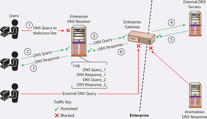
1. The user wants to visit a website they do not know is malicious and types the domain name into the web browser. The enterprise DNS resolver blocks the request.
2. The request for the domain name is sent to the enterprise DNS resolver with a plaintext packet on port 53. Queries that violate DNS monitoring policies should generate alerts and/or be blocked.
3. If the IP address for the domain is not in the enterprise DNS resolver’s cache of domains and the domain is not filtered, a DNS query will be sent through the enterprise gateway.
4. The enterprise gateway forwards the plaintext DNS request to an external DNS server. It also blocks DNS requests not from the enterprise DNS resolver.
5. The response to the query with the IP address of the domain, the address of another DNS server with more information, or an error is returned in plaintext back through the enterprise gateway.
6. The enterprise gateway forwards the response back to the enterprise DNS resolver. Steps 3–6 repeat until either the IP address for the requested domain name is found or there is an error.
7. The DNS resolver returns the response back to the user’s web browser, which then requests the web page from the IP address in the response.
Source: “Adopting Encrypted DNS in Enterprise Environments.” National Security Agency. https://media.defense.gov/2021/Jan/14/2002564889/-1/-1/0/CSI_ADOPTING_ENCRYPTED_DNS_U_OO_102904_21.PDF
Dynamic Host Configuration Protocol
When an administrator sets up a network, they usually assign IP addresses to systems in one of two ways: statically or through DHCP. A static IP address assignment is fairly simple; the administrator decides what IP address to assign to a server or PC, and that IP address stays assigned to that system until the administrator decides to change it. The other popular method is through the Dynamic Host Configuration Protocol (DHCP). Under DHCP, when a system boots up or is connected to the network, it sends out a query looking for a DHCP server. If a DHCP server is available on the network, it answers the new system and temporarily assigns to the new system an IP address from a pool of dedicated, available addresses. DHCP is an “as available” protocol—if the server has already allocated all the available IP addresses in the DHCP pool, the new system will not receive an IP address and will not be able to connect to the network. Another key feature of DHCP is the ability to limit how long a system may keep its DHCP-assigned IP address. DHCP addresses have a limited lifespan, and once that time period expires, the system using that IP address must either renew use of that address or request another address from the DHCP server. The requesting system either may end up with the same IP address or may be assigned a completely new address, depending on how the DHCP server is configured and on the current demand for available addresses. DHCP is very popular in large user environments where the cost of assigning and tracking IP addresses among hundreds or thousands of user systems is extremely high.
IP Addresses and Subnetting
As you’ll recall from earlier in the chapter, IPv4 addresses are 32-bit numbers. Those 32 bits are represented as four groups of 8 bits each (called octets). You will usually see IP addresses expressed as four sets of decimal numbers in dotted-decimal notation (10.120.102.15, for example). Of those 32 bits in an IP address, some are used for the network portion of the address (the network ID), and some are used for the host portion of the address (the host ID). Subnetting is the process that is used to divide those 32 bits in an IP address and tell you how many of the 32 bits are being used for the network ID and how many are being used for the host ID. As you can guess, where and how you divide the 32 bits determines how many networks and how many host addresses you may have. To interpret the 32-bit space correctly, we must use a subnet mask, which tells us exactly how much of the space is the network portion and how much is the host portion. Let’s look at an example using the IP address 10.10.10.101 with a subnet mask of 255.255.255.0.
First, we must convert the address and subnet mask to their binary representations:
Subnet mask: 11111111.11111111.11111111.00000000
IP address: 00001010.00001010.00001010.01100101
Then, we perform a bitwise AND operation to get the network address. The bitwise AND operation examines each set of matching bits from the binary representation of the subnet mask and the binary representation of the IP address. For each set where both the mask and address bits are 1, the result of the AND operation is a 1. Otherwise, if either bit is a 0, the result is a 0. So, for our example we get
Subnet mask: 11111111.11111111.11111111.00000000
IP address: 00001010.00001010.00001010.01100101
Network address: 00001010.00001010.00001010.00000000
which in decimal is 10.10.10.0, the network ID of our IP network address (translate the binary representation to decimal). Note how the fourth octet of 00000000 in the mask in effect removes the last octet of the IP address, converting it to all zeroes.
The network ID and subnet mask together tell us that the first three octets of our address are network related (10.10.10.), which means that the last octet of our address is the host portion (101 in this case). In our example, the network portion of the address is 10.10.10 and the host portion is 101. Another shortcut in identifying which of the 32 bits is being used in the network ID is to look at the subnet mask after it has been converted to its binary representation. If there’s a 1 in the subnet mask, the corresponding bit in the binary representation of the IP address is being used as part of the network ID. In the preceding example, the subnet mask of 255.255.255.0 in binary representation is 11111111.11111111.11111111.00000000. We can see that there’s a 1 in the first 24 spots, which means that the first 24 bits of the IP address are being used as the network ID (which is the first three octets of 255.255.255).
Tech Tip
RFC 1918: Private Address Spaces
RFC 1918 is the technical specification for private address space. RFC stands for Request for Comment, and there are RFCs for just about everything to do with the Internet—protocols, routing, how to handle e-mail, and so on. You can find RFCs at www.ietf.org/rfc.html.
Network address spaces are usually divided into one of three classes:
![]() Class A Supports 16,777,214 hosts on each network, with a default subnet mask of 255.0.0.0. Subnets: 0.0.0.0 to 126.255.255.255 (127.0.0.0 to 127.255.255.255 is reserved for loopback).
Class A Supports 16,777,214 hosts on each network, with a default subnet mask of 255.0.0.0. Subnets: 0.0.0.0 to 126.255.255.255 (127.0.0.0 to 127.255.255.255 is reserved for loopback).
![]() Class B Supports 65,534 hosts on each network, with a default subnet mask of 255.255.0.0. Subnets: 128.0.0.0 to 191.255.255.255.
Class B Supports 65,534 hosts on each network, with a default subnet mask of 255.255.0.0. Subnets: 128.0.0.0 to 191.255.255.255.
![]() Class C Supports 253 hosts on each network, with a default subnet mask of 255.255.255.0 (see Figure 9.16). Subnets: 192.0.0.0 to 223.255.255.255.
Class C Supports 253 hosts on each network, with a default subnet mask of 255.255.255.0 (see Figure 9.16). Subnets: 192.0.0.0 to 223.255.255.255.
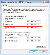
• Figure 9.16 A subnet mask of 255.255.255.0 indicates this is a Class C address space.
Everything above 224.0.0.0 is reserved for either multicasting or future use.
In addition, certain subnets are reserved for private use and are not routed across public networks such as the Internet:
![]() 10.0.0.0 to 10.255.255.255
10.0.0.0 to 10.255.255.255
![]() 172.16.0.0 to 172.31.255.255
172.16.0.0 to 172.31.255.255
![]() 192.168.0.0 to 192.168.255.255
192.168.0.0 to 192.168.255.255
![]() 169.254.0.0 to 169.254.255.255 (Automatic Private IP Addressing)
169.254.0.0 to 169.254.255.255 (Automatic Private IP Addressing)
Finally, when determining the valid hosts that can be placed on a particular subnet, you have to keep in mind that the “all 0’s” address of the host portion is reserved for the network address, and the “all 1’s” address of the host portion is reserved for the broadcast address of that particular subnet. Again from our earlier example:
Subnet network address:
10.10.10.0
00001010.00001010.00001010.00000000
Broadcast address:
10.10.10.255
00001010.00001010.00001010.11111111
In their forwarding tables, routers maintain lists of networks and the accompanying subnet mask. With these two pieces, the router can examine the destination address of each packet and then forward the packet on to the appropriate destination.
As mentioned earlier, subnetting allows us to divide networks into smaller logical units, and we use subnet masks to do this. But how does this work? Remember that the subnet mask tells us how many bits are being used to describe the network ID—adjusting the subnet mask (and the number of bits used to describe the network ID) allows us to divide an address space into multiple, smaller logical networks. Let’s say you have a single address space of 192.168.45.0 that you need to divide into multiple networks. The default subnet mask is 255.255.255.0, which means you’re using 24 bits as the network ID and 8 bits as the host ID. This gives you 254 different host addresses. But what if you need more networks and don’t need as many host addresses? You can simply adjust your subnet mask to borrow some of the host bits and use them as network bits. If you use a subnet mask of 255.255.255.224, you are essentially “borrowing” the first 3 bits from the space you were using to describe host IDs and using them to describe the network ID. This gives you more space to create different networks but means that each network will now have fewer available host IDs. With a 255.255.255.224 subnet mask, you can create six different subnets, but each subnet can only have 30 unique host IDs. If you borrow 6 bits from the host ID portion and use a subnet mask of 255.255.255.252, you can create 62 different networks, but each of them can only have two unique host IDs.
![]()
Try This!
Calculating Subnets and Hosts
Given a network ID of 192.168.10.X and a subnet mask of 255.255.255.224, you should be able to create eight networks with space for 30 hosts on each network. Calculate the network address, the first usable IP address in that subnet, and the last usable IP address in that subnet. (Hint: The first network will be 192.168.10.0. The first usable IP address in that subnet is 192.168.10.1, and the last usable IP address in that subnet is 192.168.10.30.)
Network Address Translation
If you’re thinking that a 32-bit address space that’s chopped up and subnetted isn’t enough to handle all the systems in the world, you’re right. While IPv4 address blocks are assigned to organizations such as companies and universities, there usually aren’t enough Internet-visible IP addresses to assign to every system on the planet a unique, Internet-routable IP address. To compensate for this lack of available IP address space, we use Network Address Translation (NAT). NAT translates private (nonroutable) IP addresses into public (routable) IP addresses.
From our discussions earlier in this chapter, you may remember that certain IP address blocks are reserved for “private use,” and you’d probably agree that not every system in an organization needs a direct, Internet-routable IP address. Actually, for security reasons, it’s much better if most of an organization’s systems are hidden from direct Internet access. Most organizations build their internal networks using the private IP address ranges (such as 10.1.1.X) to prevent outsiders from directly accessing those internal networks. However, in many cases those systems still need to be able to reach the Internet. This is accomplished by using a NAT device (typically a firewall or router) that translates the many internal IP addresses into one of a small number of public IP addresses.
For example, consider a fictitious company, ACME.com. ACME has several thousand internal systems using private IP addresses in the 10.X.X.X range. To allow those IPs to communicate with the outside world, ACME leases an Internet connection and a few public IP addresses, and it deploys a NAT-capable device. ACME administrators configure all their internal hosts to use the NAT device as their default gateway. When internal hosts need to send packets outside the company, they send them to the NAT device. The NAT device removes the internal source IP address out of the outbound packets and replaces it with the NAT device’s public, routable address and then sends the packets on their way. When response packets are received from outside sources, the device performs NAT in reverse, stripping off the external, public IP address in the destination address field and replacing it with the correct internal, private IP address in the destination address field before sending it on into the private ACME.com network. Figure 9.17 illustrates this NAT process.

• Figure 9.17 Logical depiction of NAT
Tech Tip
Different Approaches for Implementing NAT
Although the concept of NAT remains the same, there are actually several different approaches to implementing it:
![]() Static NAT Maps an internal, private address to an external, public address. The same public address is always used for that private address. This technique is often used when hosting something you wish the public to be able to get to, such as a web server behind a firewall.
Static NAT Maps an internal, private address to an external, public address. The same public address is always used for that private address. This technique is often used when hosting something you wish the public to be able to get to, such as a web server behind a firewall.
![]() Dynamic NAT Maps an internal, private IP address to a public IP address selected from a pool of registered (public) IP addresses. This technique is often used when translating addresses for end-user workstations and the NAT device must keep track of internal/external address mappings.
Dynamic NAT Maps an internal, private IP address to a public IP address selected from a pool of registered (public) IP addresses. This technique is often used when translating addresses for end-user workstations and the NAT device must keep track of internal/external address mappings.
![]() Port Address Translation (PAT) Allows many different internal, private addresses to share a single external IP address. Devices performing PAT replace the source IP address with the NAT IP address and replace the source port field with a port from an available connection pool. PAT devices keep a translation table to track which internal hosts are using which ports so that subsequent packets can be stamped with the same port number. When response packets are received, the PAT device reverses the process and forwards the packet to the correct internal host. PAT is a very popular NAT technique and is in use at many organizations.
Port Address Translation (PAT) Allows many different internal, private addresses to share a single external IP address. Devices performing PAT replace the source IP address with the NAT IP address and replace the source port field with a port from an available connection pool. PAT devices keep a translation table to track which internal hosts are using which ports so that subsequent packets can be stamped with the same port number. When response packets are received, the PAT device reverses the process and forwards the packet to the correct internal host. PAT is a very popular NAT technique and is in use at many organizations.
In Figure 9.17, we see an example of NAT being performed. An internal workstation (10.10.10.12) wants to visit the ESPN website at www.espn.com (68.71.212.159). When the packet reaches the NAT device, the device translates the 10.10.10.12 source address to the globally routable 63.69.110.110 address, the IP address of the device’s externally visible interface. When the ESPN website responds, it responds to the device’s address, just as if the NAT device had originally requested the information. The NAT device must then remember which internal workstation requested the information and route the packet to the appropriate destination.
Inter-Networking
The Internet is viewed by many as a single large network, but it is in reality a series of interconnected networks. These systems are called autonomous systems (ASs), and they have their own standard protocol methods of communications. The Border Gateway Protocol (BGP) is used to manage routing and reachability information between adjoining ASs. There are tens of thousands of ASs, from individual campus networks, to ISPs, to major corporations and government agencies. The routing of information between these ASs is done using BGP—specifically, external BGP, or eBGP.
BGP can have a huge effect on global traffic if it is incorrectly configured. On more than one occasion, a communications provider has provided bad information to the BGP system. The effect can be to capture or block Internet traffic. In 2004, a Turkish ISP improperly coded a BGP route, forcing all of the Internet to try and route through the ISP. In a separate instance in 2008, a Pakistani ISP put a BGP route in place to block Pakistani users from being able to access YouTube. The result ended up as a near worldwide block as the route moved from AS to AS.
BGP can be hijacked as well, and because of its widespread implementation, it is difficult to change, as this act would require coordination between virtually every AS for a simultaneous switching of the protocol specifics.
MPLS
Multi-protocol label switching (MPLS) is an underlay technology; specifically, it’s a network that sits beneath the network infrastructure and provides connectivity. Because MPLS operates across switched telecommunication circuits, it has a performance advantage over the packet-switched Internet, with reduced jitter and latency. MPLS is a high-performance telecommunications data-carrying technique used to connect multiple sites and can carry multiple different types of traffic, including VoIP, video conferencing, and virtual/remote desktop operations. MPLS operates by placing labels onto the packets and moving them via switching as opposed to routing. MPLS operates at layer 2 instead of layer 3, providing increased performance between defined nodes. MPLS offers higher, guaranteed performance, but at a higher cost due to the use of private networks as opposed to the public-based Internet.
Software-Defined Networking (SDN)
Software-defined networking (SDN) is a network architecture where the control plane and the data plane are separated. This allows for networking hardware to be under programmatic control, even while processing data. Traditional network architectures have the data plane and the control plane coexisting, and one of the results is the reduced flexibility of changing the network. This comes as a result of the scope of communications with respect to data. Where a data stream doesn’t go has only limited programmability options. With SDN, a complete network programming stack exists, separate from data flows and programmable across the entire network. This provides significant flexibility and programmability in SDN networks, although at the cost of complexity. A key element of SDN is network function virtualization (NFV). NFV is an architecture that virtualizes network services, such as routers, firewalls, and load balancers, as opposed to running them on dedicated, specific hardware. Together, SDN and NFV create a fully functional network under the Infrastructure as Code architectural model.
From a security perspective, SDN adds advantages and disadvantages. In today’s virtualized server world, servers can be spun up and moved with simple commands from orchestration software. This makes server deployment from model (that is, secure) exemplars fast and easy. SDN promises the same for network function deployment, such as firewalls. Network function virtualization (NFV) offers many of the same advantages that server virtualization offers. Preconfigured firewalls can be moved into traffic patterns with the simple command of the orchestration software. On the disadvantage side, the actual SDN software itself can increase the attack surface, and there are currently no good tools to monitor the SDN software for misuse or corruption.
A specific subset of SDN is software-defined wide area networking (SD-WAN). SD-WAN refers to the use of software to implement and manage a wide area network. This includes virtualizing network functions such as routers and firewalls, as well as network centralization. There are firms that have created specific SD-WAN implementations as an alternative to MPLS network technologies. Unlike MPLS, which is an underlay technology, SD-WAN is an overlay technology. SD-WAN technology uses software to create layers of network abstraction that can be used to run multiple discrete virtualized network layers over the physical layer. This makes SD-WAN implementations still subject to the underlying jitter and latency issues associated with the Internet.
Software-Defined Visibility (SDV)
For a network device to operate on data, it must see the data flow. Firewalls can’t manage data they don’t see, so firewalls are physically positioned throughout the network in line with the system’s physical architecture. Just as software-defined networking has changed how networks are managed, software-defined visibility (SDV) is an extension of this Infrastructure as Code idea for the network visibility problem. Rather than the next-generation firewall (NGFW) being positioned strategically in line with data flows physically, it is done via code through the SDN fabric. This allows flexibility in design and the ability to reconfigure networks on the fly, including the security components.
Quality of Service (QoS)
Quality of service (QoS) is the use of specific technologies on a network to guarantee its ability to manage traffic based on a variety of indicators. High-bandwidth, real-time traffic, such as Voice over IP (VoIP), video conferencing, and video-on-demand, has a high sensitivity to network issues such as latency and jitter. QoS technologies are used to manage network conditions such as bandwidth (throughput), latency (delay), jitter (variance in latency), and error rates. They do this by providing differentiated handling and capacity allocation to specific flows based on packet type and source. QoS enables network administrators to assign the priority in which packets are handled as well as the amount of bandwidth afforded to that application or traffic flow.
Traffic Engineering
Traffic engineering is the set of processes and procedures used by network operators to efficiently deal with large amounts of data flowing through their networks. Traffic engineering involves manipulating the network to relieve congestion and balance loads more evenly across paths. While the protocols used in networking may operate independently of outside influence, they do not always work to optimal efficiencies, especially with heavy traffic loads. Traffic engineering deals with creating efficient network routes that reduce issues such as jitter and latency.
Route Security
Routing is the basis of interconnecting networks that comprise the Internet. Packets cross the networks to move information from source to destination. Depending on where the source and destination are with respect to each other, the route a packet takes can be wide ranging, from simple and short to complex and long. The protocols used to connect the various networks range from simple, like the Internet Protocol (IP), to more complex, such as BGP, IS-IS, OSPF, EIGRP, and RIPv2. Maintaining route security is part of the function of each of these protocols, and each serves to fulfill a specific needed functionality in connecting networks. From a Security+ perspective, the details behind each of these protocols is out of scope for this book, but understanding that they work together both to enable network functionality and secure packet transfers is important.
For More Information
Networking CompTIA Network+ Certification All-in-One Exam Guide, Seventh Edition, McGraw Hill, 2018
The Internet Engineering Task Force www.ietf.org
Chapter 9 Review
 Chapter Summary
After reading this chapter and completing the exercises, you should understand the following about networks.
Identify the basic network architectures
![]() The two broad categories of networks are LANs and WANs.
The two broad categories of networks are LANs and WANs.
![]() The physical arrangement of a network is typically called the network’s topology.
The physical arrangement of a network is typically called the network’s topology.
![]() The four main types of network topologies are ring, bus, star, and mixed.
The four main types of network topologies are ring, bus, star, and mixed.
![]() Additional architectures include wireless and ad hoc.
Additional architectures include wireless and ad hoc.
Examine segregation, segmentation, and isolation with respect to network architectures
![]() Understand both physical and logical structures, and their differences.
Understand both physical and logical structures, and their differences.
![]() The use of airgaps, zones, and conduits in control system architectures is a key element of their network security architecture.
The use of airgaps, zones, and conduits in control system architectures is a key element of their network security architecture.
![]() Enclaves act as local segregation entities.
Enclaves act as local segregation entities.
![]() Using zero trust for the authentication model changes the old perimeter security model of networks.
Using zero trust for the authentication model changes the old perimeter security model of networks.
Classify security zones
![]() A DMZ is a buffer zone between networks with different trust levels. Companies often place public resources in a DMZ so that Internet users and internal users may access those resources without exposing the internal company network to the Internet.
A DMZ is a buffer zone between networks with different trust levels. Companies often place public resources in a DMZ so that Internet users and internal users may access those resources without exposing the internal company network to the Internet.
![]() An intranet is a private, internal network that uses common network technologies (HTTP, FTP, and so on) to share information and provide resources to organizational users.
An intranet is a private, internal network that uses common network technologies (HTTP, FTP, and so on) to share information and provide resources to organizational users.
![]() An extranet is a semiprivate network that uses common network technologies (HTTP, FTP, and so on) to share information and provide resources to business partners.
An extranet is a semiprivate network that uses common network technologies (HTTP, FTP, and so on) to share information and provide resources to business partners.
![]() An enclave is a specialized security zone with common security requirements.
An enclave is a specialized security zone with common security requirements.
![]() A VLAN (or virtual LAN) is a group of ports on a switch configured to create a logical network of computers that appear to be connected to the same network, even if they are located on different physical network segments. Systems on a VLAN can communicate with each other but cannot communicate directly with systems on other VLANs.
A VLAN (or virtual LAN) is a group of ports on a switch configured to create a logical network of computers that appear to be connected to the same network, even if they are located on different physical network segments. Systems on a VLAN can communicate with each other but cannot communicate directly with systems on other VLANs.
![]() Trunking is the process of spanning a single VLAN across multiple switches.
Trunking is the process of spanning a single VLAN across multiple switches.
Explain routing and address translation
![]() The process of moving packets from one end device to another through different networks is called routing.
The process of moving packets from one end device to another through different networks is called routing.
![]() Subnetting is the process of dividing a network address space into smaller networks.
Subnetting is the process of dividing a network address space into smaller networks.
![]() DHCP allows network devices to be automatically configured on a network and temporarily assigned an IP address.
DHCP allows network devices to be automatically configured on a network and temporarily assigned an IP address.
![]() Network Address Translation (NAT) converts private, internal IP addresses to public, routable IP addresses, and vice versa.
Network Address Translation (NAT) converts private, internal IP addresses to public, routable IP addresses, and vice versa.
Examine the Internet Protocol in depth
![]() IP packets provide the method of moving data, with headers defining the type of packet.
IP packets provide the method of moving data, with headers defining the type of packet.
![]() Different packet types, TCP and UDP, have different levels of overhead and delivery guarantees.
Different packet types, TCP and UDP, have different levels of overhead and delivery guarantees.
![]() ICMP packets manage errors and diagnostic issues.
ICMP packets manage errors and diagnostic issues.
![]() IPv6 is a complete overhaul of the IP protocol, not just an expanded address space.
IPv6 is a complete overhaul of the IP protocol, not just an expanded address space.
Define the basic network protocols
![]() Protocols, agreed-upon formats for exchanging or transmitting data between systems, enable computers to communicate.
Protocols, agreed-upon formats for exchanging or transmitting data between systems, enable computers to communicate.
![]() When data is transmitted over a network, it is usually broken up into smaller pieces called packets.
When data is transmitted over a network, it is usually broken up into smaller pieces called packets.
![]() Most protocols define the types and format for the packets used in them.
Most protocols define the types and format for the packets used in them.
![]() TCP is connection oriented, requires the three-way handshake to initiate a connection, and provides guaranteed and reliable data delivery.
TCP is connection oriented, requires the three-way handshake to initiate a connection, and provides guaranteed and reliable data delivery.
![]() UDP is connectionless, lightweight, and provides limited error checking and no delivery guarantee.
UDP is connectionless, lightweight, and provides limited error checking and no delivery guarantee.
![]() Each network device has a unique hardware address known as a MAC address. The MAC address is used for packet delivery.
Each network device has a unique hardware address known as a MAC address. The MAC address is used for packet delivery.
![]() Network devices are also typically assigned a 32-bit number known as an IP address.
Network devices are also typically assigned a 32-bit number known as an IP address.
![]() The Domain Name Service (DNS) translates names like www.cnn.com into IP addresses.
The Domain Name Service (DNS) translates names like www.cnn.com into IP addresses.
Explore additional elements of networking
![]() Internetworking covers how different networks are connected using BGP and other protocols.
Internetworking covers how different networks are connected using BGP and other protocols.
![]() MPLS covers how packets can traverse telecom networks with switching to guarantee performance.
MPLS covers how packets can traverse telecom networks with switching to guarantee performance.
![]() Software-defined networks (SDNs) separate the data and management planes to gain flexibility and capability.
Software-defined networks (SDNs) separate the data and management planes to gain flexibility and capability.
![]() Quality of service (QoS) recognizes that not all packets need the same level of technical timing and allow for flexibility in capacity.
Quality of service (QoS) recognizes that not all packets need the same level of technical timing and allow for flexibility in capacity.
![]() Traffic engineering comprises the steps to achieve quality of service and performance metrics.
Traffic engineering comprises the steps to achieve quality of service and performance metrics.
![]() Route security examines the concepts of end-to-end protection of communications.
Route security examines the concepts of end-to-end protection of communications.
Key Terms
ad hoc (272)
Address Resolution Protocol (ARP) (294)
airgap (275)
autonomous systems (ASs) (303)
Border Gateway Protocol (BGP) (303)
bus topology (270)
control systems (276)
datagram (284)
denial of service (DOS) (288)
DMZ (277)
DNS over HTTPS (DoH) (297)
DNSSEC (296)
Domain Name System (DNS) (295)
Dynamic Host Configuration Protocol (DHCP) (298)
east-west traffic (279)
enclave (273)
Ethernet (293)
extranet (280)
flat network (281)
guest (280)
hardened operating system (277)
honeynet (280)
honeypot (280)
Internet Control Message Protocol (ICMP) (287)
Internet Protocol (IP) (283)
intranet (279)
local area network (LAN) (269)
maximum transmission unit (MTU) (283)
Media Access Control (MAC) address (293)
mixed topology (270)
multi-protocol label switching (MPLS) (303)
network (268)
Network Address Translation (NAT) (301)
network segmentation (272)
packet (283)
packet fragmentation (283)
physical separation (273)
protocol (281)
quality of service (QoS) (305)
ring topology (270)
routing (295)
software-defined networking (303)
star topology (270)
storage area network (SAN) (269)
subnet mask (299)
subnetting (299)
three-way handshake (286)
topology (270)
Transmission Control Protocol (TCP) (285)
trunking (274)
User Datagram Protocol (UDP) (285)
virtual local area network (VLAN) (270)
virtualization (275)
wide area network (WAN) (269)
wireless (271)
zero trust (276)
zones (276)
Key Terms Quiz
Use terms from the Key Terms list to complete the sentences that follow. Don’t use the same term more than once. Not all terms will be used.
1. A(n) _______________ is a group of two or more devices linked together to share data.
2. A packet in an IP network is sometimes called a(n) _______________.
3. Moving packets from source to destination across multiple networks is called ____________.
4. The _______________ is the hardware address used to uniquely identify each device on a network.
5. A(n) _______________ tells you what portion of a 32-bit IP address is being used as the network ID and what portion is being used as the host ID.
6. The shape or arrangement of a network, such as bus, star, ring, or mixed, is known as the _______________ of the network.
7. A small, typically local network covering a relatively small area such as a single floor of an office building is called a(n) _______________.
8. A(n) _______________ is an agreed-upon format for exchanging information between systems.
9. The packet exchange sequence (SYN, SYN/ACK, ACK) that initiates a TCP connection is called the _______________.
10. _______________ is the protocol that allows the use of private, internal IP addresses for internal traffic and public IP addresses for external traffic.
Multiple-Choice Quiz
1. What is Layer 1 of the OSI model called?
A. The physical layer
B. The network layer
C. The initial layer
D. The presentation layer
2. Which of the following statements best describes the User Datagram Protocol (UDP)?
A. It provides excellent error-checking algorithms.
B. It is a connectionless protocol.
C. It guarantees delivery of packets.
D. It requires a permanent connection between the source and destination.
3. What is the process that dynamically assigns an IP address to a network device called?
A. NAT
B. DNS
C. DHCP
D. Routing
4. What is the three-way handshake sequence used to initiate TCP connections?
A. ACK, SYN/ACK, ACK
B. SYN, SYN/ACK, ACK
C. SYN, SYN, ACK/ACK
D. ACK, SYN/ACK, SYN
5. Which of the following is a control and information protocol used by network devices to determine such things as a remote network’s availability and the length of time required to reach a remote network?
A. UDP
B. NAT
C. TCP
D. ICMP
6. What is the name of the protocol that translates names into IP addresses?
A. TCP
B. DNS
C. ICMP
D. DHCP
7. Dividing a network address space into smaller, separate networks is called what?
A. Translating
B. Network configuration
C. Subnetting
D. Address translation
8. Which protocol translates private (nonroutable) IP addresses into public (routable) IP addresses?
A. NAT
B. DHCP
C. DNS
D. ICMP
9. Which of the following statements best describes the Transmission Control Protocol (TCP)?
A. It is connectionless.
B. It provides no error checking.
C. It allows for packets to be processed in the order they were sent.
D. It has no overhead.
10. Which of the following would be a valid MAC address?
A. 00:07:e9
B. 00:07:e9:7c:c8
C. 00:07:e9:7c:c8:aa
D. 00:07:e9:7c:c8:aa:ba
Essay Quiz
1. A developer in your company is building a new application and has asked you if she should use TCP- or UDP-based communications. Provide her with a brief discussion of the advantages and disadvantages of each protocol.
2. Your boss wants to know if DHCP is appropriate for both server and PC environments. Provide her with your opinion and be sure to include a discussion of how DHCP works.
3. Describe three basic types of network topologies and provide a sample diagram of each type.
4. Describe the three-way handshake process used to initiate TCP connections.
5. Your boss wants to know how subnetting works. Provide her with a brief description and be sure to include an example to illustrate how subnetting works.
Lab Projects
• Lab Project 9.1
A client of yours only has five external, routable IP addresses but has over 50 systems that they want to be able to reach the Internet for web surfing, e-mail, and so on. Design a network solution for the client that addresses their immediate needs but will still let them grow in the future.
• Lab Project 9.2
Your boss wants you to learn how to use the arp and nslookup commands. Find a Windows system and open a command/DOS prompt. Type in arp and press ENTER to see the options for the arp command. Use the arp command to find the MAC address of your system and at least five other systems on your network. When you are finished with arp, type in nslookup and press ENTER. At the prompt, type in the name of your favorite website, such as www.cnn.com. The nslookup command will return the IP addresses that match that domain name. Find the IP addresses of at least five different websites.