
C H A P T E R 18
![]()
Packet Information Block and System Packet Operations
Unlike C, packetC is based upon the presumption of underlying capabilities being provided by the operating system or generated by the compiler for a target platform. These include the management of packet handling functionality including receipt, buffering, and transmission as well as an initial level of decoding and manipulation on transmission. In addition, parallel processing management and a base set of control plane functionality must be present for packetC applications to interact with. These functions may differ from one system to another; however, a base set of functionality must remain consistent. To provide a common interface, the language specification for packetC mandates a predefined base set of types that are passed as parameters to main() as well as a set of built-in methods and operators.
While packetC does not specify requirements for particular hardware at program execution time, the functionality is required whether implemented in hardware or software. Additionally, the packetC development tool chain provides the implementation of the several predefined types that support common packet processing activities, such as managing packet contents, network protocols, ports, and messages.
All packetC implementations shall provide three pre-defined types passed as parameters for each instance of a packet main:
- The current packet (for any executing instance of a packet module)
- A Packet Information Block (PIB) that includes layer and protocol data
- A System Information Block (SYS) that includes time and port information
To represent this data, packetC defines three predefined types: $PACKET, $PIB, and $SYS.
- $PACKET is the type of the current packet (acts as an array of bytes).
- $PIB is the structure definition for a Packet Information Block (PIB).
- $SYS is the structure definition for a System Information Block (SYS).
A packet module's main shall have only one variable of each of these types, as defined in the packet main section's declaration.
packet module mainApp;

…

void main( $PACKET pkt, $PIB pib, $SYS sys) {
The packet module main body may pass these variables as actual arguments to shared functions, while packet scope, library functions, and packet module defined functions have visibility without being passed. While $PACKET, $PIB, and $SYS types can be used to declare formal arguments (parameters) for shared library functions, they may not be used to declare variables. A previous section described program construction and accessing packet contents. The following subsections provide further details on $PIB and $SYS types.
Each development platform must have a system “include” file specific to the target platform, such as cloudshield.ph referenced throughout this guide. This platform-specific file provides definitions of the special types required for the packet, packet information block, and system information. In addition, many standard definitions are also found in this file. The following sections cover the shared definitions encompassing a miscellaneous set of enumerations, structures, and types referenced by the special types as well as the three special types.
Shared Definitions
The platform-specific system “include” file cloudshield.ph contains many definitions, including enumerations, structures, and constants which are leveraged by special types as well as by system functions within packetC. Most of the elements below are self-explanatory by the code headers, although some additional notes are embedded throughout.
//==============================================================================

//  PacketAction Enumerated Type

//

//  Used with action in $PIB to define what to do with packet at end of main().

//

//==============================================================================

enum int PacketAction

{

  DROP_PACKET           = 0,

  FORWARD_PACKET        = 1,

  REQUEUE_PACKET        = 2

};
When setting pib.action, this simply determines the macro-level treatment of the packet at the end of processing main(). The enumeration is used such that additional mechanisms for treatment can be introduced by simply extending the enumeration. By default, the value of pib.action for a packet is DROP_PACKET causing the current packet to be dropped at the end of processing, whereas performing a “pib.action = FORWARD_PACKET;” in the program will notify the underlying system to proceed with transmitting the packet out an interface specified with the sys structure along with processing actions such as checksum recalculation specified in the pib structure. Should the packetC application assign “pib.action = REQUEUE_PACKET;” then the application will place the inbound packet at the end of the queue of packets waiting to be processed. The sys.requeueCount will be incremented at that time and processing will start at the beginning of the application when it is delivered to a context for processing.
//==============================================================================

//  Layer Type Enumerations

//

//  L2Type, L3Type and L4Type are used by the $PIB to describe current packet.

//

//==============================================================================

enum int L2Type
{

  L2TYPE_OTHER                  = 0,

  L2TYPE_SONET_PPP              = 1,

  L2TYPE_SONET_HDLC             = 2,

  L2TYPE_SONET_HDLC_PPP_MPLS    = 17,

  L2TYPE_SONET_HDLC_MPLS        = 18,

  L2TYPE_ETHII                  = 3,

  L2TYPE_ETHII_MPLS             = 19,

  L2TYPE_ETHII_8021Q            = 35,

  L2TYPE_ETHII_8021Q_MPLS       = 51,

  L2TYPE_802_3_SNAP_MPLS        = 21,

  L2TYPE_802_3_SNAP_802_1Q      = 37,

  L2TYPE_802_3_SNAP_802_1Q_MPLS = 53,

  L2TYPE_802_3                  = 4,

  L2TYPE_802_3_MPLS             = 20,

  L2TYPE_802_3_SNAP             = 5,

  L2TYPE_802_3_802_1Q           = 36

};


enum int L3Type

{

  L3TYPE_OTHER = 0,

  L3TYPE_IPV4  = 1,

  L3TYPE_IPV6  = 2,

  L3TYPE_ARP   = 3,

  L3TYPE_RARP  = 4,

  L3TYPE_IPX   = 5

};


enum int L4Type

{

  L4TYPE_OTHER  = 0,

  L4TYPE_TCP    = 1,

  L4TYPE_UDP    = 2,

  L4TYPE_ICMP   = 3,

  L4TYPE_ICMPV6 = 4,

  L4TYPE_ESP    = 5,

  L4TYPE_AH     = 6,

  L4TYPE_GRE    = 7,

  L4TYPE_SCTP   = 8

};
An underlying system will decode the inbound packet headers to identify decoded types as best as possible. This information does not need to be leveraged by a packetC application, however, as there are many different networking protocol types that may appear in layer 2 through 4, enumerations have been developed to provide a simple method of reference. Different platforms may increase or decrease the number of decoded protocols as well as the values assigned for each protocol. The enumerations should always be used and not the constants. In addition, careful comparison of these values in cloudshield.ph should be inspected as the version of cloudshield.ph is changed or when migrating to other platforms to ensure consistent packetC application processing.
//==============================================================================

//  Time Construct Structure

//

//  This structure is used to represent the 64-bit fields used in time elements

//  of the $SYS structure.  For ticks this is the upper and lower 32-bits of a

//  64-bit counter.  For UTC Time values, this relates to the seconds (high) and

//  microseconds (low) since UTC (1/1/1970 00:00:00 GMT) in a single 64-bit structure.

//

//  This structure replaced XTime structure from cloudshield.ph version 1.00

//

//==============================================================================

// struct Time64 {

//   int highOrder;

//   int lowOrder;

// };
The Time64 structure is utilized for multiple different time values in the $SYS structure. This provides a 64-bit singular structure containing the high-order and low-order 32-bit portions of time. The Time64 structure is introduced to explicitly define this time unit as a structure to allow changes in internal definition as well as access to sub-elements of the 64-bit value without creating a complex type within the sys.
//==============================================================================

//  Message Group Levels

//

//  The MessageGroup enumerated type is used to set a severity level for a log()

//  message.  This field can be set once in a context and all future events that

//  are generated during the processing of the packet will utilize this value.

//  The $SYS structure utilized MessageGroup with field messageGroup.

//

//==============================================================================

enum int MessageGroup

{

  MSG_CRITICAL = 1,

  MSG_MAJOR    = 2,

  MSG_MINOR    = 3,

  MSG_WARNING  = 4,

  MSG_INFO     = 5

};


//==============================================================================

//  Message Constants

//

//  The following constants provide a maximum message number and length for a

//  log() message generated by the packetC system.  Use in conjunction with the

//  messageId field in $SYS.

//

//==============================================================================

const int MAX_PACKETC_MSGS    = 255;

const int MAX_PACKETC_MSG_LEN = 80;
When interacting with the control plane, messages require a severity as well as have constraints on their size. The enumeration and constants above abstracted these platform-specific values to allow portability and consistent implementations across releases.
//==============================================================================

//  Search Results Structure

//

//  When a match or find operator is used on a search set, a structure is then

//  returned with the result.  This structure is the typedef for that result.

//

//==============================================================================

struct SearchResult

{

  int index;

  int position;

};
Searchsets return a complex type for results. This structure contains the row within a searchset as well as what position in the searched data matched the end of the expression identified by index. Different target platforms and releases may have extended attributes provided in this structure. Applications that employ searchsets must ensure version compatibility with cloudshield.ph to guarantee proper evaluation of searchset responses.
//==============================================================================

//  Exception Constants

//

//  Try catch based exception handlers are core to packetC.  There are a set of

//  pre-defined exceptions for intrinsic operators to packetC.  The section

//  of exception constants below are what is implemented in the associated

//  packetC compiler.

//

//==============================================================================

typedef int Exception;

const Exception      ERR_ANY_EXCEPTION   = 0;

const Exception      ERR_DB_FULL         = 1;

const Exception      ERR_DB_READ         = 2;

const Exception      ERR_DB_NOMATCH      = 3;

const Exception      ERR_PKT_INSERT      = 4;

const Exception      ERR_PKT_DELETE      = 5;

const Exception      ERR_PKT_NOREPLICATE = 6;

const Exception      ERR_SET_NOMATCH     = 7;

const Exception      ERR_SET_NOPERFORM   = 8;

const Exception      ERR_SET_NOTFOUND    = 9;

const Exception      ERR_PKT_NOTREQUEUED = 10;


//==============================================================================

//  User Defined Exception Constants

//

//  packetC users can create their own exceptions constants to throw by using

//  the ERR_LAST_DEFINED constant.

//

//     const Exception   ERR_MY_EXCEPTION  = ERR_LAST_DEFINED + 1

//
//==============================================================================

const Exception   ERR_LAST_DEFINED  = 64;
Exception-handling using try, catch, and throw is required for all possible exceptions. The cloudshield.ph site defines all of the platform-specific exceptions as well the value of the last one that can be used to define application specific exceptions. ERR_LAST_DEFINED + 1 is the value of the first user-definable exception. Exceptions must always be referenced by the names, not the values, because those are subject to change.
//==============================================================================

//  Truth Constants

//

//  In packetC no boolean types exist, however, true and false are pre-defined.

//  To enforce consistency and strict type matching, bool is defined.

//

//==============================================================================

const int true  = 1;

const int false = 0;

typedef int bool;
In packetC, Boolean types are not an implicit capability. As programmers rely on this capability to ensure strict type enforcement and consistency, these are defined by the system include file. These definitions must be used for Boolean values to ensure consistent implementation.
//==============================================================================

//  Search Set Constants

//

//  Null is a valid value in strings and regular expressions.  Constants are

//  pre-defined for these values.

//

//==============================================================================

const byte NULL_STOP[1]  = "x00";

const byte NULL_REGEX[4] = ".*?x00";
The simplest value of all, null, always seems to be one of the most complex beasts. As processing of the contents of packets often has null values that do not mean the end of a file or end of processing, they need to be contained within many expressions. A few predefined literals are provided for use in strings and regular expressions.
Packet ($PACKET pkt)
The packet is represented as an array of bytes. However, it is treated as a special data type. While the typedef represents $PACKET as an array of bytes for type compatibility to support array-slicing and retrieval of portions of the packet, it also has the special feature of being able to have structures cast upon it through the use of descriptors.
The structure of the packet ($PACKET pkt) is shown below:
//==============================================================================

//  Packet Type

//

//  Each system may have a slightly different constraint on the buffer for each

//  packet.  The typedef below defines the $PACKET for the system.
//

//==============================================================================

typedef byte $PACKET[9 * 1024 - 1];
For CloudShield systems, $PACKET is defined in the cloudshield.ph system include file. Furthermore, it is always referenced in packetC as pkt and this predefined type cannot be used to declare other types. Refer to chapters on descriptors for alternative access methods to address fields by name within the pkt. In addition, as a special type, not only does it operate as an array of byte with array-slicing but it also has a number of operators that are specific to this data type.
From a programmer's point of view, the packet is simply an array of bytes to which the current context has been given access. From a practical point of view, almost the entire packetC language revolves around this data type providing specialized structures describing it, such as $PIB and $SYS, as well as numerous special operators providing actions and interaction with this data type.
Packet Information Block ($PIB pib)
A Packet Information Block (PIB) shall be present and shall contain information about the current packet that is derived from the packet. This descriptive data includes information about the presence of various protocols (or headers) and their locations within the packet. For example, the PIB structure contains information such as Layer 2 Type, Layer 3 Offset, and Layer 4 Offset.
The PIB is accessible as a variable of the predefined type $PIB, specified as an argument to the packet module main. The structure definition for $PIB is declared in a target system include file or predefined by a packetC compiler. It is always referenced in packetC as pib and this predefined type cannot be used to declare other types. For CloudShield systems, $PIB is defined in the cloudshield.ph system include file.
void main ( $PACKET pkt, $PIB pib, $SYS sys ) {…}
The structure of the Packet Information Block ($PIB) is shown below:
//==============================================================================

//  Packet Information Block

//

//  The typedef for structure $PIB is instantiated as pib and delivered as a

//  parameter to main() containing information about the current packet.

//  The pib acts as both an input structure as well as the end state of the pib

//  determines actions to be taken against the packet at the end of main().

//

//==============================================================================

struct $PIB

{

  PacketAction  action;

  int           logAccelTarget;

  int           length;

  bits int

  {

    replica             : 1;

    l3CheckSumValid     : 1;

    l3CheckSumRecalc    : 1;

    l4CheckSumValid     : 1;

    l4CheckSumRecalc    : 1;
    ipFragment          : 1;

    ipv4                : 1;

    ipv6                : 1;

    logAccelReplicate   : 1;

    logAccelModify      : 1;

    logAccelMethod      : 1;

    logAccelDatasize    : 1;

    mpls                : 1;

    vlan                : 1;

    pad                 : 18;

  } flags;

  L2Type        l2Type;

  L3Type        l3Type;

  L4Type        l4Type;

  int   l2Offset;

  int   mplsOffset;

  int   l3Offset;

  int   l4Offset;

  int   payloadOffset;

};
While the above structure presents a view into the construction of the pib itself, it may not be very obvious how these values were gathered or what is the key value in having them. At the end of this chapter are a few flow charts that provide a view into the decode of a packet byte-by-byte to determine the header types and lengths to layer determine offsets. Specific values are defined in Internet RFC's to equate to particular construction formats of headers found in layer 2, 3, and 4. In addition, some intermediate headers such as MPLS can be found between layers 2 and 3, often called layer 2½. While the flowcharts walk through the logic, it is often best to get a quick view of packets and how this logically creates an envelope of headers to better understand the usefulness of the pib values and how these relate to descriptors.
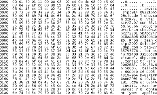
Figure 18-1. VoIP packet shown in data dump format
Figure 18-1 shows a packet, in both hex and ASCII. In network analyzers of years past, this is what we often had to decipher by hand to determine the construction of the packet. The above packet is flowing across an Ethernet interface and as such we can start with decoding the MAC addresses (00:01:30:01:11:00 and 00:08:02:e4:0b:dc) which leads us to the 0800 which identifies the next layer as IP immediately following the 14-byte Ethernet II header. Given that we can see that the upper nibble of the next byte, 4 in 45, this represents that it is an IPv4 header. This continues all the way through the packet, based upon knowing, in detail, numerous RFC's. Imagine if, to get anything done, one had to do all this work every time. Instead, in packetC, it is presumed those standard layers 2 through 4 headers are decoded by the operating system with the decoded information presented to the application in the pib. For non-standard headers or those not recognized by the operating system, pib values will highlight what is not recognized. Not only will the types be presented, but offsets to each layer will be provided when the headers were decoded so that standard descriptors, provided in protocols.ph, can be referenced such that the packet can be reference fields in the headers directly shown by name, much like “tree view” in the packet decode shown in Figure 18-2.
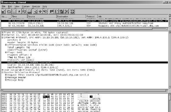
Figure 18-2. Ethereal screenshot of VoIP packet decode
In modern packet analyzers, packets are decoded by the analyzer allowing the network engineer to view the packets not only in the original hex and ASCII but also in a “tree view” and “column view” shown in the upper two sections of Figure 18-2. By leveraging the values for layer offsets provided in the pib in combination with descriptors defined either by the system, such as those in protocols.ph, or the application, packetC allows direct access to fields as though they were simple elements of a structure. While each packet may have a slightly different construction with optional elements in headers, the descriptors floating at layer offsets allow for compensation as well as the advantage of not needing to even inspect lower layer headers if only upper layers are of interest. In other words, if an application is performing Access Control List functionality using the IP and TCP headers, whether Ethernet or SONET or even MPLS is present becomes irrelevant as layer 3 and layer 4 offsets should already be present.
Figure 18-3. WAN packet as ordered set of headers and payload
A logical view of a packet often held by developers is something like that shown in Figure 18-3. The goal of the pib is to help transition the ever-changing form of the current packet into a simple method of accessing it representing more of the logical view.
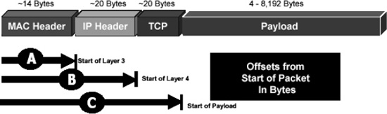
Figure 18-4. Ethernet LAN packet with pib offsets highlighted
In packetC, decoding of packets is accomplished through the combination of both the decoded information present in the pib along with descriptors. Given that most of the complexity remains in the descriptors, the pib can remain quite simple, needing only to provide three elements: layer offsets, decoded layer types and integrity information. A pib's values are unique to the current packet being processed and as such the layer offsets map to the current packet only as one packet versus another that may have optional elements that change the offsets. The common layer offsets being referenced in the pib are shown as A, B, and C in Figure 18-4, where A represents pib.l3Offset, B represents pib.l4Offset, and C represents pib.payloadOffset.
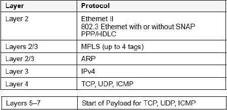
Figure 18-5. packetC pib layer offset designation
Figure 18-5 shows a mapping of common network protocols to an OSI stack influenced by packetC layer designations is shown. Within packetC there is no layer 2 offset specified, as this is always 0 for packetC which addresses layer 2 through 7 network processing. The payload offset is often called layer 7 and contains headers for protocols such as DNS, BGP, and HTTP. From an OSI perspective this should be layer 5, however, TCP/IP combines what would have been layer 5-7 into one layer, commonly referred to as layer 7. While headers in layers 2-4 don't change much, these can often be defined by standard include files and don't need to be extended very often in packetC development. By contrast, application-layer protocols are vast and this often becomes the realm of complex packet descriptor construction and conditional logic being required to process them in packetC. As such, layer 7 headers are left outside the scope of most pre-defined system includes, in particular due to the fact that many layer 7 headers in TCP/IP don't follow simple binary construction patterns but rather often rely on text-based protocols, such as the SIP example shown earlier.
Layer offsets help determine where something like an IP header sits, as is the case with pib.l3Offset. The next step is to determine what descriptor to use, for example, an IPv4 one or an IPv6 one. That is where the types come in such as pib.l3Type with values L3TYPE_IPV4 or L3TYPE_IPV6 helping denote the above two versions. At that point, the only other key element is determining if integrity of the header can be relied on, which is where the flags come into play, such as pib.flags.l3CheckSumValid. If the layer 3 header checksum isn't valid, then there is no way to know that the decoded type is appropriate. This complex calculation and validation is presumed to be implemented by the operating system with the result presented to the packetC application for the current packet in the pib. One of the simplest means of ensuring that the pib data can be trusted for TCP/IP processing is checking the l4CheckSumValid bit as it implies TCP, UDP, or ICMP in layer 4 and that the IP header has a valid layer 3 checksum plus proper construction and layer offsets all the way to the Ethernet or SONET header. Placing a comparison early in an application such as the following can save a lot of work in processing by allowing code to move into field analysis and exception handle the small amount of non-TCP/IP traffic coming through the system.
// Throw exceptions if not expected packet types.

if (pib.l4Type != L4TYPE_TCP) throw …
Refer to the descriptors chapters for more details on decoding headers using pib values.
PacketAction action;This is the action specified by the packetC application to be performed on the packet at the completion of processing, namely FORWARD or DROP as determined by the PacketAction enumeration.
int length;This is the actual length of the packet as received by the operating system. It should be equivalent to the derived total length of the packet from decoding headers, however, it doesn't necessarily need to be for bogus or otherwise fragmented packets. The value in sys.length is useful for performing quick checks to determine if a packet is one with content that may be of interest or not.
bits int

{

    replica           : 1;

…

} flags;
This field identifies that the current packet is not one received from a network interface, but rather one created by a packetC application. This is often useful for discerning packets which represent events, such as background thread workloads, versus those that are actual packets.
bits int

{
…
l3CheckSumValid : 1;
l3CheckSumRecalc : 1;
l4CheckSumValid : 1;
l4CheckSumRecalc : 1;
…
} flags;These bit fields identify whether protocol decode procedures in the operating system determined that the current packet's layer 3 and layer 4 protocols have valid checksums. Based upon the protocol decoded, this information may or may not be relevant. Recalc variants represent requests to the operating system to recalculate the checksum after processing of the current packet has completed which is useful to offload this processing required for packets being modified.
bits int

{

…

    ipFragment   : 1;

    ipv4         : 1;

    ipv6         : 1;

…

    mpls         : 1;

    vlan         : 1;

    pad          : 18;

} flags;
The bit fields shown above are a collection of descriptive references to the currently decoded packet's protocols. The ipv4 and ipv6 flags denote which version an IP header is, no different than directly inspecting the upper nibble of the first byte of an IP header. The ipFragment field represents whether or not the current IPv4 or IPv6 packet is fragmented while mpls and vlan represent whether or not these tags are present in the current packet. As always, “pad” is a reserved keyword for unused bits in a bit field leveraged to assure the bit field is properly aligned.
L2Type l2Type;

L3Type l3Type;

L4Type l4Type;
The layer type fields store the decoded type of each layer 2, 3, and 4 header using the enumerations specified by the type declarations presented in the shared definitions section above. For example, pib.l2Type may be set to L2TYPE_ETHII when the current packet contains a standard layer 2 Ethernet II header. Determinations for types are made based upon the underlying operating system following a protocol header decode procedure similar to those shown at the end of this chapter.
These represent the offsets of each protocol layer in the packet, i.e., the number of bytes from the start of the packet. These values are determined through the decoding of the packet per the protocol decode procedures shown later on in this chapter. The descriptors provided in the system include file protocols.ph leverage these values for alignment of standard header decodes mapped onto the packet.
In packetC, all values are by default 0. If a protocol is properly decoded, the value will be updated with the appropriate non-zero value for the protocol layer offset. It is critical that a packetC application verify that fields are non-zero or properly decoded, such as ensuring ipv4 and l4CheckSumValid bits are set before using pib.l4Offset in the application.
bits int

{

…

    logAccelReplicate : 1;

    // After transmit, shall Log Accelerator replicate current packet?

    // 0=False, 1=True.


    logAccelModify    : 1;

    // After transmit, shall Log Accelerator modify current packet?

    // 0=False, 1=True.


    logAccelMethod    : 1;

    // Log Accelerator Method of Round Robin (0) assignment

    // or specified target.


    logAccelDatasize  : 1;

    // If set (1), replicated packets will only contain

    // 64 bytes of payload.

…

} flags;

int  logAccelTarget;  // Specifies the Log Accelerator rule number to

use if logAccelMethod set.
The last list of fields above are CloudShield-specific attributes in the cloudshield.ph file related to target blade capabilities present on a limited variety of CloudShield systems. Please refer to Log Accelerator user guides for details on these attributes. In general, these are used to communicate information to a post-processor to packetC about traffic management rules that are to be used to process, potentially replicating, and modify the packet upon transmission.
System Information ($SYS sys)
The System Information (SYS) type is a structure that contains attributes useful for processing a packet that describes attributes of the system or treatment of packets, but not the contents or construction of the packet. For example, this includes time data, parallel processing context, the port where the packet was received, and information about system thresholds, such as buffer utilization.
System Information is accessible to the user in a variable of the predefined type, $SYS, specified as an argument to the packet module main. It is always referenced in packetC as sys and this predefined type cannot be used to declare other types.
void main ($PACKET pkt, $PIB pib, $SYS sys ) {…}
The structure definition for $SYS is declared in a target system include file or predefined by a packetC compiler. For CloudShield systems, $SYS is defined in the cloudshield.ph include file.
The structure of the System Information Block ($SYS) is shown below:
//==============================================================================

//  System Information

//

//  The typedef for structure $SYS is instantiated as sys and delivered as a

//  parameter to main() containing information about the current system.

//  The system information structure, sys, acts as both a source of information

//  about the system the packetC is operating on as well as system level

//  that may affect choices in processing.  In particular this structure

//  data about the physical interface packets were received on an whether this

//  is an Ethernet or SONET system.  Some attributes may affect the system's

//  processing of operations as well as provide real-time information about the

//  system that may change during the processing of a packet.

//

//  This release (v1.01) of cloudshield.ph introduces UTC time support.  Note

//  the change of the old xtime(now ticksL in struct time) and time(now ticks).

//

//==============================================================================

struct $SYS

{

  int           messageId;

  MessageGroup  messageGroup;

  int           inPort;

  int           outPort;

  int           context;

  int           ticks;

  struct Time64Values {

             Time64 ticksL;

             Time64 utcTime;

             Time64 utcTimeUncorrected;

             Time64 utcTimeDrift;

             } time;

  int           bufferCount;

  int           queueDepth;

  int           logFailures;

  bits int

  {

    sonet : 1;

    pad   : 31;

  } flags;

  int           requeueCount;

  int           tcsFlow;
  int           tcsRule;

  int           outBlade;

  int           inBlade;

  int           replicatePort;

  int           replicateBlade;

};
Many components of the sys structure depict information about the underlying system packetC applications are running on or information regarding the flow of the current packet through the system. In addition, fields are present that are utilized by operators and actions in packetC for control-plane interaction. Refer to specific chapters on these features for a detailed explanation and to the section below for a brief synopsis of each field.
int messageId;

MessageGroup  messageGroup;
When interacting with the control-plane through the alert and log commands, a number of parameters may be necessary for providing some associated data along with the data contents being presented to the control plane. Unique predefined messages by an application, stored in the control plane, referenced by the data plane, have their reference value placed in messageId while the group, essentially a severity, is referenced by the messageGroup field. All future alert and log commands will use the currently set value by the application until these values are changed. If these values are not important to the logging of data, as is often the case when logging packets, these fields in the sys structure can remain at their system startup defaults.
int       inPort;

int       outPort;
Every packetC application is treated as a virtual appliance with as many interface ports as desired by the application developer. When deployed upon a system, these ports are bound either to interfaces on other virtual appliances or to physical interfaces on the system. These two fields in sys represent the interface through which the current packet arrived, and upon the interface through which the packet shall be forwarded upon completion of processing, respectively. Based upon external provisioning choices these interface ports may or may not equate to physical ports.
int context;In packetC, generally many more than one packet is being processed at any given point in time. There are many cases, such as performance modeling, where view into the current context number that the operating system has assigned the current packet being processed is needed. This value is stored in sys.context.
int     ticks;

struct Time64Values {

           Time64 ticksL;

           Time64 utcTime;

           Time64 utcTimeUncorrected;

           Time64 utcTimeDrift;

           } time;
The structures above represent time values based upon derivatives of the system 64-bit “CPU tick timer.” Multiple different representations of time may appear in sys based upon the target platform's support features. The integer ticks is the lower 32 bits of the system tick timer used for fine-grained delta measurements. The time structure contains four instantiations of a 64-bit time value. Some systems may not support all representations in this structure. At the highest level, systems generally have a 64-bit “CPU tick timer” which is representative of an oscillator. In most systems, this timer is instantiated to be ticks since UTC (1/1/1970 00:00:00 GMT), however, drift is never adjusted and using it for UTC is not viable nor expected to be very accurate. The ticksL represents a 64-bit value containing this hardware tick count and is specific to the hardware. The lower 32 bits of ticksL is the same as ticks. The ticksL value is not corrected for UTC, however, it can be utilized for measuring long-term response times on an accurate basis, nominally with 10ns per increment of the value. The three 64-bit values of utcTime, utcTimeUncorrected, and utcTimeDrift are in the form of two 32-bit values representing seconds and microseconds. These values are based upon network time protocol (NTP) drift-adjusted values such that the utcTimeUncorrected is based upon a boot time setting of UTC time but without any adjustment to drift over time. The utcTime value is as accurate as the system can perform with its time adjusted by the measured drift as determined from NTP updates. Different systems can vary, from the most accurate GPS based NTP sources accurate to 50 microseconds while most systems operate in the few milliseconds on a LAN to 10 or more milliseconds in a WAN. The utcTimeDrift value is provided to the packetC application to present a window into the current drift adjustment. The utcTimeDrift is the absolute value of correction to the time required to convert utcTimeUncorrected into utcTime. Determining the sign of this value is possible through comparing the corrected and uncorrected time. The utcTime value should be equivalent to the utcTimeUncorrected modified by the utcTimeDrift. Note that these are synchronized with one another only when the structure time is read in a single assignment of the entire structure because values change frequently.
The value for ticks will roll over on average in less than 1 minute while ticksL should not roll over within our lifetimes. As an example, on 1.4GHz systems with a tick increment every 16 clocks, a tick increments every 11.428 nanoseconds. This results in ticks rolling over every 48 seconds while ticksL will take over 6,000 years. For UTC values, these are stored in seconds and microseconds. By definition, the lower 32-bit microseconds value will roll over every 1,000,000 microseconds and result in an increment to the upper 32-bit seconds value. With UTC based at 1970 and since it takes more than 136 years for the seconds value to roll-over, there should not be any issues in the 64-bit approach to UTC until 2106.
int      bufferCount;    // Number of Free Packet Buffers

int      queueDepth;     // Number of Packets Waiting To Be Processed
As packets are received by the underlying operating system, they are placed into a buffer. Each context is assigned one packet to process and upon completion retrieves the next one to process. In cases of over-subscription of the processing power of a system executing the packetC application, a developer may desire to adjust the amount of processing done per packet based upon the quantity of packets waiting to be processed. The sys.bufferCount value represents the number of packet buffers consumed by those waiting to be processed, in processing, and awaiting transmission. Compare this value against a constant containing a maximum for the target platform to determine percentage of buffers in use. The sys.queueDepth identifies the number of packets awaiting to be processed. This value does not include those currently assigned to contexts or those awaiting transmission that a packetC application will not see again.
int    logFailures;   // Number of Failed Log Attempts Due To System

Overload
Provides feedback for when the log and alert commands are overloading the control plane. As the data plane where packetC is executing may often have more processing power than a control plane, it is important in applications that perform heavy logging to ensure that they do not overload a given system. Refer to target platform references for the number of logging functions per second that can be sustained.
bits int

{

  sonet : 1;

  pad   : 31;

} flags;
The physical layer-1 interface of a system is important as it pertains to identifying certain types of capabilities with regard to point-to-point network links versus those in layer 2, such as Ethernet, that can leverage switching. Bit fields in sys are provided to inform the application whether it is on a SONET or Ethernet system. By default, packetC systems presume an Ethernet environment unless bits are set for an alternate physical transmission medium, such as SONET identified by the bit field above.
int requeueCount;Each time a packet is placed on the queue to postpone further processing until a future time, the sys.requeueCount field is incremented. packetC code is able to place packets back into the input queue through the PacketAction field within the pib. This can be used to prevent packets from a continuous requeue loop by providing an escape for the evaluation condition.
int    tcsFlow;

// 32-bit value containing the hash of the

// flow tuple from TCS pre-processor


int    tcsRule;

// Rule # which matched current packet in TCS pre-processor


int    replicatePort;

// Log Accelerator replicated packet physical port number


int    replicateBlade;

// Log Accelerator replicate packet blade number in dual-blade scenarios
int outBlade;
// Output can specify peer-blade in DPPM-800 systems,
// 0=current, 1=other
int inBlade;
// Input can come in alternate blade in DPPM-800 systems,
// 0=current, 1=other.The last list of fields above are CloudShield-specific attributes in the cloudshield.ph file related to target blade capabilities present on a limited variety of CloudShield systems. Please refer to Traffic Control System (TCS) user guides for details on these attributes. In general, these are used to communicate information from a pre-processor to packetC about traffic management rules that were used to classify the packet flow. In addition, choices by the packetC application to request post-processing of the packet, such as replicating it and sending copies to different blades, is controlled by these values.
TCP/IP Stack Decode for pib Layer Offset Calculations
A variety of Internet RFC's describe the various protocols and the meaning of different fields that can appear in layers 2 through 4 of TCP/IP systems. Unfortunately, putting these all together to make a simple method of decoding a packet can be quite elusive. Further complicating things is interpreting results, like the values in pib and sys, when assumptions are not clearly understood. As such, each target platform should define the process through which a packet is decoded from a byte stream into the fields present in the pib. Example flow charts for basic layer 2 through 4 network headers are shown below.
Layer 2 Ethernet Header Decode Procedure
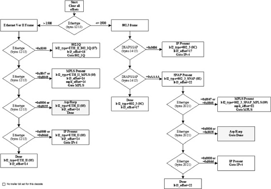
Figure 18-6. Layer 2 Ethernet Header Decode Procedure
Figure 18-6 shows how offsets are computed for Ethernet and which protocols are valid for layer 3 and layer 4. Boxes with “Goto <name>” represent jumps to other flow charts below.
The Layer 2 Ethernet Header Decode Procedure examines the packet data to determine the layer 2 (L2), layer 3 (L3), and layer 4 (L4) information contained in the packet. The L2, L3, and L4 headers, if present, are decoded, determining the type and location of each header in the packet. The flow chart illustrates the decision process for each packet that is performed by the operating system prior to delivery of the packet to packetC. The L2 decode is the first process performed. Once the initial L2 procedure has been completed, the packet may undergo further L2 processing if the packet is 802.1Q-encapsulated or contains an MPLS header. If no further L2 processing is required and the packet is an IPv4 packet, the IPv4 (L3) header checksum is verified. If the L3 checksum is valid, L4 processing of the IPv4 and IPv6 decode procedure proceeds to a subsequent layer 4 flow chart. If the packet is 802.1Q-encapsulated, the 802.1Q Layer 2 decode procedure is followed before any L3 or L4 processing can proceed. The 802.1Q processing is similar to the Ethernet decoding procedure since 802.1Q is an encapsulation protocol.
Layer 2 Ethernet 802.1Q (VLAN) Decode Procedure
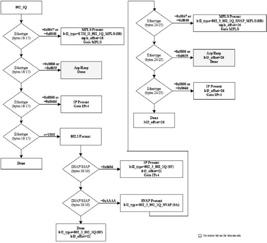
Figure 18-7. Layer 2 Ethernet 802.1Q (VLAN) Decode Procedure
The flow chart shown in Figure 18-7 is processed only for Ethernet packets that were identified with a value of 0x8100 in the Ether Type. Unless the Layer 2 Ethernet Header Decode Procedure jumps to this flow chart, it will be ignored. Packets with one or more VLAN headers, specified in IEEE standard 802.1Q, will be decoded using this procedure. As a result the L2 header is larger, increasing the value of pib.l3Offset, and modifying the pib.l2Type value.
Layer 2 SONET Header Decode Procedure
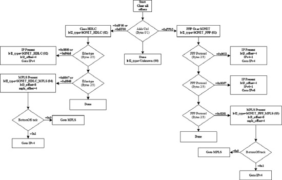
Figure 18-8. Layer 2 SONET Header Decode Procedure
In the WAN, packets often traverse links that are not Ethernet-based. As a result, the layer 2 headers do not conform to Ethernet decodes shown in previous procedures but rather follow PPP or HDLC formats in most cases. The procedure shown in Figure 18-8 reflects the generalized process for decoding these common headers in SONET systems and the process by which the next layer headers are determined.
Layer 2 ½ MPLS Label Stack Decode Procedure
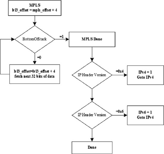
Figure 18-9. Layer 2½ MPLS Label Stack Decode Procedure
If the Ethernet or SONET packet contains an MPLS header, the label stack is processed as shown in Figure 18-9. MPLS label stacks can encapsulate a variety of protocols in them. As such, the entire stack must be evaluated to determine not only how many bytes are between the layer 2 header and the commonly-encapsulated layer 3 header, but also to determine whether MPLS is encapsulating IP or not. The flow chart above shows a simple evaluation of MPLS where the bottom of stack bits in the MPLS label are looked for and the next uses some simple evaluation to identify the version of IP header.
Layer 3 IPv4 and IPv6 Header Decode Procedure
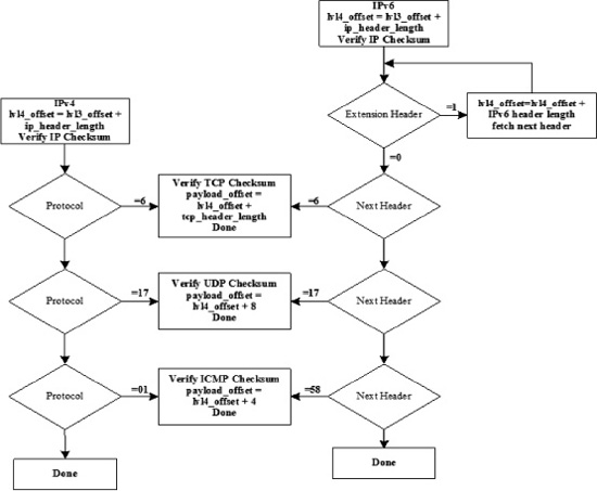
Figure 18-10. Layer 3 IPv4 And and IPv6 Header Decode Procedure
If the packet contains an IPv4 or IPv6 header, the procedure shown in Figure 18-10 will be employed to determine the L4 type of the packet as well as computation of layer 3 integrity when the L3 header is an IPv4 header. If the L4 header is TCP, UDP, or ICMP, the L4 checksum is also verified.
A packet validation failure in one layer prevents higher layer processing from occurring. If the L2 CRC fails, the L3 checksum is marked invalid. A packet with an L2 CRC error is currently dropped before any processing. If the L3 checksum verification fails, the L4 checksum is marked invalid and the L4 type is set to “UNKNOWN.”
The checksum for UDP is optional in IPv4 and, if missing, is indicated by setting the checksum field to 0x0000. CloudShield systems handle this situation and mark the packet as being IPv4 and UDP with a valid checksum (optional checksums being considered valid). References for each vendor and target need to be evaluated for these types of corner-cases before presuming what some of the pib values imply. For TCP and ICMPv4, however, the checksum is not optional and a checksum value of 0x0000 is considered valid. If an IPv4 packet is received with an invalid L4 checksum, the packet is still marked as being IPv4 and UDP (for example), however, the L4 checksum valid bit is not set. Just because a packet has a bad checksum doesn't invalidate the packet format. The same is true if the L3 checksum is invalid. The L3 type is still set to IPv4 and the L3 checksum valid bit is not set. For fragments, the situation is a bit more complicated. As an example, if an IPv4/UDP fragment is received, the packet is marked as an IPv4 packet, UDP, fragment packet with the L4 checksum valid bit cleared. For the first packet in the fragment, the pib.payloadOffset field is set correctly, however, for every subsequent packet the payload offset is set to 0x0000. A packetC application must handle reconstruction of fragmented packets and determine integrity.
For Layer 4 Header Decode Procedures for TCP, UDP, and ICMP follow the same form of mechanism shown above and are equally complex as optional header extensions can appear adjusting the distance from pib.l4Offset to pib.payloadOffset.
Example cloudshield.ph Include File
Note that by design, most of cloudshield.ph is commented out as the types and structures defined herein are built into the tool-chain. This file does include some uncommented sections and is useful to ensure application code contains a clear definition for all structures and their form presumed during code audits. Furthermore, guard macros ensure that packetC applications are tied to the correct form of these types and structures.
//==============================================================================

//  cloudshield.ph - packetC standard include for CloudShield platforms.

//

//    This packetC standard include file defines platform specific structures

//    related to intrinsic functionality within the language.  In addition,

//    structures and data types that are built into the compiler are provided

//    in this document as comments to enable programmers to understand and

//    validate types.

//

// author

//    [email protected]

//

// copyright notice

//    © 2009 CloudShield Technologies, Inc.

//

//==============================================================================

#ifndef CLOUDSHIELD_PH

#define CLOUDSHIELD_PH

#define _CLOUDSHIELD_PH_VERSION 1.01

#define __PACKETC__ TRUE

//==============================================================================

//  PacketAction Enumerated Type

//

//  Used with action in $PIB to define what to do with packet at end of main().

//

//==============================================================================

// enum int PacketAction

// {

//   DROP_PACKET    = 0,

//   FORWARD_PACKET = 1,

//   REQUEUE_PACKET = 2

// };
//==============================================================================

//  Layer Type Enumerations

//

//  L2Type, L3Type and L4Type are used by the $PIB to describe current packet.

//

//==============================================================================

// enum int L2Type

// {

//   L2TYPE_OTHER                  = 0,

//   L2TYPE_SONET_PPP              = 1,

//   L2TYPE_SONET_HDLC             = 2,

//   L2TYPE_SONET_HDLC_PPP_MPLS    = 17,

//   L2TYPE_SONET_HDLC_MPLS        = 18,

//   L2TYPE_ETHII                  = 3,

//   L2TYPE_ETHII_MPLS             = 19,

//   L2TYPE_ETHII_8021Q            = 35,

//   L2TYPE_ETHII_8021Q_MPLS       = 51,

//   L2TYPE_802_3_SNAP_MPLS        = 21,

//   L2TYPE_802_3_SNAP_802_1Q      = 37,

//   L2TYPE_802_3_SNAP_802_1Q_MPLS = 53,

//   L2TYPE_802_3                  = 4,

//   L2TYPE_802_3_MPLS             = 20,

//   L2TYPE_802_3_SNAP             = 5,

//   L2TYPE_802_3_802_1Q           = 36

// };

//

// enum int L3Type

// {

//   L3TYPE_OTHER = 0,

//   L3TYPE_IPV4  = 1,

//   L3TYPE_IPV6  = 2,

//   L3TYPE_ARP   = 3,

//   L3TYPE_RARP  = 4,

//   L3TYPE_IPX   = 5

// };

//

// enum int L4Type

// {

//   L4TYPE_OTHER  = 0,

//   L4TYPE_TCP    = 1,

//   L4TYPE_UDP    = 2,

//   L4TYPE_ICMP   = 3,

//   L4TYPE_ICMPV6 = 4,

//   L4TYPE_ESP    = 5,

//   L4TYPE_AH     = 6,

//   L4TYPE_GRE    = 7,

//   L4TYPE_SCTP   = 8

// };


//==============================================================================

//  Packet Information Block

//
//  The typedef for structure $PIB is instantiated as pib and delivered as a

//  parameter to main() containing information about the current packet.

//  The pib acts as both an input structure as well as the end state of the pib

//  determines actions to be taken against the packet at the end of main().

//

//==============================================================================

// struct $PIB

// {

//   PacketAction  action;

//   int           logAccelTarget;

//   int           length;

//   bits int

//   {

//     replica           : 1;

//     l3CheckSumValid   : 1;

//     l3CheckSumRecalc  : 1;

//     l4CheckSumValid   : 1;

//     l4CheckSumRecalc  : 1;

//     ipFragment        : 1;

//     ipv4              : 1;

//     ipv6              : 1;

//     logAccelReplicate : 1;

//     logAccelModify    : 1;

//     logAccelMethod    : 1;

//     logAccelDatasize  : 1;

//     mpls              : 1;

//     vlan              : 1;

//     pad               : 18;

//   } flags;

//   L2Type              l2Type;

//   L3Type              l3Type;

//   L4Type              l4Type;

//   int                 l2Offset;

//   int                 mplsOffset;

//   int                 l3Offset;

//   int                 l4Offset;

//   int                 payloadOffset;

// };


//==============================================================================

//  Message Group Levels

//

//  The MessageGroup enumerated type is used to set a severity level for a log()

//  message.  This field can be set once in a context and all future events that

//  are generated during the processing of the packet will utilize this value.

//  The $SYS structure utilized MessageGroup with field messageGroup.

//

//==============================================================================

// enum int MessageGroup

// {

//   MSG_CRITICAL = 1,

//   MSG_MAJOR    = 2,
//   MSG_MINOR    = 3,

//   MSG_WARNING  = 4,

//   MSG_INFO     = 5

// };


//==============================================================================

//  Message Constants

//

//  The following constants provide a maximum message number and length for a

//  log() message generated by the packetC system.  Use in conjunction with the

//  messageId field in $SYS.

//

//==============================================================================

// const int MAX_PACKETC_MSGS    = 255;

// const int MAX_PACKETC_MSG_LEN = 80;


//==============================================================================

//  Time Construct Structure

//

//  This structure is used to represent the 64-bit fields used in time elements

//  of the $SYS structure.  For ticks this is the upper and lower 32-bits of a

//  64-bit counter.  For UTC Time values, this relates to the seconds (high) and

//  microseconds (low) since UTC (1/1/1970) in a single 64-bit structure.

//

//  This structure replaced XTime structure from cloudshield.ph version 1.00

//

//==============================================================================

// struct Time64 {

//   int highOrder;

//   int lowOrder;

// };


//==============================================================================

//  System Information

//

//  The typedef for structure $SYS is instantiated as sys and delivered as a

//  parameter to main() containing information about the current system.

//  The system information structure, sys, acts as both a source of information

//  about the system the packetC is operating on as well as system level

//  that may affect choices in processing.  In particular this structure

//  data about the physical interface packets were received on an whether this

//  is an Ethernet or SONET system.  Some attributes may affect the system's

//  processing of operations as well as provide real-time information about the

//  system that may change during the processing of a packet.

//

//  This release (v1.01) of cloudshield.ph introduces UTC time support.  Note

//  the change of the old xtime(now ticksL in struct time) and time(now ticks).

//

//==============================================================================

// struct $SYS

// {

//   int           messageId;
//   MessageGroup  messageGroup;

//   int           inPort;

//   int           outPort;

//   int           context;

//   int           ticks;

//   struct Time64Values {

//              Time64  ticksL;

//              Time64  utcTime;

//              Time64  utcTimeUncorrected;

//              Time64  utcTimeDrift;

//              } time;

//   int           bufferCount;

//   int           queueDepth;

//   int           logFailures;

//   bits int

//   {

//     sonet : 1;

//     pad   : 31;

//   } flags;

//   int           requeueCount;

//   int           tcsFlow;

//   int           tcsRule;

//   int           outBlade;

//   int           inBlade;

//   int           replicatePort;

//   int           replicateBlade;

// };


//==============================================================================

//  Search Results Structure

//

//  When a match or find operator is used on a search set, a structure is then

//  returned with the result.  This structure is the typedef for that result.

//

//==============================================================================

// struct SearchResult

// {

//   int   index;

//   int   position;

// };


//==============================================================================

//  Exception Constants

//

//  Try catch based exception handlers are core to packetC.  There are a set of

//  pre-defined exceptions for intrinsic operators to packetC.  The section

//  of exception constants below are what is implemented in the associated

//  packetC compiler.

//

//==============================================================================

// typedef int Exception;

// const Exception              ERR_ANY_EXCEPTION   = 0;
// const Exception              ERR_DB_FULL         = 1;

// const Exception              ERR_DB_READ         = 2;

// const Exception              ERR_DB_NOMATCH      = 3;

// const Exception              ERR_PKT_INSERT      = 4;

// const Exception              ERR_PKT_DELETE      = 5;

// const Exception              ERR_PKT_NOREPLICATE = 6;

// const Exception              ERR_SET_NOMATCH     = 7;

// const Exception              ERR_SET_NOPERFORM   = 8;

// const Exception              ERR_SET_NOTFOUND    = 9;

// const Exception              ERR_PKT_NOTREQUEUED = 10;


//==============================================================================

//  User Defined Exception Constants

//

//  packetC users can create their own exceptions constants to throw by using

//  the ERR_LAST_DEFINED constant.

//

//  const Exception   ERR_MY_EXCEPTION  = ERR_LAST_DEFINED + 1

//

//==============================================================================

// const Exception              ERR_LAST_DEFINED    = 64;


//==============================================================================

//  Packet Type

//

//  Each system may have a slightly different constraint on the buffer for each

//  packet.  The typedef below defines the $PACKET for the system.

//

//==============================================================================

// typedef byte $PACKET[9 * 1024 - 1];


//==============================================================================

//  Truth Constants

//

//  In packetC no boolean types exist, however, true and false are pre-defined.

//  To enforce consistency and strict type matching, bool is defined.

//

//==============================================================================

// const int true  = 1;

// const int false = 0;

typedef int bool;

//==============================================================================

//  Search Set Constants

//

//  Null is a valid value in strings and regular expressions.  Constants are

//  pre-defined for these values.

//

//==============================================================================

// const byte NULL_STOP[1]  = "x00";

// const byte NULL_REGEX[4] = ".*?x00";


#endif