
![]()
Working with Objects
Seeing your 3D printer generate objects is really cool. When you create solutions and things you can use every day, the experience is even greater. However, there is more to 3D printing than just downloading and printing things. Indeed, most things on Thingiverse can be downloaded and printed with no changes. However, sometimes you need the same thing, only with a hole in a different place or maybe a bit longer or wider.
Also, most things you print can be used with little or no work, but some things will require trimming, reaming out holes, and so forth. If you are creating things for decoration or personal wear, you may want the surface to be perfectly smooth or at least without the telltale layering effect. You may even want to change the color of your thing. That is, you may not have the right color filament, or the color of the filament just isn’t the right shade.
I address all of these topics in this chapter. I begin with a short tutorial on how to create your own objects (it’s really easy), I next discuss how to make modifications to existing objects (sometimes called a mashup) and joining multipart objects, and then I discuss various techniques for completing your object by applying finishing touches.
Creating Objects
If you haven’t used Thingiverse by now, you really should give it a try. You will find many thousands of things that you can download and print. If you have used Thingiverse or a similar web site, chances are you have already printed a number of objects that others have created. However, sometimes the right thing just isn’t out there on Thingiverse. Perhaps you can find something similar, but it just isn’t quite right—maybe it’s too long or the bore holes are the wrong size or in the wrong place.
Wouldn’t it be great if you could create your own object or modify objects uploaded by others? The short answer is you can! But it will depend on what CAD software was used to create the object and the format of the object file. If you have experience with the CAD that was used to create the object, that’s great and you can do whatever you want to make the object your own.
However, if you have little or no experience with the specific CAD software, what can you do? Fortunately, you are not alone and there is a solution. Indeed, a lot of enthusiasts don’t have extensive knowledge in CAD software and yet they have created a lot of objects on Thingiverse. How did they do it? They used a much simpler, easier-to-use object creation software called OpenSCAD (openscad.org).
Recall from an earlier chapter that OpenSCAD uses a programming-like environment to generate a script that can be compiled to render the object. But don’t let the programming element discourage you. You don’t have to have an advanced degree in computational sciences to learn how to use OpenSCAD.1 In fact, all you need to create objects in OpenSCAD is the ability to envision an object as a step-wise build. That is, you will be using commands (shape primitives and controls) to generate an object from several other parts.
Let’s dive into a short tutorial on OpenSCAD. The following won’t give you magical powers, but it will get you everything you need to start making your own objects in OpenSCAD. I present the most basic things that you need to know to get started with OpenSCAD. I encourage you to download OpenSCAD (openscad.org/downloads.html) and experiment with the code presented in the tutorial.
OpenSCAD Tutorial
OpenSCAD is an amazing tool for those of us who want to create our own objects, but don’t have the time to master a complex CAD application. OpenSCAD uses a relatively small number of commands (called statements) that you can use to build an object in a programmatic way. The files you create therefore are code files (plain text) that are very small compared to most CAD application binary object files. Indeed, I have seen some files from popular CAD applications that were quite large. Perhaps the best quality of OpenSCAD is that it is open source and supported by a growing community of enthusiasts.
You may be surprised by the number of objects that are available on Thingiverse as OpenSCAD files. I did a quick query and found over 3,000 things that mention .scad2—and that’s just searching on the title! So there are plenty of examples out there. We typically save OpenSCAD (or simply SCAD) files with the extension .scad.
Before jumping in, let’s consider one of the key concepts you must master to get the most out of OpenSCAD: coordinates.
Coordinates
One of the biggest challenges to coding your own objects is keeping a sense of the orientation of the object in the coordinate system. We are working in three-dimensions. The OpenSCAD-rendered object screen has a diagram or key to show you the orientation of the axes. Figure 12-1 shows the key.

Figure 12-1. Coordinate key in OpenSCAD
When you render (compile) your object (code), you will see the result on the right side of the OpenSCAD dialog. The default orientation has the X axis left-to-right, the Y axis front-to-back, and the Z axis up-and-down. You can zoom and rotate the object to see all sides. The key for the axes moves with the object, so you can always keep the perspective.
However, sometimes it can be confusing as to which parameter you want to change or set in some of the code statements. Fortunately, most statements that use coordinates as parameters list them by X, Y, and Z. As long as you keep that in mind, you can provide the right parameters. If you make a mistake, it will be rather obvious when you compile the code. For example, if you wanted an object 20mm wide (on the X axis), 10mm long (on the Y axis), and 40mm high but reversed the X and Y parameters, you would see the object is 10mm wide and 20mm long instead.
![]() Note All measurements in OpenSCAD are unitless, but when you export the STL, the 3D software will interpret the units as millimeters.
Note All measurements in OpenSCAD are unitless, but when you export the STL, the 3D software will interpret the units as millimeters.
Since the result is a compilation of the code, all you need to do is fix the parameters and recompile. I encourage you to experiment with the cube() statement to see how the axes are oriented. Recall the cube() statement is one of several primitive solid statements that take the coordinates as a list specified by square brackets. The following shows the correct code for the example.
cube([20,10,40]);
I have already shown you a very simple code file for creating a simple shape. The following shows another small example that creates a small object made from two parts. Figure 12-2 shows the OpenSCAD environment with the code pane on the left, an object view on the right, and a feedback area in the lower right.

Figure 12-2. Object in OpenSCAD
The object is a hammer in its most basic design—a large block for the head and a tall cylinder for the shaft. Notice the code. Here I used a cube object to create the head and a cylinder for the shaft (or handle). The one command that may seem strange is the translate() statement. It is one of several transformation statements that allow you to change the origin or starting point for the object. The default starting point is the center (0,0,0) position. If I had not used the translate() statement, the shaft would have been placed in the wrong location.
The use of translate() also shows how you can combine graphic operations with shape statements. That is, the translation is executed for the next statement (or shape). Notice that the cylinder() statement, which is another primitive solid statement, that takes three parameters. In order, they are height, radius of the base, and radius of the top. If you’re thinking, hey, that means I can create a cone, you’re right, you can.
One feature that is not commonly used is the ability to specify the parameters by name. For example, I could have used the following to code the cylinder for the shaft.
translate([15,10,20]) cylinder(r1=5,h=50,r2=5);
Notice that here I specified the parameters out of order. So long as you reference them by name, you can put the parameters in any order. If you do not reference them by name, you must put them in the order that is listed in the documentation.
Notice also that each statement is made up of one or more statements and must end (terminate) with a semicolon. There are statements that don’t use a semicolon for a terminator, but those are things like code blocks and modules (as we will see later).
So how do you know which statements are available and how to specify the parameters? There is a good set of documentation on the OpenSCAD site that you should spend some time exploring (openscad.org/documentation.html). What I present here in this tutorial will get you going, but there is much more to OpenSCAD. That is, there are many more statements available from 2D shapes, 3D shapes, Boolean operations, and many other graphics operations.
![]() Tip There is a cheat sheet available that lists all of the major standard coding statements (openscad.org/documentation.html#cheat-sheet). I recommend printing this and keep it nearby.
Tip There is a cheat sheet available that lists all of the major standard coding statements (openscad.org/documentation.html#cheat-sheet). I recommend printing this and keep it nearby.
Aside from the basic geometric shapes like cubes and cylinders, there are several key statements you must master to achieve a higher level of sophistication for your objects. These are the Boolean operations difference() and union(), which are two of several constructive solid geometry (CSG) modeling statements. You would be surprised at the number of objects you can create with just cube(), cylinder(), difference(), and union() statements.
The difference() statement allows you to take a shape and subtract other shapes. That is, you can create one object and subtract another. For example, if you wanted to create an electronics standoff, you need to create a short tube, which is a larger cylinder with a smaller cylinder removed from the center. Let’s say you want to create standoffs that are 10mm high and accept a 3mm bolt. The following code creates such an object.
m3_diameter = 3.75;
difference() {
  cylinder(10,4,4);
  cylinder(10,m3_diameter/2,m3_diameter/2);
}
OK, there are several things going on here. The first statement is an example of how to define variables that you can use to store values that are used in many places. Here I used a variable to store the diameter of the bore for the standoff. I made it slightly larger than I needed to give me some room.
The next statement is the difference() statement. Notice that we use a set of curly braces to define the body (or block) of the statement. The difference() works by generating the object listed first, and then subtracting the objects listed after that. That is, you can subtract multiple objects from another object. Think about a larger object with several holes for bolts or rods. You can use the difference() to draw the object, and then remove the holes (cylinders) in one pass (within the curly braces).
Recall that the cylinder() statement takes three parameters in the order of height, radius of the bottom, and radius of the top. In the second statement in the difference statement, I specify the same height but need to convert the diameter of the hole to radius, which is a simple division. Thus, you can specify mathematical formulas in place of the parameters. Cool, eh?
![]() Note You can specify only two parameters for cylinder() if you specify the parameters r=N and d=N. In this case, r will be the radius value for both r1 and r2.
Note You can specify only two parameters for cylinder() if you specify the parameters r=N and d=N. In this case, r will be the radius value for both r1 and r2.
Now, to create the object, we compile the code. Click the Design Compile menu. After a very brief pause (more complex objects with many statements could take a while to compile, but it is usually very fast). Figure 12-3 shows the preceding code compiled. Once you have compiled this object, notice something in the drawing. The cylinders are very coarse. In fact, the center hole resembles a hexagon rather than a cylinder.

Figure 12-3. PCB offset
You can fix this with a special variable, $fn=n, which allows you to specify the number of facets (or fragments) used in rendering. You can add this to shapes to help smooth the shape. For example, if I add the variable as a parameter to the cylinder statements, the object generated is much smoother. I find a value of 32 or 64 makes for very smooth shapes.
You can also control the angle of the facet with $fa and the size of the face with $fs, which will let OpenSCAD decide the facets to use based on the size of the shape. See http://en.wikibooks.org/wiki/OpenSCAD_User_Manual/Other_Language_Features for more information about these special variables.
However, it should be noted that the more facets you specify, the longer the object will take to compile. This may not matter for small objects, but it may for larger objects. Figure 12-4 shows the updated code and compiled object. Notice that the hole is now a cylinder as expected.

Figure 12-4. PCB offset with facets for smoothing
What if you want to create an object made from several parts, but want to subtract one or more other parts? For example, what if you wanted to place a hole that passes through several shapes? The difference statement uses the first statement in the block as the base. What we need is a way to combine several shapes. This is what the union statement does.
To see this in action, let’s consider the bracket from Chapter 9. Recall this is a bracket that has two ears that protrude from a base. There is a hole in each ear at the same height. To construct the bracket, we need the base (a cube) and two ears (a cube with a cylinder on top). We then need to subtract a cylinder from the set. We will use the union to do this. To make it more interesting, I added a nut trap on the left ear. Figure 12-5 shows the code and compiled object.

Figure 12-5. Complex object: bracket
![]() Note The hole and nut trap are not to scale. They are exaggerated (larger) to show detail.
Note The hole and nut trap are not to scale. They are exaggerated (larger) to show detail.
The most interesting part of this example to me is the use of only two shapes to create this part: the cube and cylinder. Even if you never master any other shapes, these two can be used to create almost any part.
However, this example is more complex than the previous examples. But part of that was elective on my part. Notice the use of the union() statement. I added these to each ear to demonstrate how you can nest statements. That is, put a statement inside the operational segment of another.
Take a look at the code again. Notice the statements that start with two slashes (//). These are comment statements. You should use these to denote certain important sections of code. You can also make a block of comments (multiple lines) placed inside /* and */. As you can see in the example, I use comments to identify the parts of the object. This makes it a lot easier to find the part should you ever want to modify it. For example, if you wanted the hole for the rod to be larger, it would be easy to locate if it were identified.
![]() Tip Always add comments to your code so that others will know what each part is. Sometimes this isn’t so obvious. Even a short comment is better than none.
Tip Always add comments to your code so that others will know what each part is. Sometimes this isn’t so obvious. Even a short comment is better than none.
I used another new statement in the example. This is one of those key items you should learn to use. Often it is the case that you need to reorient a part. For example, you want to have a cylinder that goes along the Y axis rather than the Z axis. The rotate() statement is another transformation statement that allows you to rotate any statement (shape) in any direction. You specify a list of the coordinates (X,Y,Z). In this example, I wanted the mounting rod to travel along the Y axis. Thus, I rotated the cylinder 90 degrees on the X axis with rotate([90,0,0]). Think of it as “rotate around” rather than on the axis. Thus, rotating around the X axis means the cylinder will be horizontal and parallel with the Y axis. The rotate() statement works the same way as the translate() statement—it affects the next statement in the file and only the next statement.
The difference statement is a CSG modeling statement used to remove the cylinder that makes up the hole for the rod as well as the nut trap. If you look at the translate statement for the hole, you will see that I made the origin 5mm longer and the cylinder itself 10mm longer so that the cylinder removed passes through both ears. Sometimes if you use the difference statement and align the origin of the part that is being subtracted (removed), OpenSCAD may show an incomplete hole. Moving the origin a bit further out and making the cylinder longer avoids this.
Notice how I created the nut trap. I used the cylinder() statement but specified the $fn variable with a value of 6. This creates a perfect hexagon for holding a nut. Since this part is also subtracted from the union of the base and ears, it appears as removed in the compiled image. Recall the difference statement removes parts listed after the first statement, and in this case I use a union for the base and ears that effectively forms a single statement.
Finally, notice also the indentation for the statements. You should always use indentation to help readability. I like to use two spaces, but you can use tabs if you prefer. Just don’t forget to use indentation. This a pet peeve for many programmers, and rather annoying when encountered in the community. To me, not using indentation makes the code less appealing and a bit amateurish. We don’t want that.
In the next section, I present another example, but this time it is something you can actually use or give away as a gift. If you haven’t tried to print any of the previous examples, try this one. I will show you have to generate the .stl file so you can print it yourself. You will also see how to envision the object and how to construct it from several parts.
Example: Creating a Thread Spool
Now it is time to put what we have learned into practice. Let’s create an object that can be used in the home. If you know anyone who sews, you can create this object and give it as a gift. We will be creating a thread spool. Much like the spool for filament, a thread spool allows you to coil thread for use in a sewing machine. Sometimes you need an extra spool to load some thread or move thread to another machine. Let’s begin with a description of the part.
There are several characteristics of thread spools. First, they have a hole in the center for mounting on a rod on the sewing machine. Second, they have beveled edges, and third, there is a small slit on each side to hold the end of the thread.
So with this in mind, we need to build the spool with six cylinders. One on the top and bottom for the outer diameter of the spool, one on the inside of each that forms the bevel, and a center cylinder to form the body. Finally, we need a cylinder for the bore through the center. We also need a cube to make the slit. Listing 12-1 shows the code needed to make this object.
Listing 12-1. Code for Defining a Thread Spool
difference() {
  union() {
    // bottom
    cylinder(2,15,15,$fn=64);
    translate([0,0,2]) cylinder(2,15,12,$fn=64);
    // center
    translate([0,0,4]) cylinder(32,12,12,$fn=64);
    // top
    translate([0,0,36]) cylinder(2,12,15,$fn=64);
    translate([0,0,38]) cylinder(2,15,15,$fn=64);
  }
  // hole
  cylinder(40,3,3,$fn=64);
  // cut
  translate([12,0,0]) cube([3,0.25,40]);
}
Once again, I used only the basic cube, cylinder, translate, difference, and union statements to create the object. I also used the facet special variable so that the shape appears smooth. Recall you must compile the code before you can generate the .stl file by using the File![]() Export
Export![]() Export as the STL menu option.
Export as the STL menu option.
I assembled the code the same way I envisioned the finished object sliced into parts. I started at the bottom with a cylinder set to the maximum outer diameter (30mm), and then I placed a cylinder on top of that (via translate) with one side the same diameter and the topside smaller to make the depth of the spool (3mm). You can see this in the Listing 12-1 code on the first statement with a translate directive. This forms a short cone. I then added the center portion as a simple cylinder on top, followed by another cone and disc to complete the object. Lastly, I removed the center hole and a sliver from the outer beveled edge for the slit.
Do you notice something about this code? Let me phrase it this way: how tall is this thread spool? Can you tell? You’d have to add up the height of each part to find out.3 Wouldn’t it be a lot easier to read and discern the measurements if we used variables to hold the values? Furthermore, wouldn’t it be easier to make another spool using the same code by changing a few variables? This is referred to as making the object parametric or providing parameters for making a range of objects with different sizes for key values. The best objects on Thingiverse provide parametric OpenSCAD code files.
Make It Parametric: Enable Adaptation
If you want to make your object usable for a lot of people, or you want to be able to resize the object quickly without having to hunt around in the code and change all of the parameters individually (usually very tedious and often frustrating for code like that shown in Listing 12-1), you will want to use variables for any repeated value or values that can change to make different objects from the same code.
Let’s take a look at the same code changed to use variables for all of the key values. Listing 12-2 shows the modified code. Here I have placed all of the commonly used variables at the top and assigned them values. Now it is easy to see how large this spool will be when compiled.
Listing 12-2. Parametric Code Using Variables
diameter=30;
height=40;
depth=3;
hole_radius=6;
radius = diameter/2;
center_height = height-8;
difference() {
  union() {
    // bottom
    cylinder(2,radius,radius,$fn=64);
    translate([0,0,2]) cylinder(2,radius,radius-depth,$fn=64);
    // center
    translate([0,0,4]) cylinder(center_height,radius-depth,radius-depth,$fn=64);
    // top
    translate([0,0,height-4]) cylinder(2,radius-depth,radius,$fn=64);
    translate([0,0,height-2]) cylinder(2,radius,radius,$fn=64);
  }
  // hole
  cylinder(height,hole_radius/2,hole_radius/2,$fn=64);
  // cut
  translate([(diameter/2)-depth,0,0]) cube([depth,0.25,height]);
}
This is much better, but there is another statement you can use to make it even easier to change. You can make the code a module (similar to making your own statement or shape). In this case, we use the module directive, give it a name, and then provide parameters. You “call” the module by specifying its name and providing values for the parameters—much like you do for other statements. Listing 12-3 shows the improved code.
Listing 12-3. Improved Parametric Code
module thread_spool(diameter=30,height=40,depth=3,hole_radius=3) {
  radius = diameter/2;
  center_height = height-8;
  difference() {
    union() {
      // bottom
      cylinder(2,radius,radius,$fn=64);
      translate([0,0,2]) cylinder(2,radius,radius-depth,$fn=64);
      // center
      translate([0,0,4]) cylinder(height-8,radius-depth,radius-depth,$fn=64);
      // top
      translate([0,0,height-4]) cylinder(2,radius-depth,radius,$fn=64);
      translate([0,0,height-2]) cylinder(2,radius,radius,$fn=64);
    }
    // hole
    cylinder(height,hole_radius,hole_radius,$fn=64);
    // cut
    translate([(diameter/2)-depth,0,0]) cube([depth,0.25,height]);
  }
}

thread_spool(30,40,3);
Notice here that I did not provide all of the values as parameters to the module. Rather, I specified only those that would likely be changed. Those variables listed inside the module statement are not visible outside of the module. Thus, if you create a second module, you cannot access these variables inside it. This is called scope. Suffice it to say, you just need to remember to make those variables you want to use anywhere at the top of the code.
Notice also that I called the module by specifying its name. In this way, you can create .scad files that provide modules for reuse. Indeed, most files that you download (sometimes called libraries) are made up of modules that you can reuse. To use the module, the file must reside in the same directory and you use the use statement to import the file (or specify the path if it is in a different directory), as shown.
use <thread_spool.scad>;
thread_spool(30,40,4);
The use statement requires a file name of the code file to open. You can then call the statements in that code file directly as shown. For example, the code file for the module is named thread_spool.scad. This is a very powerful mechanism that you can use to reuse others work.
The example shown in the previous section is a good example of creating a parametric object. However, it lacks sufficient documentation. While it may be obvious from the name of the parameters what each is and how it is used, this isn’t always going to be the case. Indeed, sometimes people use single letter names for their variables, or perhaps they use another language (Creole, Klingon, etc.).
To make the code fully usable and understandable by others, we place comments at the start of the file to describe the intended purpose of the object, as well as what each parameter does. You should also consider adding your contact information to help others contact you if they have questions. This not only helps to document who created the code and why, but it also gives others a chance to read about the code in plain language rather than trying to decipher the code itself. Listing 12-4 shows the fully documented and improved parametric code.
Listing 12-4. Completed Code for the Thread Spool
/*
  Module: thread_spool

  Description: This module creates a spool used for winding thread. The
  spool is constructed so that there are beveled sides that slope inward
  toward a center cylinder. The parameters include the following.

  diameter - the outer diameter of the spool.
  height - the outer height of the spool including the bevel edges.
  depth - depth of the bevel. Inner cylinder diameter = diameter - depthx2
  hole_radius - radius of center hole

  Date Created: 2014-07-27

  Created by: Charles Bell
*/
module thread_spool(diameter=30,height=40,depth=3,hole_radius=3) {
  radius = diameter/2;
  center_height = height-8;
  difference() {
    union() {
      // bottom
      cylinder(2,radius,radius,$fn=64);
      translate([0,0,2]) cylinder(2,radius,radius-depth,$fn=64);
      // center
      translate([0,0,4]) cylinder(height-8,radius-depth,radius-depth,$fn=64);
      // top
      translate([0,0,height-4]) cylinder(2,radius-depth,radius,$fn=64);
      translate([0,0,height-2]) cylinder(2,radius,radius,$fn=64);
    }
    // hole
    cylinder(height,hole_radius,hole_radius,$fn=64);
    // cut
    translate([(diameter/2)-depth,0,0]) cube([depth,0.25,height]);
  }
}

thread_spool(30,40,4);
Doesn’t that make the code much nicer? You should always document your code in this manner. It never hurts and always makes the code look more professional.
ADDITIONAL TUTORIALS
If you want to learn more about OpenSCAD, go over to openscad.org/documentation.html or http://en.wikibooks.org/wiki/OpenSCAD_User_Manual and check out the numerous tutorial articles and videos. You will find many examples that can help you discover the specialized statements and techniques for creating more complex objects.
Modifying Objects
You may not always find the object you need on Thingiverse. In fact, you may find some that are close, but just aren’t oriented correctly, or maybe some of the holes aren’t in the right place, or it is missing a tab or some other portion of the part. Whatever the reason, most times you can augment the part. This is especially true if the author created the object in OpenSCAD (and uploaded the code). However, you can also modify objects from the .stl file. While a bit more limited in function, it is still a powerful way to modify objects to your needs. I will demonstrate both of these techniques in the following sections.
In the previous section, we saw how you can reuse OpenSCAD modules with the use statement. If you are fortunate enough to find a code file that has been constructed with modules, you can use those modules in your own code. That is, sometimes you find a code file that has multiple modules (which is not only permitted, but also encouraged). You can use these modules the same way—using the use statement and calling the module by name.
However, sometimes the code isn’t exactly what you want or need, and therefore you have to modify it. If it has sufficient documentation, this can be very easy. Modifying the object is as simple as making the change to the code and recompiling. But since every object will be different, showing a specific example may not be helpful. Rather, I list several tips and suggestions for you to follow when modifying the code others have generated.
- Check prerequisites. Some use libraries or other source files. You may need to find these and download them if they are not bundled with the code you downloaded.
- Mark your update. If you modify a code file, use comments to preserve the original statements. I like to copy the statement before I modify it and then comment one of the lines. That is, placing the comment symbol (//) at the start of the line effectively disables that line of code. This allows me to return the code to its original state.
- Resist the temptation to copy. Making wholesale copies of modules should be avoided. It is best to make changes and comment them than making copies. If you make too many copies of a module, each with small changes, you can mistake one for another.
- Contribute your modifications. Whereas most objects are licensed in such a way as to allow you to modify at will, some require you to donate your changes to the owner. Even if there is no license that requires it, if you create an interesting derivation or improvement, you should share it so others can benefit.
The next section discusses a unique form of modification with OpenSCAD: using existing .stl files to create new objects.
Let’s say you want to make a part for your MakerBot Replicator 2 and let’s say the part you want is a set of adjustable feet. There are several things on Thingiverse that are replacements for the stock feet, but (let’s assume) there are none that are height adjustable.4
What we want is to use one of the existing stock feet replacements, but to add an adjuster so that we can make our MakerBot Replicator 2 sit on an unlevel/uneven surface. I created an object to do this. I started with the existing object (thingiverse.com/thing:219127), downloaded and imported it in OpenSCAD, and added my new part. You must also download the base object and place the file in the same directory as your code (Machine_feet_for_the_Replicator_2_and_2X.stl). Otherwise, the object will not be imported when you compile. Figure 12-6 shows the completed object compiled in OpenSCAD.

Figure 12-6. Adjustable feet (MakerBot Replicator 2)
Notice that I have the original foot augmented with a cube area and a small space near the bottom for a nut. The large cylinder to the left is a pad that I can use to attach to a bolt and thread through the nut in the new part. Sounds like magic, eh? Let’s look at the code. Listing 12-5 shows the OpenSCAD code to create these objects.
Listing 12-5. MakerBot Replicator 2 Adjustable Feet
// This script creates an adjustable foot for the MakerBot Replicator 2 and 2X.
// It uses an m8 bolt and nut to form the foot and a mashup of another thing.
//
// Instructions:
//
// We're going to do a mashup of the new base and a replacement foot made
// by Creative Tools: http://www.thingiverse.com/thing:219127
//
//  1) Download and place the .stl file in the same directory as this file.
//  2) Compile, save, and print (4) sets
//  3) For each base, remove the interior cylinder with a hobby knife.
//     This prevents the need to use support material.
//  4) For each foot, press the bolt into the foot and either cement
//     in place or (better) heat the bolt and press it into the plastic and
//     fold over the small collar to hold it in place (easy when bolt is hot).
//  5) Assemble each adjuster by threading the foot into the base.
//  6) Carefully remove the feet from your Replicator 2 and press the new
//     feet into place and level the unit.
//
// Enjoy!

import("Machine_feet_for_the_Replicator_2_and_2X.stl");

module foot(shaft=8.6, nut_dia=15.2, nut_h=7.1) {
  difference() {
    union() {
      cylinder(6,25,25);
      cylinder(10,13,13);
      cylinder(12,(nut_dia/2)+1,(nut_dia/2)+1);
    }
    translate([0,0,3]) cylinder(nut_h+3,nut_dia/2,nut_dia/2,$fn=6);
  }
}

module adjustable_base(shaft=8.6, nut_dia=15.2, nut_h=7.1, nut_flat=13.2) {
  difference() {
    // base
    cube([20,20,20]);
    // shaft
    translate([10,10,-1]) cylinder(25,shaft/2,shaft/2);
    // nut trap
    translate([10,10,2]) cylinder(nut_h,nut_dia/2,nut_dia/2,$fn=6);
    translate([0,3.3,2]) cube([nut_flat,nut_flat,nut_h]);
    // bevel for mashup
    translate([20,-2.75,0]) rotate([0,0,45]) cube([4,4,25]);
  }
  // support (cut away)
  difference() {
    translate([10,10,2]) cylinder(nut_h,(shaft/2)+.25,(shaft/2)+.25);
    translate([10,10,-1]) cylinder(25,shaft/2,shaft/2);
  }
}

translate([2.5,22.5,0]) rotate([0,0,-90]) adjustable_base();
translate([0,-30,0]) foot();
The key to reusing an existing .stl file is the import statement. I imported the .stl file, and then built and oriented the part I wanted to add so that the parts overlap. When you compile and export the new .stl file, the parts will be one piece.
Notice also that I have a fully documented code file that explains the prerequisite (the original foot replacement), and instructions for using the new part. Take some time to read through this code and notice how I created two complex objects with only a small number of statements. Once again, you can create almost anything in OpenSCAD with very little in-depth knowledge and a very short learning curve.
Now that we have seen how to create objects, let’s look at the other end of the process and discuss some ways we can make printed objects better.
Most things that you print will be usable with very little cleanup. More specifically, if it was designed for 3D printing, it should have been designed to eliminate or reduce the need for support, bridging, and other challenges. Most things on Thingiverse have this characteristic, but some do not. If it is not obvious in the description, ask the creator what settings you should use to print it.
If you printed with supports, a brim, or a raft, you may have some cleaning up to do, but most times it is simply cutting away the unwanted bits. However, you may not be satisfied with how the thing looks. That is, you may want a completely smooth surface for the vertical sides (rather than the layered look). You also may want a thing that is a slightly different color or even a thing made from several other things.
This section discusses techniques you can use to achieve a better-finished thing. I begin with some key preparation steps, and then discuss how to paint your thing and assemble an object from parts. I conclude the section with a look at a special technique for making the surface of ABS parts glossy and uniform.
Preparation Is Key
Ask anyone who has worked with paint, stains, and other finishes their secrets for a perfect finish and they will tell you that preparation is the number-one contributor to their success. They will also say it requires plenty of care, patience, and experience.
The process for finishing printed parts is very similar for that of wood and other materials. We begin with basic cleanup of the part—removing excess material, sanding, and applying any pretreatments and finishes to the surface. The following describes each of these in more detail as it applies to printed objects.
The first step is to clean up your print. You should remove any rafting, brims, and support material. I like to remove the material by hand first so that I don’t accidentally gouge the object with a knife or some other tool. Once the large bits are removed, I then use a hobby knife to carefully cut away the remaining bits. Be careful not to cut away too much.
![]() Tip Trimming ABS is easier than trimming PLA. So if you need to print a complex object with lots of support, ABS might be a better choice for cleanup.
Tip Trimming ABS is easier than trimming PLA. So if you need to print a complex object with lots of support, ABS might be a better choice for cleanup.
If you printed supports in a cavity such as a nut trap or bearing space, you may need to do a bit more cleanup. Sometimes the supports are difficult to remove from smaller or tighter spaces. I like to use a pair of thin needle-nose pliers to remove the supports. Not only can I reach into the space easier, the pliers make it easier to twist the support material to break it away from the part. This is also where having a hobby-knife kit with many shapes of blades comes in handy. You can use differently shaped blades to get into the hard-to-reach areas.
Be sure to remove any extraneous blobs, strings, and other artifacts that may have accumulated on your part. You should also check any holes for the proper size. I often find I need to ream out holes. They aren’t necessarily too small (that would be a calibration problem), but I find running a properly size drill through the hole will remove any excess filament, and thus make it easier to assemble. If nothing else, it makes the holes uniform; so if you have any small amount of warp, reaming will compensate and make the part useable.
![]() Tip If you have more than a few tenths of material to remove, try running the drill in reverse to avoid the bit biting into the plastic. This will also help if you need to ream out a hole that does not go all the way through the part. Also, be sure to secure the part before drilling. It is not advisable to hold it with your hand while using an electric drill to ream out the part.5 Any slippage, and your part can become an erzats propeller.
Tip If you have more than a few tenths of material to remove, try running the drill in reverse to avoid the bit biting into the plastic. This will also help if you need to ream out a hole that does not go all the way through the part. Also, be sure to secure the part before drilling. It is not advisable to hold it with your hand while using an electric drill to ream out the part.5 Any slippage, and your part can become an erzats propeller.
Some authors create supports into their models. I have found this to be a very helpful practice. Rather than allow the slicer to generate supports, which is usually a series of thin walls, I add additional thin walls of planes and cylinders in strategic locations. Not only does this make the part easier and faster to print without sagging or failed overhang, it also makes the part easier to clean up.
By way of example, let’s look at the bracket example again. Let’s say I really want to print the bracket vertically so that the sheering force is minimized (the layers running perpendicular to the load). The problem is that the ear at the top will be hanging in space, and thus will need to be printed with supports. I can do that, but there will be a lot of supports to remove. Also, recall there is a nut trap on this part. If I print it so that the nut trap is on the bottom, there will be bridging needed, and if I turn on support, the support will be printed inside the nut trap, making it harder to print and clean up.
Rather than do that, if I orient the part so that the nut trap is on the top, and add two thin cylinders between the ears, the part will print with less support (and therefore a bit faster) and will be easier to clean up. Figure 12-7 shows the new part with the cylinders added. I leave how to add the support cylinders to you as an exercise. Hint: Make one the same size as the bore, and another one the same size as the curved part of the ear.

Figure 12-7. Bracket remix with support
OK, so I’ll give you another hint. You need to use the difference statement to create a thin-walled cylinder of about 0.25mm. Figure 12-8 shows a cross section of what the new built-in supports would look like.

Figure 12-8. Detail of built-in supports (cutaway)
Notice the thin cylinders. The gap between the cylinders is only a few millimeters and should be no problem for most printers to bridge. You can always add a center cylinder if you experience sagging. Regardless, removing two thin-walled sections like this is much easier and faster than the typical supports generated. Try it and see!
![]() Tip One of the best resources for how to finish printed parts are hobby stores. They typically carry a range of how-to books on modeling. Look for books on plastic modeling and finishing. All of the techniques listed there apply to printed parts. Cool!
Tip One of the best resources for how to finish printed parts are hobby stores. They typically carry a range of how-to books on modeling. Look for books on plastic modeling and finishing. All of the techniques listed there apply to printed parts. Cool!
Once you have removed all of the extra bits, it’s time to do some sanding. If you skip this step and try to apply a surface treatment, you are likely to see the layered effect, the imprint from the print surface, and the top surface showing through. That is, it will look exactly like it did when you printed it—only with paint on it. That’s not good.
The effect we’re after here is to prepare the surface for painting. That is, to remove any irregularities. How well you do this—or how smooth you make the surface—depends on how you want to finish the print. If you want a glossy finish, you would need to make the surface as smooth as possible. If you are looking for a nonglossy finish, some irregularities may be fine. Plus, some surface treatments—such as certain paints—can cover sanding marks and small imperfections more easily than others.
There are many techniques for sanding, and most depend on the material you are sanding. For most well-calibrated printers, you won’t need to use very coarse sandpaper to remove a lot of plastic. You can typically start with 120-grit (coarse) sandpaper to remove the larger imperfections. A quick pass of several seconds of sanding on each side should do.
I like to use canned air to blow away the debris (dust) and check the surface. You can also use a damp cloth, but you should let the part dry before continuing to sand or applying a surface treatment. I would repeat the sanding on any side that still shows irregularities. But don’t sand away too much material!
Once the major irregularities are removed, you can switch to 320-grit sandpaper to give the surface a smoother finish. This will remove any of the small gouges or swirls from the coarse sandpaper. Once again, use canned air or a cloth to wipe away the dust.
![]() Caution Dust from sanding can be harmful or an irritant if inhaled. Always use a mask and eye protection when sanding. To avoid contact in the future, you should also vacuum up the debris as soon as you finish.
Caution Dust from sanding can be harmful or an irritant if inhaled. Always use a mask and eye protection when sanding. To avoid contact in the future, you should also vacuum up the debris as soon as you finish.
At this point, your part may look a little dull and the plastic may have turned color. Don’t worry about that. If you want to use a surface treatment such as a clear paint or varnish, the chemicals in most finishes will restore the color.
Also, be sure to remove any buildup of dust from small areas and holes. Painting over dust in small areas can result in having to clean it out again before assembly, which may damage the finish you’re working so hard to perfect.
Simply stated, surface treatments are any coating that you apply to the print, such as paints, clear varnish, and so forth. But it can also include any chemical treatment you want to apply. There are many to choose from. Here I list a few of the more popular surface treatments, followed by some helpful tips.
- Paint: Use acrylic paints for ABS or PLA. They work great.
- Clearcoat: Use any acrylic varnish only. You can get matte, semigloss, and gloss versions.
- Chemicals: For ABS, you can warm the part and brush on a thin layer of acetone to restore the color of the plastic after sanding. Keep the temperature below about 50 °C. You can allow it to dry and then apply another coat to increase the sheen from semigloss to gloss. You can also heat acetone to form a vapor to finish a printed part with little or no sanding (see the upcoming “Acetone Vapor Bath” section).
![]() Tip Applying acetone on cool parts can cause the ABS to turn cloudy. Applying too much heat can cause the surface to become too soft and potentially bubble as the acetone boils. It is best to experiment with discarded prints before trying this on your final product.
Tip Applying acetone on cool parts can cause the ABS to turn cloudy. Applying too much heat can cause the surface to become too soft and potentially bubble as the acetone boils. It is best to experiment with discarded prints before trying this on your final product.
Some web sites and articles I’ve read seem to tell more of a horror story than present a helpful reference when it comes to painting parts. Some have stated that you simply cannot paint printed parts because the paint will melt the plastic, cause bubbles on the surface, or otherwise cause catastrophic failures of the surface. That might be true if you try to use certain paints with chemicals that dissolve or disrupt the properties of ABS or PLA. However, it is not true with acrylic paint in particular.
You can use acrylic paint to paint your ABS or PLA parts, including different tints and even the clear coats to give it sheen. So if you don’t like the color of your filament, or it just doesn’t match your décor, you can paint it! I’ve done both myself and there have been no ill effects. Indeed, so long as I took my time and applied several thin layers, the paint turned out pretty well.
![]() Tip If you plan to paint your part, don’t worry about the color of the filament. In fact, you can use whatever color you have the most of and save your favorite colors for other prints that you won’t be painting.
Tip If you plan to paint your part, don’t worry about the color of the filament. In fact, you can use whatever color you have the most of and save your favorite colors for other prints that you won’t be painting.
You can use brush-on paint, like those for modeling, or paint in spray cans. Just check the spray paint for the sort of propellant used. It is still possible to find some that are corrosive to ABS or PLA, but these are normally the industrial paints and those from vendors that are not so keen on the environment. Avoid those.
You may be able to use some water-based paints, but I’ve not found them to be as good as the acrylic-based paints. Clean up of brushes with acrylic paint require a solvent (e.g., paint thinner), so be aware that you may need to let your brushes dry in a well-ventilated area after you clean them and before you store them.
If you plan to use spray paint, be sure to wear a mask, gloves, and some work clothes in case you miss or bump up against wet paint. Trust me, it doesn’t come off too easily.
Before you get started painting, there is some additional preparation needed. I like to make sure that I have an area free of contaminants, without any air currents, and some place I don’t mind getting messy. Spray paint in particular is messy. You will want to use a drop cloth, an old bedsheet, or a large piece of cardboard to place your part on so that you don’t get paint on anything from the overspray.
You should also place your part on an elevated platform, riser, or wire rack to avoid the case where the paint sticks to the underlayment. That is, paint sticks really well to cardboard, and if you have any runoff at all, it may tear when you try to pull the part off. Likewise, paint will stick to cloth and make the part one with the cloth. A riser or wire rack will avoid that. I sometimes use thin strips of wood (left over from other projects) to place my parts on, but a wire rack works just as well.
To get the best out of your paint, apply several thin layers, allowing each layer to dry for at least an hour. Follow the instructions on the can to prep the surface, if needed. Specifically, if the manufacturer suggests a primer coat, apply it first and allow the part to dry completely before continuing.
When I use spray paint, I find that the best technique is one where I trigger the spray away from the part, and then move the spray across the part and release once I’ve cleared the part. Only do this twice on each face of the part. Resist the temptation to completely cover the part in one spray session. That will lead to runs, which are horrible to try to repair.6 Similarly, don’t try to get the paint into every nook and cranny. That’s what multiple layers are for. Once the part is dry, you can reposition it to make another pass that will cover that piece you missed. Repeat this process as many times as you need to completely cover the part in paint.
![]() Tip Use several thin layers of paint. Don’t glob it on thinking one coat will do—even if the can reads, “Covers in one coat.”
Tip Use several thin layers of paint. Don’t glob it on thinking one coat will do—even if the can reads, “Covers in one coat.”
If you want a glossier finish, you can lightly sand the paint with 500-grit or higher sandpaper. Do this on a completely dry part—and don’t bear down. A light buff is all you need. Be sure to wipe off the dust, and then apply another thin layer on top. Repeat as needed until you get the sheen you desire.
![]() Tip If you are painting parts that will need to be joined together with glue, mask the areas that make contact with blue painter’s tape so that the glue will adhere.
Tip If you are painting parts that will need to be joined together with glue, mask the areas that make contact with blue painter’s tape so that the glue will adhere.
Overall, if you take your time, you will find painting your prints a rewarding experience. But it does take some time, patience, and a bit of practice if you’ve never painted small parts.
The best technique I’ve found for treating ABS parts to get a good, glossy finish that removes all signs of printing (layers, etc.), is an acetone vapor bath. Essentially, we heat acetone until it changes to vapor, and then allow the ABS part to sit in the vapor. The vapor then dissolves the outer layers of the part, making it all flow together, which is very similar in effect to powder coating. Once it glosses, the powder flows together, forming a shell.
There is a caveat. Well, several as you shall see. Recall that acetone is flammable and its vapor can be an irritant for some people. You should take extreme care when performing this technique. There is no risk of explosion, but there is risk of fire if an ignition source is nearby. I would highly recommend you treat this procedure with care, making sure that there are no ignition sources in the area.7
![]() Caution Acetone is flammable and potentially toxic if inhaled! Use your vapor bath in a well-ventilated area, preferably outside. Never place the heating unit near an open flame, sparks, or similar ignition sources. Although acetone vapor is heavier than air, you can still accidentally inhale it, which may be harmful. Always wear a mask designed to filter harmful vapors when working with acetone vapor. And always have a fire extinguisher nearby.
Caution Acetone is flammable and potentially toxic if inhaled! Use your vapor bath in a well-ventilated area, preferably outside. Never place the heating unit near an open flame, sparks, or similar ignition sources. Although acetone vapor is heavier than air, you can still accidentally inhale it, which may be harmful. Always wear a mask designed to filter harmful vapors when working with acetone vapor. And always have a fire extinguisher nearby.
The good news is that this technique does not require any specialized, expensive hardware. All you need is a used, small deep-fryer; some Kapton tape; and acetone. I used a Presto multicooker, as shown in Figure 12-9. Be sure to get one that has a basket and a clear lid like the one shown. You can find these units on popular online discount stores, online auction sites, and even occasionally in thrift and used goods stores. A used unit is fine so long as the internal coating is intact, it has the basket and lid, and it works. Thus, you need not spend a lot of money on it. Mine was less than $20 and it was still in its original box. Wire baskets are OK, but the Kapton tape doesn’t adhere quite as well.

Figure 12-9. A Presto multicooker used as an acetone vapor vessel
What Does It Do?
You may be wondering just what this process does. I’ve stated that it makes the surface smooth, but how smooth? Let’s take a look at before and after photos. Figure 12-10 is the object before treatment.

Figure 12-10. Before treatment
As you can see, this print is rough and the layers are clearly visible. Figure 12-11 is the object after treatment.
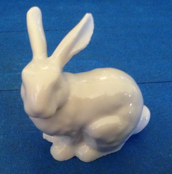
Figure 12-11. After treatment
As you can see, the after image has a nice glossy finish. Best of all, I did not have to even sand it! However, sanding will make the surface better (glossier). Furthermore, you don’t need to go so far as to use the really fine sandpaper. Just a light sanding of medium grade sandpaper is all you need.
Preparation
There is some preparation needed. You must cover the bottom and about 30cm of the sides of the basket with Kapton tape. This keeps the part from sticking to the basket, but more importantly, it keeps acetone from splashing onto the part while it is heated. Figure 12-12 shows a properly prepared basket.

Figure 12-12. Lining the basket with Kapton tape
![]() Caution Never, ever reuse the deep fryer for food preparation once you have used it for acetone. Keep it locked away in your workshop and label it appropriately to warn others.
Caution Never, ever reuse the deep fryer for food preparation once you have used it for acetone. Keep it locked away in your workshop and label it appropriately to warn others.
For best results, use some short standoffs mounted to the bottom of the basket to lift the basket away from the acetone. You can see this in the figure. Notice the bolts in the small pockets in the bottom of the basket. I used threaded brass connectors, but you can use any similar item made of metal. Just make sure that the feet and basket still fit so that the lid can be securely set on the fryer (it closes well).
Next, you need to find a place where there are no ignition sources and is well ventilated. If you attempt this indoors, you may encounter an untenable state when the acetone vapors are released. It is best to do this in an area that is either very large and has open areas (like a porch or an open garage) or, better, outside. You will need to plug the fryer in—so if you use an extension cord, be sure to use one of an appropriate size for the distance (in other words, the heavier, the better). Lastly, make sure you have a fire extinguisher ready and at least one other person in the area that is aware of what you are doing.8
The process is rather simple. We simply pour some acetone into the fryer, add our part, and turn on the heat. We don’t need a lot of heat and it won’t be for a long period—about a minute is all that is needed. You can repeat this process several times if the part doesn’t gloss like you want. The process is as follows.
- Prepare the object by doing light sanding on it to remove the larger imperfections.
- Set up the fryer in a well-ventilated area, removing the basket.
- Pour 2 to 3 ounces of acetone into the fryer.
- Place the part in the basket that has been coated with Kapton tape. If your lid has a handle in the center, the bolt point can be a source for the acetone vapor to condensate and drip. Thus, you should place the object and basket away from the center, as shown in Figure 12-13.

Figure 12-13. Placing the object in the basket
- Place the basket in the fryer and cover it with the lid.
- Plug in the fryer and turn the temperature to around 300°F or 325°F.
- Wait 60 to 90 seconds or until the boiling sounds stop. Turn off the fryer and unplug it. Never let it heat for more than 90 seconds.
 Caution Be sure to watch the process carefully. If anything goes wrong, turn off the fryer!
 - Wait 1 hour to remove the lid and allow the vapor to dissipate.
- Wait 1 more hour for the part to harden a bit and inspect the part.
- Repeat steps 2–8 until the part is completely glossed.
When satisfied with the finish, allow the part to dry overnight before removing it from the basket or handling in any way. Until the acetone evaporates, it will be soft and can be molded or blemished with fingerprints.
![]() Note Depending on the size of the object, it may take more than 1 hour for it to cure completely. Do not handle the part until it has set overnight and hardened (all of the acetone has evaporated).
Note Depending on the size of the object, it may take more than 1 hour for it to cure completely. Do not handle the part until it has set overnight and hardened (all of the acetone has evaporated).
When you add acetone, you don’t need to add very much. You need only a couple of ounces. There is no magical formula. Just cover about one-third of the bottom of the fryer.
When heating, don’t turn up the temperature more than about 325°F. This may be tempting because we start the fryer cold (at room temperature). Thus, it may take about 30 seconds to reach temperature, which is fine because it only takes about 30 to 60 seconds for the acetone to turn to vapor.
You should see the clear lid fog a bit when the temperature is reached. This is normal and nothing to be alarmed about; it isn’t smoke, it’s acetone vapor. On the other hand, if you see acetone condensing on the top, you have used too much acetone. This could be a problem if the acetone accumulates enough to drip on the part. This is why you should watch the process carefully, so that you can abort if something like that happens. To do so, cut the power and lift the lid straight up. Allow the vapors to dissipate and wipe the lid clean, and then restart the process.
The vapor bath is very corrosive to the adhesive on the Kapton tape, which can cause it to lose adhesion to the basket. I find I have to replace the Kapton tape about every three to four uses. Also, if you leave the part in the vapor too long, it has a tendency to stick to the Kapton tape and tear when you remove it.
There is no other cleanup necessary, other than taking the precaution to allow the fryer and basket to cool completely before storing. If you have any acetone remaining in the fryer, you can either pour it back into its container (only when the fryer is cool) or simply allow it to evaporate. Having some left over after 2 hours means you have used too much acetone. Try using about half an ounce less next time.
Be sure to store your fryer in a place where others cannot accidentally encounter it and attempt to use it for preparing food. In other words, don’t store it in your home! Keep it in a garage, shed, workshop, or if you have none of those, ask a neighbor or friend who does if you can store it there.
If you print an object that has multiple parts, such as a sculpture, model kit, or object that has been divided into parts to fit your build volume, you have to take a bit more care when finishing the parts. This includes making sure the parts fit together, as well as how to apply the surface treatment. This section provides some tips to help make your finishing of multipart things easier.
SPLITTING INTO PARTS TO FIT BUILD VOLUME
If you encounter a thing you want to print, but it is larger than your build volume (it won’t fit within the confines of your axes movement), you can split the thing into parts. There are several techniques for doing this and it is beyond the scope of this book to list them all. One quick way to do it is to import the object into OpenSCAD and use the difference mechanism to slice the part by masking it with a large cube, and then reorienting the segment so that it lays flat. Repeat this as many times as needed, and you have a multipart set of objects that you can print and then reassemble.
You should not apply any surface treatment (e.g., paint) to the areas that are joined. If you are gluing the parts together, the glue may not stick to the surface treatment. You should also make sure the parts fit together very well prior to applying the surface treatment. I like to test fit all parts during the sanding process so that I can remove any extra plastic as needed. This way, if I slip or make a mistake, I won’t ruin the surface treatment (I won’t scratch the nice paint job).
Also, it may be that you can assemble the parts prior to applying the surface treatment. If you have parts that are joined but you do not want the joint to show through the surface treatment, you can fill in the joint prior to painting.
If you are printing with ABS, you can dissolve some ABS in acetone, making a paste-like substance that you can apply with a hobby knife (kind of like a trowel and spackling). Once the ABS evaporates and you sand it, the part will appear as a solid piece.
If you are using PLA, you can do the same with epoxy made for plastic. It isn’t nearly as nice, and the epoxy is hard to sand and to get the same texture as the rest of the part. Thus, it may show more once the part is painted. However, you need to take care here because some epoxy can melt or weaken PLA. It is best to experiment with scrap PLA parts until you find an epoxy that works well.
Perhaps the best advice is to sand and trim the parts so that they fit together as tight as possible. The tighter the seam, the less likely you may need to cover it up.
Finally, I’d like to impart a technique for assembling metal bits and plastic parts; more specifically, how to save some time getting those nut traps, slots, and other areas cleaned up and prepped for assembly. If you make a part with a nut trap, try to make the shape the correct size. It is often OK to make it slightly smaller and use the technique here, but making it too large can be a problem—the nut may not sit properly and turn or strip the plastic.
The best way to fit nuts and bolts (the hex heads) into plastic parts prior to assembly is to heat the nut or bolt with a butane torch, and then insert the heated metal into the part. This is really great if the opening is just a tad too small, as it will make a very tight setting for the nut or bolt. I use this technique a lot and it saves me a great deal of time trimming those tiny M3 nut traps to fit.
Summary
Once you have printed several parts and have mastered your printer’s configuration and calibration, you may start to wonder if there is more that you can do with 3D printers. Indeed there is! There is a whole world of finishing options to consider—from sanding and smoothing, to applying surface treatments such as painting, to making multipart prints fit together to appear as a single piece.
This chapter has presented all of these topics in a series of tips and techniques for you to get started finishing your prints and taking them to the next level—to become something more than a few dozen layers of plastic.
The next chapter completes the journey of 3D printing by challenging you to expand your 3D printing hobby beyond your own workshop. I will discuss sharing objects with the world, as well as presenting ideas for how you can put your 3D printing hobby to practical use by solving real-world problems.
_______________________
1You won’t have to count in hexadecimals, work with memory, or any such advanced topic. You need only a step-wise mindset to solving problems. Read on.
2Including a d20. Got crit?
3It’s 2+2+36+2+2 = 40mm.
4The part in this example is thingiverse.com/thing:232984.
5Guilty as charged. Do as I say, not as I do.
6Can you guess how I know this?
7Open flames, gas heaters, energetic cats on pile carpeting, and so forth.
8Have I frightened you? Don’t be. Just be cautious.