Let’s Begin I/O
In the last chapter, we looked at the peripherals available to users of PIC® microcontrollers. One of the things we saw on the block diagram were the ports. As was described, the ports are registers that provide access to the pins of the microcontroller. The ports on the PIC16F1717 can be used for input or output and can provide access to the many peripherals onboard the microcontroller. In this chapter, we discuss input and output, also written as I/O. We use I/O to interface to LEDs, switches, and seven segment displays.
Before we look at the code to make this happen, there are some registers that you must understand, including knowing how to configure them in order to effectively use I/O on the microcontroller.
TRIS Register
The first register we examine is the TRIState (TRIS) register . The TRIS register gets its name from the fact that it can be in three states. It can be configured for output high, output low, or input. The TRIS register is used to make a port either an input or an output. To make a port an output, we write a 0 to the corresponding TRIS register of that port. To make it an input, we write a 1.
For example, to set PORTB as an output port, we do the following:
TRISB = 0;Similarly, if we wanted to make that same port an input port, we do the following:
TRISB = 1;It is important to efficiently manage the precious I/O since PIC® microcontrollers do not contain an infinite number of pins. The DIP version of the PIC16F1717 used for prototyping contains 40 pins. The reason I stated this obvious point is to reiterate the fact that I/O must be properly designated. Thus, it is sometimes necessary to assign one pin on a particular port to serve either an input or output function. For example, to set one individual bit (in this case, BIT 0 on PORTB) as an output, we do the following:
TRISBbits.TRISB0 = 0;Similarly, if we wanted to set one bit as an input, we write:
TRISBbits.TRISB1 = 1;As you can see from these assignments, Microchip makes it very easy to access individual I/O on PIC® microcontrollers and configure their associated registers. There is no need to mess with esoteric pointer functions or deal with mind-boggling bitwise logic. In fact, accessing individual pins for I/O operations on PIC® microcontrollers is easiest on a Microcontroller.
It is imperative to remember that data will not move from the port register to the pins on the microcontroller unless you give the appropriate TRIS register some value.
Now let’s look at some other important registers.
PORT Register
We have referred to the ports of the PIC® microcontrollers on several occasions. On the PIC16F1717, there are a total of five ports ranging from A to E. These ports are 8-bit wide and therefore generally these ports have from bits 0 to 7. The exception to this on the PIC16F1717 is PORTE, which is a 4-bit wide input port and 3-bit wide output port.
The port register essentially reads the voltage levels of the pins on the device.
Output Latch Registers
The Output Latch Registers (LAT) are an important and overlooked type of register related to I/O. Prior to the enhancements made by Microchip to the PIC16F family, only the 18F family contained LAT registers. The LAT registers are an improvement on the PORT registers for writing data to output. The LAT register improves on problems associated with the PORT register for writing data to the pins. Note that it is advisable to output data to ports using the LATx register and to read data using the PORTx register.
This is because, as previously stated, the LAT register improves on any problems that may occur while simply using the PORT register for outputting data. The reason you use the PORT register for reading data from the input pins is because the PORT register reads the actual voltage level on the pin, whereas a read of the LAT register simply reads the same without regard for the voltage level of the associated pin.
Analog Select Registers
The analog select registers (ANSEL) are used to enable or disable analog input functions on a particular pin. When using a particular I/O pin for output, it is not necessary to adjust the ANSEL register corresponding to that bit. However, if you want to use a particular I/O pin as an analog input pin, you must set the corresponding ANSEL register.
Weak Pull-Up
The ports on the PIC16F1717 have internal pull-up resistors. These are important as they reduce component count by eliminating the need for an external resistor. The weak pull-up can be used as seen in Listing 6-1.
Listing 6-1 Example of Weak Pull-Up
// First we must enable weak pull-ups globallyOPTION_REGbits.nWPUEN = 0;// Then we configure it for the individual pin, in this PINB0 5 WPUBbits.WPUB0 = 1;
Once this is completed, we can connect a switch to the microcontroller without the need for an external pull-up resistor.
There are also options for other registers associated with the PORT, including those for input level control, open-drain, and slew rare control.
Making an LED Blink
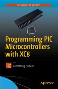
Finally, we get to the good parts! We look at making an LED blink , which is essentially the “hello world” of embedded programming. In order to do this, we first need connect the LED to the pin we intend to use. For this example, we connect the LED to PIN RD1.
Do not forget to connect a resistor to the LED or else you risk damaging it.
Let’s review the steps for creating a project in MPLAB X IDE .
Open the IDE. You will be presented with the start page.
Click the Create New icon.
Select Microchip Embedded followed by Standalone Project.
Select your device family and device.
Select your programmer. In my case, I use the ICD 3; however, you may use the PICkit™ 3 or another programmer of your choice.
Select your compiler. In this case, it’s the XC8.
Give your project a name and location.
After your project is created, right-click it and select New followed by the file of your choice.
If you forget how to create a new project, Chapter 5 provides a step-by-step guide to the process.
Now you can write some code. Based on what you have learned, you can use the following steps to set up the microcontroller for I/0. Let’s review what we must do to make this happen:
Configure the TRIS register to output on a particular port pin.
Turn off the ANSEL register associated with that particular pin.
Set the LAT register for that pin.
It would be nice to do this alone, but first there are some things we must do. As important as software is, the hardware is very important when designing with microcontrollers. Sometimes a program will compile and will not run as expected.
First, you connect the LED via a 1K resistor to PIND1, as shown in Figure 6-1.
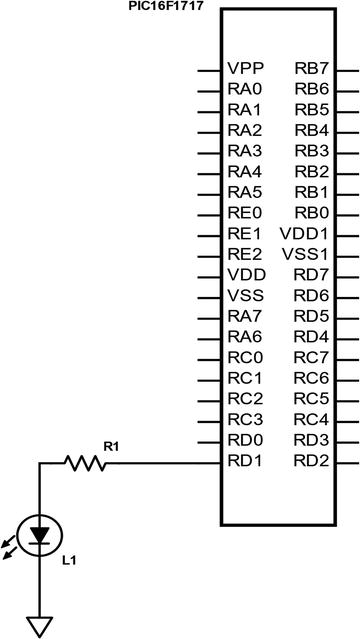
Figure 6-1 LED connected to PIC® microcontroller
Even though the hardware is connected, you simply cannot write the main program and get the code to work. You must first create a file to set the configuration bits of the microcontroller. Type the code first, then we will discuss what it does. Create a header file called 16F1717_Internal.h and enter the code shown in Listing 6-2.
Listing 6-2 PIC16F1717 Standard Header File
/** File: 16F1717_Internal.h* Author: Armstrong Subero* PIC: 16F1717 w/X OSC @ 16MHz, 5v* Program: Header file to setup PIC16F1717* Compiler: XC8 (v1.35, MPLAX X v3.10)* Program Version 2.0**Separated file into Header and C source file**Changed comments and layout** Program Description: This program header allows setup of configuration* bits and provides routines for setting up internal* oscillator and includes all devices and MCU modules** Created on January 9th, 2016, 2:50 PM******************************************************************************//********************************************************************************Includes and defines******************************************************************************/// PIC16F1717 Configuration Bit Settings// CONFIG1#pragma config FOSC = INTOSC // Oscillator Selection Bits (INTOSC oscillator:I/O function on CLKIN pin)#pragma config WDTE = OFF // Watchdog Timer Enable(WDT disabled)#pragma config PWRTE = OFF // Power-up Timer Enable(PWRT disabled)#pragma config MCLRE = OFF // MCLR Pin Function Select (MCLR/VPP pin function is MCLR)#pragma config CP = OFF // Flash Program Memory Code Protection (Programmemory code protection is disabled)#pragma config BOREN = OFF // Brown-out Reset Enable (Brown-out Reset disabled)#pragma config CLKOUTEN = OFF // Clock Out Enable (CLKOUT function is disabled. I/O or oscillator function on the CLKOUT pin)#pragma config IESO = ON // Internal/External Switchover Mode (Internal/External Switchover Mode is enabled)#pragma config FCMEN = OFF // Fail-Safe Clock Monitor Enable (Fail-Safe Clock Monitor is enabled)// CONFIG2#pragma config WRT = OFF // Flash Memory Self-Write Protection (Write protection off)#pragma config PPS1WAY = ON // Peripheral Pin Select one-way control (The PPSLOCK bit cannot be cleared once it is set by software)#pragma config ZCDDIS = ON // Zero-cross detect disable (Zero-cross detectcircuit is disabled at POR and can be enabled with ZCDSEN bit.)#pragma config PLLEN = OFF // Phase Lock Loop enable (4x PLL is enabled when software sets the SPLLEN bit)pragma config STVREN = ON // Stack Overflow/Underflow Reset Enable (StackOverflow or Underflow will cause a Reset)#pragma config BORV = LO // Brown-out Reset Voltage Selection (Brown-outReset Voltage (Vbor), low trip point selected.)#pragma config LPBOR = OFF // Low-Power Brown Out Reset (Low-Power BOR is disabled)#pragma config LVP = OFF // Low-Voltage Programming Enable (High-voltageon MCLR/VPP must be used for programming)//XC8 Standard Include#include <xc.h>#include <stdio.h>#include <stdlib.h>//Other Includes#include <stdint.h>#include <stdbool.h>#include <stddef.h>#include <math.h>//For delay routines#define _XTAL_FREQ 16000000//MCU Modules Includes//Internal oscillator setupvoid internal_32();void internal_16(); //16 MHzvoid internal_8();void internal_4();void internal_2();void internal_1();void internal_31(); //31 kHz
In this book, I use heavily commented code, thus line-by-line explanation are not included. I do, however, explain the most important aspects of the code.
This file configures the PIC® microcontroller with options such as clocks, power-up timers, brown-out resets, and watchdog timers, to name a few. These options are known as the configuration bits of the microcontroller. If the configuration bits are not set, the microcontroller will not run. You can identify the configuration bits by the prefix #pragma config. If you look below this block, you will see several standard include files. The one unique to the XC8 compiler is <xc.h> and is required for every program to be written using the XC8 compiler.
Below this section you will see a define statement: #define _XTAL_FREQ 16000000. This statement defines the speed at which the microcontroller runs, which is 16MHz. In order to ensure consistency, in this book we maintain this frequency throughout.
Moving down, you will notice some custom function declarations. These declarations allow the user to quickly and effectively change the speed of the microcontroller as needed.
Next, we look at the file that contains the body of the functions. Create another file called PIC16F1717_Internal.c and enter the code shown in Listing 6-3.
Listing 6-3 PIC16F1717 Standard Source File
/** File: 16F1717_Internal.c* Author: Armstrong Subero* PIC: 16F1717 w/Int OSC @ 16MHz, 5v* Program: Library file to configure PIC16F1717* Compiler: XC8 (v1.35, MPLAX X v3.10)* Program Version: 1.2**Added additional comments** Program Description: This Library allows you to setup a PIC16F1717** Created on January 9th, 2016, 6:45 PM*//********************************************************************************Includes and defines******************************************************************************/#include "16F1717_Internal.h"/******************************************************************************** Function: internal_32()** Returns: Nothing** Description: Sets internal oscillator to 32MHz** Usage: internal_32()******************************************************************************///Set to 32MHzvoid internal_32(){//Clock determined by FOSC in configuration bitsSCS0 = 0;SCS1 = 0;//Frequency select bitsIRCF0 = 0;IRCF1 = 1;IRCF2 = 1;IRCF3 = 1;//SET PLLx4 ONSPLLEN = 1;}/******************************************************************************** Function: internal_16()** Returns: Nothing** Description: Sets internal oscillator to 16MHz** Usage: internal_16()******************************************************************************///Set to 16MHzvoid internal_16(){//Clock determined by FOSC in configuration bitsSCS0 = 0;SCS1 = 0;//Frequency select bitsIRCF0 = 1;IRCF1 = 1;IRCF2 = 1;IRCF3 = 1;//SET PLLx4 OFFSPLLEN = 0;}/******************************************************************************** Function: internal_8()** Returns: Nothing** Description: Sets internal oscillator to 8MHz** Usage: internal_8()******************************************************************************///Set to 8MHzvoid internal_8(){//Clock determined by FOSC in configuration bitsSCS0 = 0;SCS1 = 0;//Frequency select bitsIRCF0 = 0;IRCF1 = 1;IRCF2 = 1;IRCF3 = 1;//SET PLLx4 OFFSPLLEN = 0;}/******************************************************************************** Function: internal_4()** Returns: Nothing** Description: Sets internal oscillator to 4MHz** Usage: internal_4()******************************************************************************///Set to 4MHzvoid internal_4(){//Clock determined by FOSC in configuration bitsSCS0 = 0;SCS1 = 0;//Frequency select bitsIRCF0 = 1;IRCF1 = 0;IRCF2 = 1;IRCF3 = 1;//SET PLLx4 OFFSPLLEN = 0;}/******************************************************************************** Function: internal_2()** Returns: Nothing** Description: Sets internal oscillator to 2MHz** Usage: internal_2()******************************************************************************///Set to 2MHzvoid internal_2(){//Clock determined by FOSC in configuration bitsSCS0 = 0;SCS1 = 0;//Frequency select bitsIRCF0 = 0;IRCF1 = 0;IRCF2 = 1;IRCF3 = 1;//SET PLLx4 OFFSPLLEN = 0;}/******************************************************************************** Function: internal_1()** Returns: Nothing** Description: Sets internal oscillator to 1MHz** Usage: internal_1()******************************************************************************///Set to 1MHzvoid internal_1(){//Clock determined by FOSC in configuration bitsSCS0 = 0;SCS1 = 0;//Frequency select bitsIRCF0 = 1;IRCF1 = 1;IRCF2 = 0;IRCF3 = 1;//SET PLLx4 OFFSPLLEN = 0;}/******************************************************************************** Function: internal_31()** Returns: Nothing** Description: Sets internal oscillator to 31kHz** Usage: internal_31()******************************************************************************///Set to 31kHz(LFINTOSC)void internal_31(){//Clock determined by FOSC in configuration bitsSCS0 = 0;SCS1 = 0;//Frequency select bitsIRCF0 = 0;IRCF1 = 0;IRCF2 = 0;IRCF3 = 0;//SET PLLx4 OFFSPLLEN = 0;}
This file implements the functions necessary to set the speed of the PIC® microcontroller clock.
Now comes the good part—actually making the LED light. All C programs, as you know, must contain a main function. Traditionally, the file containing this function is called main as well. Thus, create a new file called main.c and input the code, as shown in Listing 6-4.
Listing 6-4 PIC16F1717 Output Source File
/** File: Main.c* Author: Armstrong Subero* PIC: 16F1717 w/Int OSC @ 16MHz, 5v* Program: 00_Output* Compiler: XC8 (v1.38, MPLAX X v3.40)* Program Version: 1.0*** Program Description: This Program Allows PIC16F1717 to Turn on an LED** Hardware Description: An LED is connected via a 10k resistor to PIN D1** Created November 4th, 2016, 1:00 PM*//********************************************************************************Includes and defines******************************************************************************/#include "16F1717_Internal.h"/******************************************************************************** Function: void initMain()** Returns: Nothing** Description: Contains initializations for main** Usage: initMain()******************************************************************************/void initMain(){// Run at 16 MHzinternal_16();// Set PIN D1 as outputTRISDbits.TRISD1 = 0;}/******************************************************************************** Function: Main** Returns: Nothing** Description: Program entry point******************************************************************************/void main(void) {initMain();while(1){// Set PIND1 HighLATDbits.LATD1 = 1;}return;}
Compile the program and run it. The LED should light up! If the LED does not light up, ensure that you tested your connections properly. A lot of problems can be solved by simply ensuring everything is wired correctly.
Great, the LED lights up. However, we want the LED to blink. To do this, you must use the built-in delay macro in XC8. There are options to delay for clock cycles, milliseconds, or microseconds. To make the LED blink, we will use the millisecond option. This code is shown in Listing 6-5.
Listing 6-5 PIC16F1717 Flash Source File
/** File: Main.c* Author: Armstrong Subero* PIC: 16F1717 w/Int OSC @ 16MHz, 5v* Program: 01_Flash* Compiler: XC8 (v1.38, MPLAX X v3.40)* Program Version: 1.0*9 ** Program Description: This Program Allows PIC16F1717 to blink an LED at* 50% duty cycle** Hardware Description: An LED is connected via a 10k resistor to PIN D1** Created November 4th, 2016, 1:08 PM*//********************************************************************************Includes and defines******************************************************************************/#include "16F1717_Internal.h"/******************************************************************************** Function: void initMain()** Returns: Nothing** Description: Contains initializations for main** Usage: initMain()******************************************************************************/void initMain(){// Run at 16 MHzinternal_16();// Set PIN D1 as outputTRISDbits.TRISD1 = 0;}/******************************************************************************** Function: Main** Returns: Nothing** Description: Program entry point******************************************************************************/void main(void) {initMain();while(1){// Toggle LEDLATDbits.LATD1 = ~LATDbits.LATD1;// delay 500 ms__delay_ms(500);}return;}
The __delay_ms macro allows you to delay a particular period of time. We use the bitwise NOT operator to toggle the LED.
Using a Pushbutton
Now that we examined the output, let’s look at the input. As mentioned earlier, the TRIS register must be set to allow the I/O pin to act as an input. We also use the internal pull-up to avoid the use of an external resistor.
As we did with output, there is also a process to make the pin an input pin. Here are the steps for configuring a pin as an input using the internal weak pull-up resistors on the chip:
Configure the TRIS register for that pin as an input.
Turn off the ANSEL for that particular pin.
Enable weak pull-ups globally.
Enable the weak pull-ups for that particular pin.
The schematic in Figure 6-2 shows how we connect the switch and LED. The LED remains connected to RD1 and we now connect the switch to RB0.
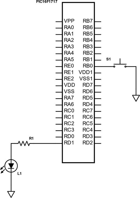
Figure 6-2 LED with pushbutton connected to a PIC® microcontroller
Listing 6-6 shows the main code. The header files and configuration bits are the same as in the last example.
Listing 6-6 PIC16F1717 Pushbutton with Internal Weak Pull-Up
/** File: Main. c* Author: Armstrong Subero* PIC: 16F1717 w/Int OSC @ 16MHz, 5v* Program: 02_Internal_Pullups* Compiler: XC8 (v1.38, MPLAX X v3.40)* Program Version: 1.0*** Program Description: This Program Allows PIC16F1717 to turn on an LED based* on a Pushbutton** Hardware Description: An LED is connected via a 1k resistor to PIN D1 and a* switch is connected to PIN B0** Created November 4th, 2016, 1:08 PM*//********************************************************************************Includes and defines******************************************************************************/#include "16F1717_Internal.h"/******************************************************************************** Function: void initMain()** Returns: Nothing** Description: Contains initializations for main** Usage: initMain()******************************************************************************/void initMain(){// Run at 16 MHzinternal_16();// Set PIN D1 as outputTRISDbits.TRISD1 = 0;// Turn off LEDLATDbits.LATD1 = 0;// Set PIN B0 as inputTRISBbits.TRISB0 = 1;// Configure ANSELB0ANSELBbits.ANSB0 = 0;// Enable weak-pullups globalOPTION_REGbits.nWPUEN = 0;// Enable weak-pullup on PINB0WPUBbits.WPUB0 = 1;}/******************************************************************************** Function: Main** Returns: Nothing** Description: Program entry point******************************************************************************/void main(void) {initMain();while(1){// Toggle LED on pushbuttonLATDbits.LATD1 = ~PORTBbits.RB0;}return;}
There may be times when it is necessary to debounce your switch. Debouncing is when you allow the microcontroller to only recognize the switch as being pressed once even when it’s pressed multiple times. Some very poor-quality switches can make multiple contacts on one button push. This in turn causes the microcontroller to register several occurrences of the switch being pushed.
There are several options for debouncing, including hardware and software methods. However, I have found that in practice, high-quality mechanical pushbuttons being used for prototyping applications do not necessarily need debouncing, especially for applications as trivial as ours. However, if you are designing a commercial product, it is highly recommended that you add debouncing to your switches. Should you need to debounce your switch, you can do so using the software and the simple method shown in Listing 6-7. Simply replace the code after the // Toggle LED on pushbutton comment in Listing 6-6 with this code.
Listing 6-7 Button Debounce Snippet
// Check if switch pressedif (RB0 == 0){// short delay__delay_ms(100);// if switch still pressedif (RB0 == 0){// turn led onLATDbits.LATD1 = 1;}}else{// keep LED offLATDbits.LATD1 = 0;}
We use the method of inputting a short delay after the initial button press is detected, then we recheck the switch before any further action is performed. If the switch is still closed, we turn on the LED. Note also that the actual delay time before the recheck may vary according to the switch. Hence, you should test the delay time to ensure that it is compatible with your particular pushbutton.
There may also be a time when you don’t want to use the internal weak pull-up. In this case, you can omit all parts of the code related to setting up the weak pull-up resistors. Here is how you do that. You add a pull-up resistor externally, which is connected as shown in the schematic in Figure 6-3.
Figure 6-3 Connecting the switch with external pull-up
The only thing that changes in the hardware configuration is the addition of a pull-up resistor. The standard value of the pull-up resistor is 10k.
As for the software, we will remove the parts of the code that set up the internal pull-ups for use (see Listing 6-8).
Listing 6-8 PIC16F1717 Pushbutton Without Internal Pull-Up
/** File: Main.c* Author: Armstrong Subero* PIC: 16F1717 w/Int OSC @ 16MHz, 5v* Program: 03_Pushbutton* Compiler: XC8 (v1.38, MPLAX X v3.40)* Program Version: 1.0*** Program Description: This Program Allows PIC16F1717 to turn on an LED* based on a Pushbutton** Hardware Description: An LED is connected via a 10k resistor to PIN D1 and a* switch is connected to PIN B0** Created November 4th, 2016, 1:08 PM*//********************************************************************************Includes and defines******************************************************************************/#include "16F1717_Internal.h"/******************************************************************************** Function: void initMain()** Returns: Nothing** Description: Contains initializations for main** Usage: initMain()******************************************************************************/void initMain(){// Run at 16 MHzinternal_16();// Set PIN D1 as outputTRISDbits.TRISD1 = 0;// Turn off LEDLATDbits.LATD1 = 0;// Set PIN B0 as inputTRISBbits.TRISB0 = 1;// Configure ANSELB0ANSELBbits.ANSB0 = 0;}/******************************************************************************** Function: Main** Returns: Nothing** Description: Program entry point******************************************************************************/void main(void) {initMain();while(1){// Toggle LED on PUSH ButtonLATDbits.LATD1 = ~PORTBbits.RB0;}return;}
Seven Segment Displays
LCDs and OLED displays are undoubtedly the most popular choices for relaying output to users of embedded systems. Adding a display will add cost to your system. There will be times when you’ll want to give the users output and mere LED output won’t suffice. In such cases, you can use a seven segment display to give the users a little more information.
Seven segment displays are basically packages that traditionally contain seven LEDs. If you count the decimal point segment available on most seven segment displays, it is eight in reality. Each one of the LEDs in this package is referred to as a segment. Hence the name seven segment display; see Figure 6-4.
These LEDs can output hexadecimal digits in the form of the digits 0-F. These displays also come in two varieties, which can either be common anode or common cathode. In this book, we use the common cathode variety. Figure 6-4 shows how the digits of a common-cathode seven segment LED are arranged.
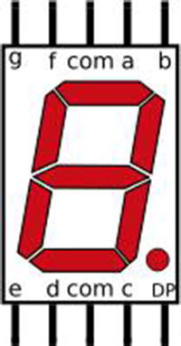
Figure 6-4 A seven segment display pinout
As you see, each pin is associated with a letter A-G, and there is also a pin for the decimal point marked as DP. There are two pins marked COM. This is short for “common” and will connect to the ground.
To display numbers on the display, the segments associated with that pin are turned on. For example, in order to display the number 8, all of the segments on the LED would be on. These pins would then be connected to a particular port on the microcontroller. The numbers would then be sent to the microcontroller port that the seven segment display is connected to.
Since the seven segment display is, after all, a group of LEDs in one package, you need to connect resistors to each segment of the displays to ensure that you do not damage them.
Note that if you are using the common anode variety, the hexadecimal numbers sent to the port will be slightly different. This is because in the common anode variety, all the LEDs are connected to power instead of ground.
Now that you have a fair idea about how these displays operate, let’s look at the schematic for connecting the seven segment display to the microcontroller (see Figure 6-5). The pins are connected to PORTD, with A being connected to RD0, B being connected to RD1, and so forth, until all the pins are connected with the exception of the decimal point pin. The common is connected to ground .
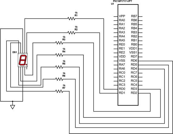
Figure 6-5 PIC16F1717 with seven segment connected
Now we write the code required for using a seven segment display, as shown in Listing 6-9.
Listing 6-9 PIC16F1717 Seven Segment Display
/** File: Main.c* Author: Armstrong Subero* PIC: 16F1717 w/Int OSC @ 16MHz, 5v* Program: I01_Seven_Segment* Compiler: XC8 (v1.38, MPLAX X v3.40)* Program Version: 1.0** Program Description: This Program Allows PIC16F1717 to drive a single* seven segment display, it displays the hexadecimal* digits 0-F on the seven segment display.** Hardware Description: An seven segment display of the cathode variety is* connected to port D of the microcontroller via 1k* resistors.** Created February 16th, 2017, 6:31 PM*//********************************************************************************Includes and defines******************************************************************************/#include "16F1717_Internal.h"unsigned char Display(unsigned char digit);/******************************************************************************** Function: void initMain()** Returns: Nothing** Description: Contains initializations for main** Usage: initMain()******************************************************************************/void initMain(){// Run at 16 MHzinternal_16();// Set PORTD as outputTRISD = 0;ANSELD = 0;}/******************************************************************************** Function: Main** Returns: Nothing** Description: Program entry point******************************************************************************/void main(void) {// loop variableint i;initMain();// Keep displaying digits 0-F// and update it every secondwhile(1){for (i = 0; i <= 15; i++){// Now the hex values for the array are derived based on the type of seven// segment display. In our case we use the common cathode version.// For example to display the number '7', this means that we must have segments// a,b and c enabled. This would be "0000111" in binary with a '1' signifying// the particular segment. This would equate to 0x07 in hex. So when//'0x07' is written to the PORTD.// based on the iteration of the array by the for loop, we display each letter// to PORTD.LATD = Display(i);__delay_ms(1000);}}return;}/******************************************************************************** Function: unsigned char Display(unsigned char digit)** Returns: unsigned char numbers** Description: Function that takes a number and returns its index in an array* corresponding to the hexadecimal digit******************************************************************************/unsigned char Display(unsigned char digit){// variable representing numbersunsigned char numbers;// an array of the digits 0-Funsigned char DIGITS[] = {0x3F, 0x06, 0x5B, 0x4F, 0x66, 0x6D, 0x7D, 0x07,0x7F, 0x6F, 0x77, 0x7C, 0x39, 0x5E, 0x79, 0x71};// assign index given by user to variablenumbers = DIGITS[digit];// return itreturn numbers;}
Seven Segment Display Multiplexing
There are times when you’ll want to want to use more than one seven segment display in your application. One seven segment display typically uses a full port of your microcontroller (see Figure 6-6). Driving two seven segment displays would use about 16 pins of your microcontroller! This is almost half of the pins on the PIC16F1717. To avoid this, you can either use a higher pin count microcontroller, which costs more and adds to the total cost of your system, or you can use multiplexing.
Display multiplexing is the process of using displays in such a way that the entire display is not on at the same time. What this means for seven segment displays is that only one digit is on at a time. However, the microcontroller switches between updating these two displays so quickly that users cannot detect it. In order to multiplex these displays, we use transistors to turn the displays on and off.
The major advantage of multiplexing is that it uses less I/O on the microcontroller. Let’s look at how we can multiplex seven segment displays on the PIC16F1717 (see Listing 6-10).
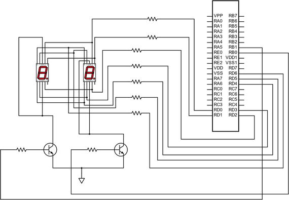
Figure 6-6 PIC16F1717 multiplexed seven segment display
Listing 6-10 PIC16F1717 Dual Seven Segment Display
/** File: Main.c* Author: Armstrong Subero* PIC: 16F1717 w/Int OSC @ 16MHz, 5v* Program: I02_Seven_Segment_Mul* Compiler: XC8 (v1.38, MPLAX X v3.40)* Program Version: 1.0** Program Description: This Program Allows PIC16F1717 to drive dual* multiplexed seven segment displays, it displays the* numbers from 0 to 99 on the displays depending on* which of two pushbuttons is pressed.** Hardware Description: Dual seven segment displays of the cathode variety is* connected to port D of the microcontroller via 1k* resistors. There are two transistors connected in* common emitter configuration on pins RB0 and RB1* respectively. There are also two pushbuttons connected* to pins RC4 and RC5.** Created February 16th, 2017, 9:55 PM*//********************************************************************************Includes and defines******************************************************************************/#include "16F1717_Internal.h"unsigned char Display(unsigned char digit);// digit one enable#define DIGITONE LATB0// digit two enable#define DIGITTWO LATB1/******************************************************************************** Function: void initMain()** Returns: Nothing** Description: Contains initializations for main** Usage: initMain()******************************************************************************/void initMain(){// Run at 16 MHzinternal_16();// Set PORTD as output// Analog disabledTRISD = 0;ANSELD = 0;// Set PORTB as output// Analog disabledTRISB = 0;ANSELB = 0;// Set RC4 and RC5 as inputTRISCbits.TRISC4 = 1;TRISCbits.TRISC5 = 1;// Turn of analog on CANSELC = 0;// Enable weak-pullups globalOPTION_REGbits.nWPUEN = 0;// Enable weak-pullup on RC4 and RC5WPUCbits.WPUC4 = 1;WPUCbits.WPUC5 = 1;}/******************************************************************************** Function: Main** Returns: Nothing** Description: Program entry point******************************************************************************/void main(void) {// count variableint count = 0;// most significant digitint MSD;// least significant digitint LSD;initMain();// Keep displaying digits 0-F// and update it ever secondwhile(1){// If RC4 pressed increment countif(RC4 == 0){__delay_ms(100);if (RC4 == 0){count++;}}// IF RC5 pressed decrement countif (RC5 == 0){__delay_ms(100);if(RC5 == 0){count--;}}// Get MSD and LSDMSD = count/10;LSD = count%10;// Display MSDLATD = Display(MSD);DIGITTWO = 1;__delay_ms(20);DIGITTWO = 0;// Display LSDLATD = Display(LSD);DIGITONE = 1;__delay_ms(20);DIGITONE = 0;// If value invalid set to 0if (count > 99 || count < 0){count = 0;}__delay_ms(1);}return;}/******************************************************************************** Function: unsigned char Display(unsigned char digit)** Returns: unsigned char numbers** Description: Function that takes a number and returns its index in an array* corresponding to the hexadecimal digit******************************************************************************/unsigned char Display(unsigned char digit){// variable representing numbersunsigned char numbers;// an array of the digits 0-Funsigned char DIGITS[] = {0x3F, 0x06, 0x5B, 0x4F, 0x66, 0x6D, 0x7D, 0x07,0x7F, 0x6F, 0x77, 0x7C, 0x39, 0x5E, 0x79, 0x71};// assign index given by user to variablenumbers = DIGITS[digit];// return itreturn numbers;}
This program displays the Most Significant Digit (MSD) by dividing the current count by 10. The Least Significant Digit (LSD) is found by finding the modulo of the count and 10. Two pushbuttons are used to increment and decrement the count. If the user tries to enter a count of more than 99 or less than 0, the counter resets to 0. The program runs in a 1ms loop and slight jitter can be seen on the seven segment displays.
Project: Countdown Timer
Although we haven’t covered much, we can still build a useful project. We will use the knowledge we have gained so far to make a basic countdown timer. The idea is to build a timer that can count down from a value of up to 99 seconds based on what is set by the user. We will use one button for incrementing the time, one for decrementing time, and another button to begin the countdown. The schematic for this circuit is shown in Figure 6-7 and the code is shown in Listing 6-11.
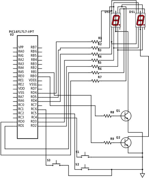
Figure 6-7 PIC16F1717 countdown timer project schematic
Listing 6-11 PIC16F1717 Countdown Timer Project Code
/** File: Main.c* Author: Armstrong Subero* PIC: 16F1717 w/Int OSC @ 16MHz, 5v* Program: P01_Countdown_Timer* Compiler: XC8 (v1.38, MPLAX X v3.40)* Program Version: 1.0** Program Description: This Program Allows PIC16F1717 to countdown from a* time of up to 99 seconds which is determined by the* user.** Hardware Description: Dual seven segment displays of the cathode variety is* connected to port D of the microcontroller via 1k* resistors. There are two transistors connected in* common emitter configuration on pins RB0 and RB1* respectively. There are also two pushbuttons connected* to pins RC4 and RC5 used for decrementing and* incrementing. There is also a button connected to* RC6 used to begin the countdown.** Created February 16th, 2017, 11:16 PM*//********************************************************************************Includes and defines******************************************************************************/#include "16F1717_Internal.h"unsigned char display(unsigned char digit);void countDown(unsigned char number);void showNumber(unsigned char number);// display port#define DISPLAYPORT LATD// digit one enable#define DIGITONE LATB0// digit two enable#define DIGITTWO LATB1/******************************************************************************** Function: void initMain()** Returns: Nothing** Description: Contains initializations for main** Usage: initMain()******************************************************************************/void initMain(){// Run at 16 MHzinternal_16();// Set PORTD as output// Analog disabledTRISD = 0;ANSELD = 0;// Set PORTB as output// Analog disabledTRISB = 0;ANSELB = 0;// Set RC4, RC5 and RC6 as inputTRISCbits.TRISC4 = 1;TRISCbits.TRISC5 = 1;TRISCbits.TRISC6 = 1;// Turn of analog on CANSELC = 0;// Enable weak-pullups globalOPTION_REGbits.nWPUEN = 0;// Enable weak-pullup on RC4, RC5 and RC6WPUCbits.WPUC4 = 1;WPUCbits.WPUC5 = 1;WPUCbits.WPUC6 = 1;}/******************************************************************************** Function: Main** Returns: Nothing** Description: Program entry point******************************************************************************/void main(void) {// count variableunsigned char count = 0;initMain();while(1){// If RC4 pressed increment countif(RC4 == 0){__delay_ms(100);if (RC4 == 0){count++;}}// If RC5 pressed decrement countif (RC5 == 0){__delay_ms(100);if(RC5 == 0){count--;}}// If RC6 pressed begin countdownif (RC6 == 0){__delay_ms(100);if (RC6 == 0){countDown(count);}}// If value invalid set to 0if (count > 99 || count < 0){count = 0;}// show number on displayshowNumber(count);__delay_ms(1);}return;}/******************************************************************************** Function: unsigned char Display(unsigned char digit)** Returns: unsigned char numbers** Description: Function that takes a number and returns its index in an array* corresponding to the hexadecimal digit******************************************************************************/unsigned char display(unsigned char digit){// variable representing numbersunsigned char numbers;// an array of the digits 0-Funsigned char DIGITS[] = {0x3F, 0x06, 0x5B, 0x4F, 0x66, 0x6D, 0x7D, 0x07,0x7F, 0x6F, 0x77, 0x7C, 0x39, 0x5E, 0x79, 0x71};// assign index given by user to variablenumbers = DIGITS[digit];// return itreturn numbers;}/******************************************************************************** Function: void countdown(unsigned char number)** Returns: nothing** Description: Begins a countdown based on number passed to function******************************************************************************/void countDown(unsigned char number){// loop counterint i;// begin countdownfor (i = number; i >= 0; i--){showNumber(i);__delay_ms(1000);}return;}/******************************************************************************** Function: void shownumber(unsigned char number)** Returns: nothing** Description: Displays a number on the port specified******************************************************************************/void showNumber(unsigned char number){// most significant digitunsigned char MSD;// least significant digitunsigned char LSD;// Get MSD and LSDMSD = number/10;LSD = number%10;// Display MSDDISPLAYPORT = display(MSD);DIGITTWO = 1;__delay_ms(20);DIGITTWO = 0;// Display LSDDISPLAYPORT = display(LSD);DIGITONE = 1;__delay_ms(20);DIGITONE = 0;}
If we had covered interrupts and timers, this project would have been much more efficient and effective. Currently during the countdown, the displays flash every second. This is because, since we are using the delay function, for one second the microcontroller doesn’t do anything. When you learn about timers in Chapter 8, you can revisit this project and use one of the onboard timer modules if you want.
Peripheral Pin Select
Though we will not use it in this chapter, let’s take a quick look at the Peripheral Pin Select (PPS) module . On older PIC® microcontrollers, the I/O ports had fixed functions with regard to which peripherals were accessed by which pins. On newer PIC® microcontrollers, PPS was introduced to avoid this problem.
As you can see in Figure 6-8, the pins on the PIC16F1717 do not have a fixed peripheral input and output. This provides enormous possibilities with regard to board layout and circuit design. Previously to having PPS, designers had to design their circuit around the chip. While this may still be true today, the requirement is not as critical, as it is easier to adjust which pins on the chip you place your peripheral output or input. This also makes it possible to reconfigure which pins are accessed by the microcontroller at runtime and also allows an easier path to migration of legacy designs to newer ones. PPS is a very powerful feature.
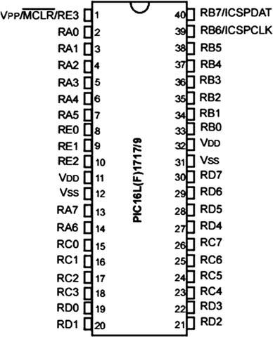
Figure 6-8 PIC16F1717 pinout
Conclusion
This chapter looked at how to use input and output on a PIC® microcontroller while looking at its applications of driving LEDs, switches, and seven segment displays. We covered display multiplexing and you saw how to build a simple project using what you have learned so far.