Sound is a great way to communicate information to the user of a device. You can use sound to provide feedback for user actions like tapping a button, to alert the user when a background task such as a timer or a download has finished, and much more.
Both the ESP32 and the ESP8266 support audio playback. Some development boards, including the M5Stack FIRE, come with a speaker built in. If your board doesn’t include a speaker, you can attach one yourself. In this chapter, you’ll learn how to play sounds using an inexpensive speaker that’s easy to attach directly to an ESP32 or ESP8266. You’ll also learn how you can achieve higher-quality audio playback using an external I2S audio driver, and how to choose the optimal audio format, balancing quality and storage space, for your project.
Speaker Options
If you’re not using a development board with a built-in speaker, you’ll need to wire a speaker to your device before running the examples.

Mini metal speaker from Adafruit
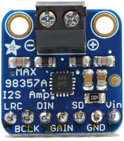
I2S chip from Adafruit

Mono enclosed speaker from Adafruit
An I2S chip adds additional cost, but it may be necessary if your product needs high-quality sound. In addition, using an I2S chip has lower CPU overhead on the ESP8266, which may also make it worth the cost. You can decide which option works best for you.
If you simply want to try out the audio playback capabilities of the Moddable SDK, the fastest way to start is with the analog speaker. If you later decide you want higher-quality audio, you can always switch to using the I2S chip and mono enclosed speaker. The JavaScript APIs to play audio are identical regardless of which setup you choose, so you will not have to change your application code. You do, however, have to configure audio settings differently for each option. The hosts for this chapter take care of the audio configuration in their manifest.json files. They assume you’re using the speaker shown in Figure 7-1 or the I2S chip and speaker shown in Figures 7-2 and 7-3.
Adding the Analog Speaker
This section explains how to connect the analog speaker to your ESP32 or ESP8266.
ESP32 Wiring Instructions
Wiring to connect the speaker to ESP32
Speaker | ESP32 |
|---|---|
Wire 1 | GPIO25 (D25) |
Wire 2 | GND |
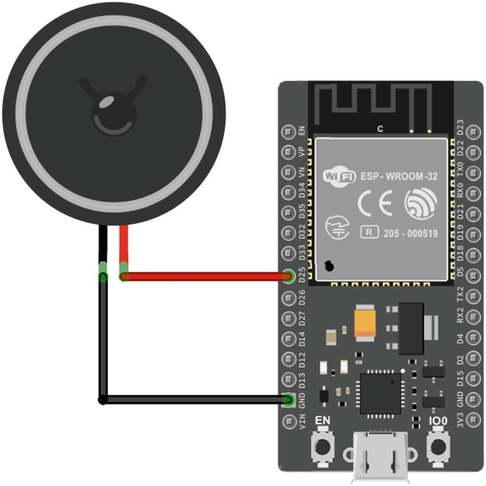
Wiring diagram for connecting the speaker to ESP32
ESP8266 Wiring Instructions
Wiring to connect the speaker to ESP8266
Speaker | ESP8266 |
|---|---|
Wire 1 | GPIO3 (RX) |
Wire 2 | GND |
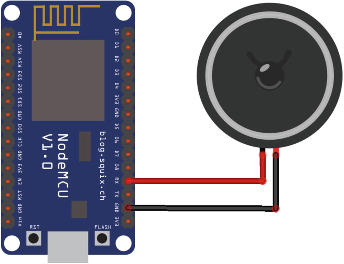
Wiring diagram for connecting the speaker to ESP8266
- 1.
Disconnect the speaker from GPIO3.
- 2.
Install an example as usual.
- 3.
Reconnect the speaker to GPIO3.
- 4.
Reset the ESP8266 to run the example.
If you’re using Moddable One, GPIO3 is on the small connector where you attach the programming adaptor. After installing an audio example, disconnect the programming adaptor, connect the speaker, and use a USB cable to power Moddable One.
It doesn’t matter which wire of the speaker goes to GPIO3 and which wire goes to GND on the ESP8266.
Adding an I2S Chip and Digital Speaker
This section explains how to attach the I2S chip to your ESP32 or ESP8266 and the digital speaker to the I2S chip.
ESP32 Wiring Instructions
Wiring to connect the I2S chip to ESP32
I2S Chip | ESP32 |
|---|---|
LRC | GPIO12 (D12) |
BCLK | GPIO13 (D13) |
DIN | GPIO14 (D14) |
GND | GND |
Vin | 3V3 |
Wiring to connect the speaker to the I2S chip
Speaker | I2S Chip |
|---|---|
Black wire | – |
Red wire | + |

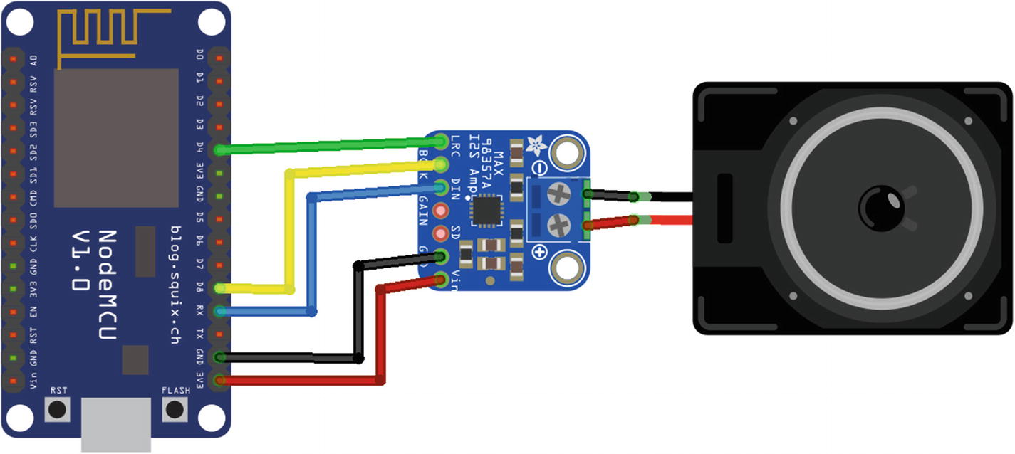
Wiring diagram for speaker, I2S chip, and ESP32
ESP8266 Wiring Instructions
Wiring to connect the I2S chip to ESP8266
I2S Chip | ESP8266 |
|---|---|
LRC | GPIO2 (D4) |
BCLK | GPIO15 (D8) |
DIN | GPIO3 (RX) |
GND | GND |
Vin | 3V3 |
Wiring to connect the speaker to the I2S chip
Speaker | I2S Chip |
|---|---|
Black wire | – |
Red wire | + |
Wiring diagram for speaker, I2S chip, and ESP8266
Installing the Audio Host
The examples in this chapter are installed using the pattern described in Chapter 1: you install the host on your device using mcconfig, then install example applications using mcrun.
There are two host apps available in the $EXAMPLES/ch7-audio/host-pdm and $EXAMPLES/ch7-audio/host-i2s directories. The difference between the two is how they configure audio settings. Use host-i2s if you’re using the I2S chip and speaker combination and host-pdm if you’re using just the speaker. Navigate to the directory from the command line and install it with mcconfig.
The AudioOut Class
The AudioOut class supports playback of uncompressed mono or stereo audio at 8 or 16 bits per sample and playback of mono audio compressed using the IMA ADPCM algorithm. The built-in mixer can combine up to four channels of audio for simultaneous playback. It can generate callbacks at specified points during audio playback—for example, to synchronize onscreen drawing with audio playback. AudioOut generates output in either 8-bit or 16-bit audio and sends it to a pseudo-analog output or a digital I2S digital-to-analog convertor.
With so many features, working with audio requires understanding the tradeoffs of the options available to help you make a decision about the best way to play audio in your product.
AudioOut Configuration
This section describes the audio hardware protocols, data formats, and other configuration options for the AudioOut class. For the examples in this chapter, the settings are configured in the manifest of the host.
Audio Hardware Protocols
The AudioOut class supports two different hardware protocols, PDM and I2S, as described in this section.
Pulse-Density Modulation (PDM)
Pulse-density modulation , or PDM, is a variation of PWM that rapidly toggles a digital output pin to create energy levels that correspond to the desired output signal. This way of playing audio is sometimes called an analog audio output because the PDM conversion synthesizes a signal that, when averaged over time, matches the energy levels output by an analog signal.
The advantage of PDM is that it works with only the built-in digital output hardware of your microcontroller. One disadvantage of PDM is that the audio is of lower quality; for this reason, PDM audio is primarily useful for sound effects in a user interface or game, not for music or spoken word.
The ESP32 has built-in hardware to convert audio data to PDM, so there’s no CPU overhead when using this protocol. The ESP8266, however, has no PDM conversion hardware; the conversion occurs in software, thereby using some CPU cycles.
Listing 7-1.
When set to 1, the DAC property tells the AudioOut implementation to use PDM output. No output pin is specified because only digital pin 25 on the ESP32 supports PDM output.
Listing 7-2.
The pdm property with a nonzero value indicates to use PDM output. The value must be 32, 64, or 128. The value 32 specifies that no oversampling should be performed in the conversion; this requires less time and memory but results in lower-quality output. The greater values provide better quality.
I2S
The other hardware protocol supported by the AudioOut class is I2S, a protocol designed to connect digital audio devices. I2S transmits unmodified audio samples over a digital connection from the microcontroller to a dedicated audio output component that performs the digital-to-analog conversion using specialized algorithms and hardware to generate a high-quality result. Both the ESP32 and the ESP8266 have built-in hardware support for transmitting audio data using I2S , so there’s very little CPU overhead on the microcontroller for playing audio.
Using I2S requires an external component, which is an additional cost, and uses at least two, and often three, digital pins, whereas PDM output uses just a single digital pin. On the other hand, I2S audio hardware generates a very high-quality audio output, so the limiting factor for quality becomes the speaker used for output, not the way digital samples are converted to an analog signal.
I2S parts vary widely. Some have no configuration options, while others include an I2C connection to configure the part and do not operate correctly until they’ve been configured. This section assumes you’re using an I2S part that either requires no configuration or has already been configured.
Listing 7-3.
The bck_pin, lr_pin, and dataout_pin properties correspond to the three pins of the I2S hardware protocol. The default values are 26, 25, and 22, respectively. The bitsPerSample property indicates the size of the sample in bits to transmit over the I2S connection. For many I2S components, this is 16, the default value, but for others 32 bits is required.
Listing 7-4.
The ESP8266 implementation supports 16-bit sample output only, so there’s no bitsPerSample property.
Audio Data Formats
The audio data your application plays must be stored in a format compatible with the AudioOut class and the audio output hardware connected to the microcontroller. For maximum efficiency and simplicity, AudioOut uses a custom data format to store digital audio; this format is called MAUD, short for Moddable Audio. It consists of a simple header followed by the audio samples. The tools you use to build your application know how to convert standard WAVE audio files (files with a .wav file extension) containing uncompressed audio into MAUD resources, eliminating the need for you to create MAUD files yourself. The conversion tool is called wav2maud and is automatically invoked by mcconfig and mcrun. If your audio is stored in another format—for example, MP3—you must first convert it to a WAVE file; the free Audacity application is a good tool for this task.
Listing 7-5.
The bitsPerSample property may be either 8 or 16, although 16 is more common. Similarly, the numChannels property may be 1 (mono) or 2 (stereo); however, it’s rare to play stereo sounds for user interface interactions on a microcontroller, so the value is usually 1.
Listing 7-6.
When mcconfig and mcrun process the manifest, they invoke wav2maud to convert the file bflatmajor.wav to a resource in the MAUD format. The audio is converted so that the bits per sample, number of channels, and sample rate of the audio in the MAUD resource match those defined in the audioOut section of the manifest. Based on the preceding example, the audio samples are 16-bit mono at 11,025 Hz sample rate.
Audio Compression
Audio data can take up a great deal of storage space. Ten seconds of 16-bit mono audio at 8 KHz uses 160,000 bytes of storage, or about 15% of the 1 MB flash address space of an ESP8266, and is still only about the quality of an analog telephone call. Audio compression is commonly used to reduce the size of audio stored on digital devices and transmitted over the internet. The algorithms used there, including MP3, AAC, and Ogg, just barely run on most microcontrollers, so they aren’t practical here. A simpler audio compression format, IMA ADPCM (adaptive differential pulse-code modulation), provides 4:1 compression of 16-bit audio samples and is significantly less complex than MP3, AAC, or Ogg, making it suitable for real-time use on the ESP32 and ESP8266.
Your audio is automatically compressed during the build. The 10 seconds of 16-bit mono 8 KHz audio mentioned previously shrinks from 160,000 to 40,000 bytes. There’s some reduction in quality, but for many purposes—for example, user interface sound effects—the difference may be unnoticeable.
Setting the Audio Queue Length
Each queue entry uses some memory (24 bytes as of this writing), so you should not allocate more than you need. If your project makes simple use of audio, you can reduce the default to recover that memory.
Playing Audio with AudioOut
The AudioOut class provides a variety of different audio playback capabilities to help you incorporate audio feedback into your project’s user experience. The playback engine is able to seamlessly play back sequences of samples. It provides a callback mechanism to synchronize audio with other parts of the user experience. It even supports real-time mixing together of multiple channels of audio, a capability that’s quite unusual on microcontrollers. This section introduces these capabilities and many others.
Instantiating AudioOut
The number of streams indicates the number of sounds that may be played simultaneously, up to a maximum of four. Since each stream uses some additional memory, it’s best to configure the AudioOut instance for only as many as needed. The basic sound example plays a single sound, so it needs only one stream.
The sample rate, number of bits per sample, and number of channels are defined in the manifest, so they’re not passed as properties in the dictionary to configure the AudioOut instance. The audio resources are stored in that same format, because mcconfig, mcrun, and wav2maud perform any needed format conversion.
Playing a Single Sound
Repeating a Sound
Using Callbacks to Synchronize Audio
Listing 7-7.
Using Commands to Change Volume
Listing 7-8.
Playing a Sequence of Sounds
Listing 7-9.
A callback is enqueued after the samples; once all the samples have played, the callback is invoked and enqueues the samples again, causing the sequence to play repeatedly.
Playing Sounds Simultaneously
Playing Part of a Sound
Flushing the Audio Queue
One situation where this is useful is when you have one channel playing a background sound effect on infinite repeat using channel 0 while using channel 1 for interactive audio sound effects. You can stop the background sound effects by flushing channel 0, which allows channel 1 to continue playing without interruption. This is in contrast to calling stop on the AudioOut instance, which immediately ends playback on all channels.
Conclusion
In Chapter 5, you learned how to interface with sensors and actuators. Now you can trigger sound effects in response to sensor readings or to indicate when an actuator is performing an action.
In the next few chapters, you’ll learn how to work with a touch screen. You can provide audio feedback for user actions onscreen or add alert sounds to draw the user’s attention back to the display. Pairing audio feedback and visual feedback delivers a more complete user experience.