
Sensors and actuators are integral parts of nearly every IoT product. Sensors gather data from the environment, such as the temperature, humidity, and light levels, and translate it into electrical signals that a microcontroller or other system can react to. Actuators do the opposite: they take electrical signals and translate them into physical actions, such as turning a motor or a light on or playing a sound.
Just as there are different networking protocols that define how data is shared over the network, there are different hardware protocols that define how sensors and actuators communicate with the microcontroller they’re connected to. The Moddable SDK includes JavaScript APIs for a variety of hardware protocols, including digital, analog, PWM, servo, and I2C. These APIs enable you to interact with off-the-shelf hardware or your own circuits from your ESP32 or ESP8266.
In this chapter, you’ll learn how to get started writing your own JavaScript code to interact with hardware. The chapter includes many examples that require just a few simple, widely available, inexpensive sensors and actuators.
The code in this chapter communicates with hardware directly using different hardware protocols. Once you learn how to work with a few common hardware protocols, you’ll have the knowledge you need to incorporate the many hardware components that use those protocols into your own projects. When attaching new hardware to a computer, it’s often necessary to install a software driver—that is, software that knows how to interact with the hardware through the low-level hardware protocols; in effect, this chapter teaches you how to write the software drivers for various hardware components. IoT products that control the hardware directly in this way have many benefits, including more precise control, smaller code, and lower latency. Of course, software drivers are also available for many components; in the Moddable SDK, you’ll find them in modules/drivers.
Installing the Hardware Host
The examples in this chapter are installed using the pattern described in Chapter 1: you install the host on your device using mcconfig, then install example applications using mcrun.
The host is in the $EXAMPLES/ch6-hardware/host directory. Navigate to this directory from the command line and install it with mcconfig.
Notes on Wiring
This chapter, unlike most other chapters in this book, requires you to do additional setup of your device before running most examples: you need to wire various sensors and actuators to your device. If you’re new to this, it may be confusing as you get started. If you’ve done this before, you know that it’s easy to make mistakes and that troubleshooting can sometimes take time. This section provides important information on wiring that you should know before running the examples.
Following the Wiring Instructions
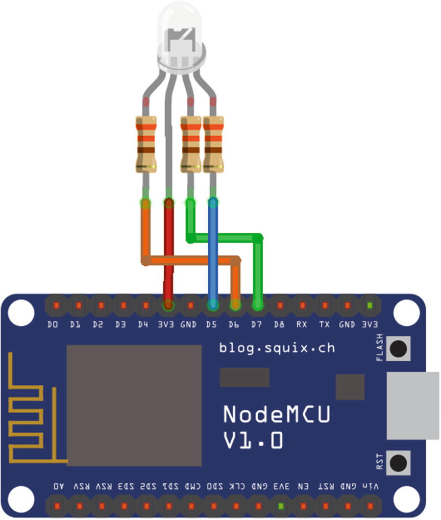
This chapter provides wiring tables and diagrams for most sensors and actuators used in the examples. The wiring diagrams show the wiring for NodeMCU boards and therefore NodeMCU pin numbers, such as D6 or D7. These labels don’t necessarily match the GPIO number used in code. If you’re using a different development board, make sure you look at the wiring tables, which provide the GPIO number—for example, GPIO12 or GPIO13—along with the NodeMCU pin numbers in parentheses. All development boards label pins differently, so you have to map the pins accordingly. The Moddable development boards are labeled with “GP” followed by the GPIO number used in code—for example, GP12 or GP13—so if the wiring table says a pin should be wired to GPIO12, plug it into the pin labeled GP12 on the Moddable boards.
Troubleshooting Wiring Issues
An error is thrown. This is common and is generally the easiest issue to fix. For example, if you swap the SDA and SCL pins of an I2C sensor, you’ll get errors when reading and writing. Take advantage of xsbug and use the error messages to diagnose your issue. Sometimes you just have to fix your wiring; other times you may have a faulty sensor or actuator.
The application works but gives unexpected results. This is also common, but it can be hard to catch. For example, if you plug the digital pin of a sensor into the wrong pin on your development board, the application reads from a pin that’s not connected to anything; it doesn’t throw an error but it does give unexpected results. If you’re pressing a button and the application isn’t responding as expected, or you’re writing to a pin of a tri-color LED and the color isn’t updated, double-check your wiring.
You destroy your sensor or actuator. This is less common than the first two issues, but it can happen. For example, powering a sensor with 5V when it’s designed to accept 3.3V can damage the electronics on the sensor.
Blinking an LED
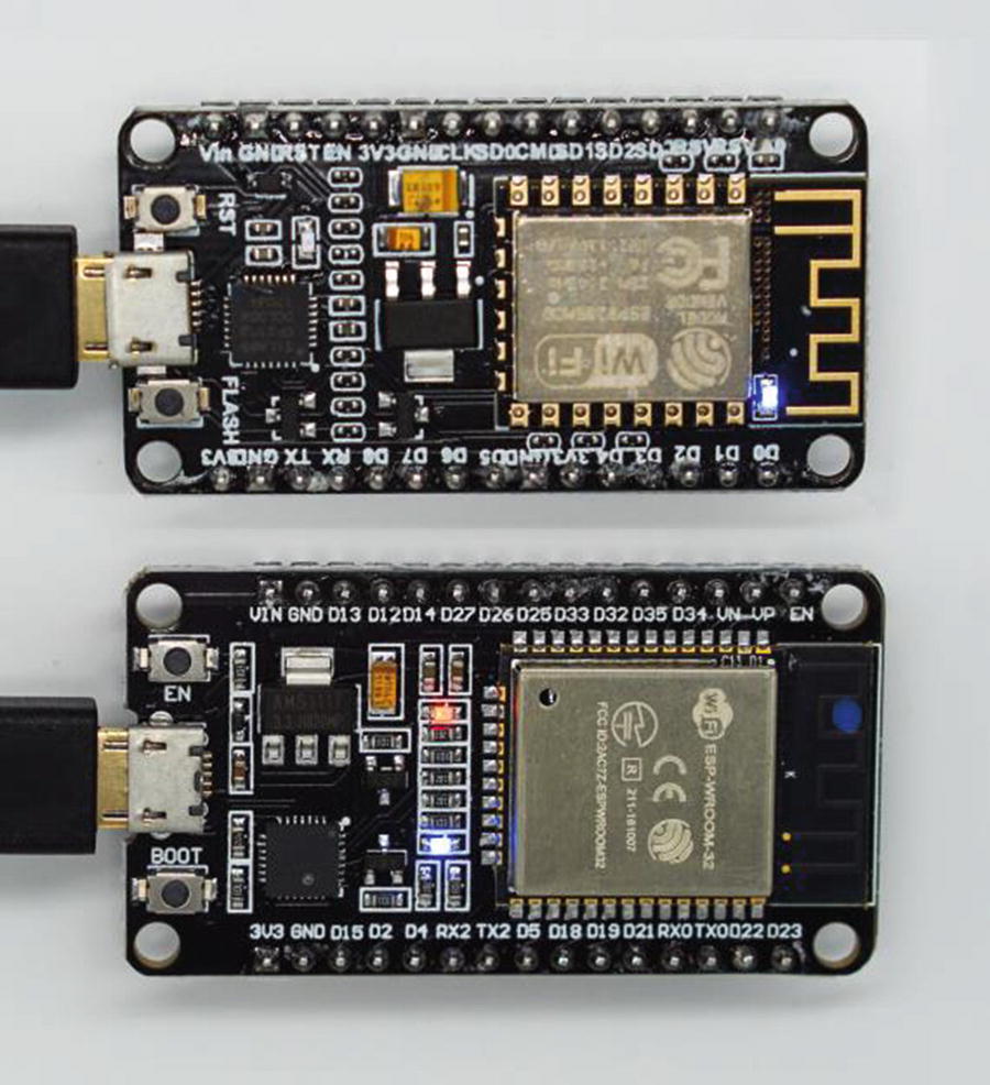
On-board LED on ESP8266 (top) and ESP32 (bottom)
Listing 6-2.
Using an instance of Digital is more efficient for writing than using the static Digital.write method ; the constructor initializes the pin once, whereas Digital.write must initialize it on each write. Digital.write is convenient for infrequent writes, but if your project writes to a digital output frequently, create an instance once and write to it instead.
Reading a Button
Buttons are a simple way to add physical input to projects. The ESP32 and ESP8266 NodeMCU modules have two buttons built in. One of the buttons is wired to digital pin 0 and may be used as a digital input in your projects; this button is labeled FLASH, BOOT, or IO0, depending on which module you have.
Listing 6-4.
Other Digital Input Modes
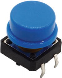
Tactile button
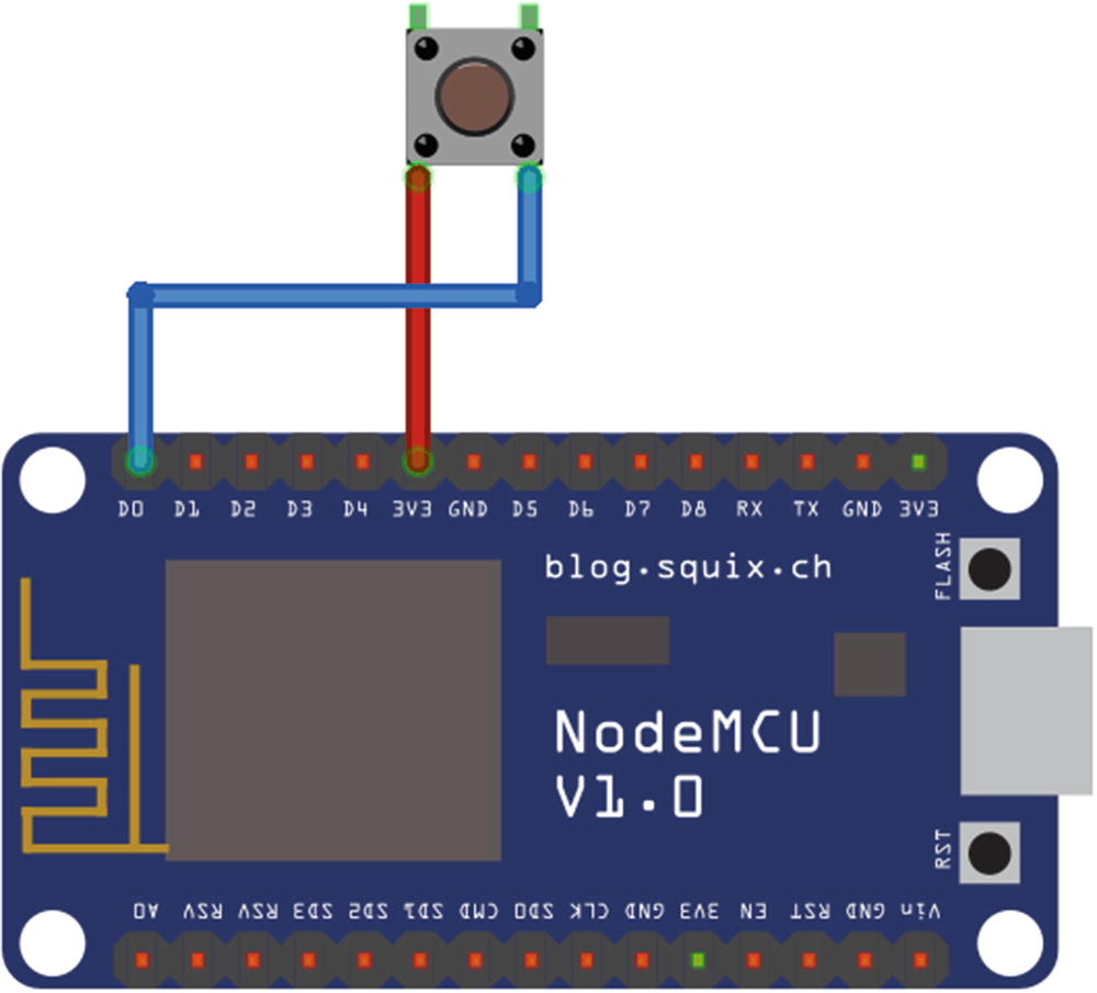
The $EXAMPLES/ch6-hardware/external-button example has the same functionality as the button example, but it works with a button like the one in Figure 6-2 rather than the built-in button. If you want to run this example, first follow the wiring instructions given here to connect it to your ESP32 or ESP8266.
ESP32 Wiring Instructions

ESP8266 Wiring Instructions
Understanding the external-button Code
The rest of the code is very similar to the rewritten button example (Listing 6-4), except for a few small changes to account for the use of the pull-down resistor.
More About Pull-Up and Pull-Down Resistors
Both the ESP32 and the ESP8266 have a built-in pull-down resistor on pin 16, which is why the external-button example runs on either one without any changes to the code. That said, you can modify it to use any pin with a built-in pull-down resistor, and other applications you build can use the other pins as well. The ESP32 has built-in pull-down resistors on all GPIO pins except pins 34–39, whereas the ESP8266 only has a built-in pull-down resistor on pin 16.
Other sensors may require a pull-up resistor. The ESP32 has built-in pull-up resistors on all GPIO pins except pins 34–39; the ESP8266 has built-in pull-up resistors on GPIO pins 1–15.
Instead of using the built-in resistors, you can also add pull-up or pull-down resistors directly to sensors. If you do this, you can use any GPIO pin, not just pins with a built-in resistor. Also note that if you do this, you should always use the mode Digital.Input . In other words, do not enable a built-in pull-down resistor if you add a pull-down resistor to the sensor itself, and likewise do not enable a built-in pull-up resistor if you add a pull-up resistor to the sensor itself.
Monitoring for Changes
You can more efficiently detect changes on the value of a digital input by using the digital Monitor class . Instead of periodic polling, it uses a feature of the microcontroller to monitor for changes. An instance of Monitor is configured to trigger on changes from 0 to 1 (that is, rising edge) and/or changes from 1 to 0 (falling edge). When the hardware detects a trigger event, the Monitor class invokes a callback function.
Listing 6-5.
The original button example uses the value and previous variables to keep track of the button’s state; using the Monitor class simplifies the code considerably because the class keeps track of the button’s state itself, notifying the application only when the state has changed.
Like the Digital constructor , the Monitor constructor takes a dictionary with pin and mode properties. It also includes an edge property specifying the events that trigger the onChanged callback; edge may be Monitor.Rising, Monitor.Falling, or Monitor.Rising | Monitor.Falling. An application must install an onChanged callback on the instance, to be invoked when the specified edge events occur.
Using the Monitor class instead of polling has advantages beyond simplifying your code. Because the class uses the microcontroller’s built-in hardware to detect changes, there’s no need to run any code to watch for changes, freeing up CPU cycles for other work. Additionally, the monitor detects changes immediately, whereas the polling approach checks for a change only every 100 milliseconds. Of course, you can poll more frequently, but that requires even more CPU cycles. Further, the polling approach misses very quick button presses that happen between reads, whereas the monitor is always active and so doesn’t miss any button presses.
Controlling a Tri-color LED
Unlike the basic on/off single-color LED in the earlier blink example, a tri-color LED (also called an RGB LED) combines three LEDs—red, green, and blue—into a single package, enabling you to precisely control both the color and the brightness. Controlling the three colors of a tri-color LED requires four pins: one to control each of the three LEDs, plus a power pin shared by all the colors.
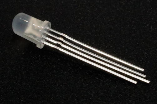
Tri-color LED
Before you run the examples, follow the instructions to set up your tri-color LED and the wiring instructions to connect it to your ESP32 or ESP8266.
LED Setup
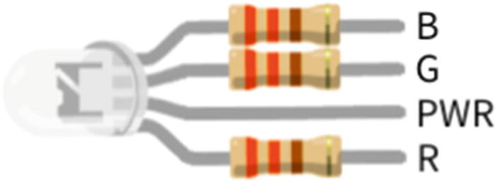
Tri-color LED with current limiting resistors
ESP32 Wiring Instructions

ESP8266 Wiring Instructions
Using Digital with a Tri-color LED
Listing 6-6.
The tri-color LED can display more than just the primary and secondary colors of black, white, red, green, blue, magenta, cyan, and yellow. To achieve that, you need more control than simply turning the red, green, and blue LEDs on and off; you need to be able to set them to values between on and off—that is, between 0 and 1. A digital output can’t do that, since its output is always either 0 or 1. In the next section, you’ll learn how to overcome this limitation.
Using PWM with a Tri-color LED
To display a greater range of color and brightness, a tri-color LED may instead be controlled using pulse-width modulation, or PWM, a special type of digital signal commonly used in motors and LEDs, including tri-color LEDs. PWM is roughly equivalent to an analog output but is generated using a digital signal. More specifically, the digital pin outputs a square wave with varied widths of high and low values. Taking the average of these high and low pulses over time creates a power level between the high and low values, proportional to the pulse widths. The result is that instead of being limited to 0 and 1 as output values, you can output any value in between.
Listing 6-7.
Listing 6-8.
Rotating a Servo
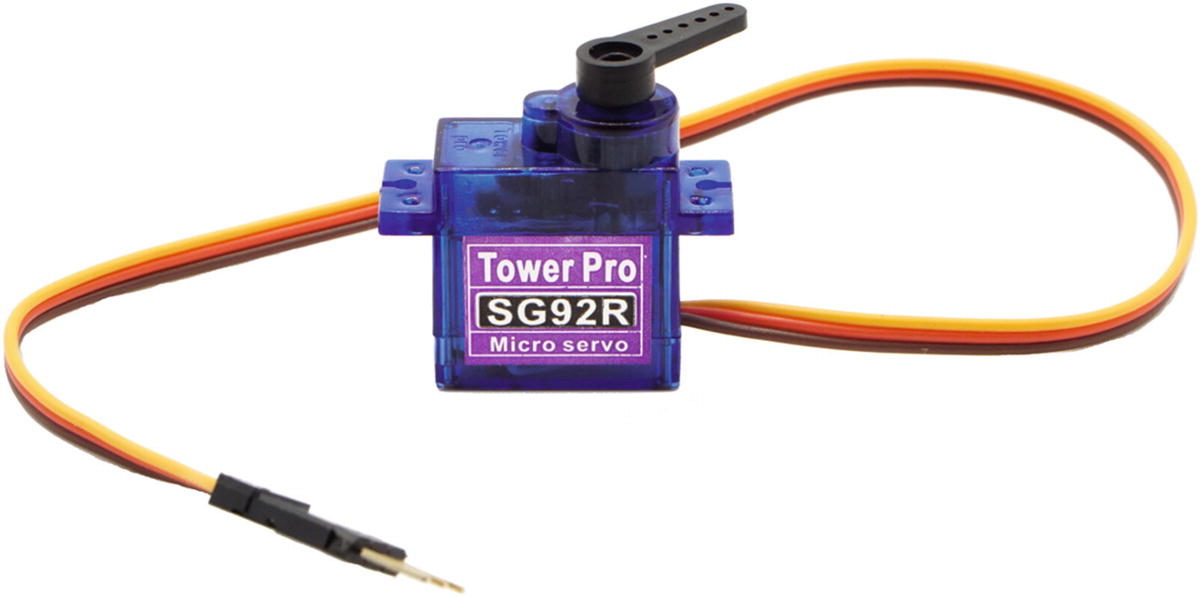
Micro servo from Adafruit
Servos are configured with the Servo class , which uses digital pins to control servo motors.
The $EXAMPLES/ch6-hardware/servo example rotates a servo from 0 degrees up to 180 degrees, 2.5 degrees at a time. Before you run the example, follow the wiring instructions given here to connect it to your ESP32 or ESP8266.
ESP32 Wiring Instructions

ESP8266 Wiring Instructions

Understanding the servo Code
Listing 6-9.
It takes time for the servo to rotate to a new position; the amount of time depends on the servo you’re using. Depending on the servo, using a shorter interval may not make the servo rotate faster but instead may result in a confused behavior as the servo does its best to keep up with the changes, which are coming in faster than it can operate.
The Servo class also has a writeMicroseconds method , which allows for greater precision by letting you provide the number of microseconds (instead of degrees) for the signal pulse. The range of acceptable values varies from servo to servo; setting the pulse length to a value that’s too low or too high can break the servo, so be sure to check your servo’s datasheet.
Getting the Temperature
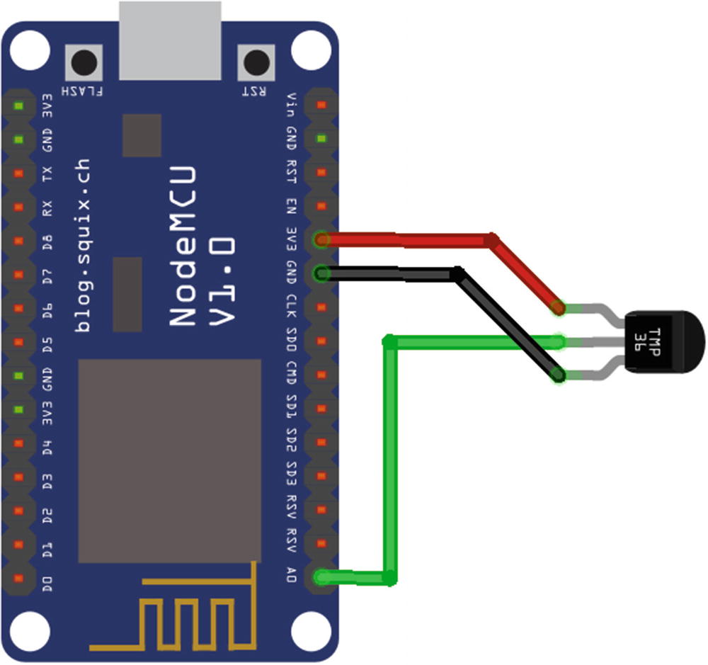
The TMP36 (Figure 6-12) uses an analog value to communicate the temperature. The simpler of the two sensors, it has only a single output—an analog output that connects to the analog input of a microcontroller—and has no configuration options. It’s available from SparkFun (product ID SEN-10988) and Adafruit (product ID 165).
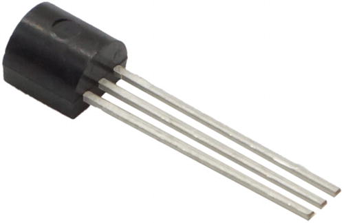
TMP36 sensor
The TMP102 (Figure 6-13) uses the I2C bus to communicate the temperature. It connects using the I2C hardware protocol, which is considerably more complex to work with than an analog input but enables the sensor to offer additional functionality and configuration options. It’s available from SparkFun (product ID SEN-13314).

TMP102 sensor
This section also explains how to use a sensor’s datasheet to understand the data provided by the sensor and convert it to a human-readable format.
TMP36
The $EXAMPLES/ch6-hardware/tmp36 example reads the temperature from a TMP36 sensor and traces the value in degrees Celsius to the debug console. Before you run the example, follow the wiring instructions given here to connect the TMP36 to your ESP32 or ESP8266.
ESP32 Wiring Instructions

ESP8266 Wiring Instructions
Understanding the tmp36 Code
Unlike other hardware protocol classes, the Analog class is never instantiated. It provides only one static method: a read method that samples the value of the specified pin, returning a value from 0 to 1023. The tmp36 example calls the read method and converts the returned voltage to the temperature.
The excellent Adafruit tutorial for the TMP36 (learn.adafruit.com/tmp36-temperature-sensor/overview) provides the following formula to convert the voltage to the temperature:
Temp in °C = [(Vout in mV) – 500] / 10
If you’re running on Moddable Two, you’ll need to change the pin number from 0 to 7 due to the difference in wiring.
The TMP36 is designed to accurately measure temperatures between –40°C and +125°C. For temperatures outside this range, it returns readings but with less accuracy. The analog input has 10 bits of resolution, allowing for readings with an accuracy of about 0.25°C. This accuracy is sufficient for many purposes, but not all; as described next, the TMP102 temperature sensor provides greater resolution for temperature measurements.
TMP102
The $EXAMPLES/ch6-hardware/tmp102 example reads the temperature from a TMP102 sensor and traces the value in degrees Celsius to the debug console. Before you run the example, follow the wiring instructions given here to connect the TMP102 to your ESP32 or ESP8266.
This section refers to the TMP102 schematic and the TMP102 datasheet, both of which can be found on the TMP102 product page on SparkFun’s website: sparkfun.com/products/13314.
ESP32 Wiring Instructions

ESP8266 Wiring Instructions

Understanding the tmp102 Code
The tmp102 example retrieves temperature data from the TMP102 and converts it to degrees Celsius for output to the debug console. This particular example is worth a careful look because it introduces the I2C hardware protocol, which is used in a vast number of sensors. I2C is a serial protocol for connecting multiple devices to a single two-wire bus.
Once you learn the fundamentals of working with I2C in JavaScript, you can often quickly write the code to communicate with a new sensor based on a review of the hardware datasheet or a sample implementation, such as an Arduino sketch. An alternative method, using the SMBus subset of I2C, is discussed in the next section. Understanding how to use I2C and SMBus will enable you to explore the many options of a huge array of available sensors.
Note that this chapter introduces many, but not all, of the capabilities of the TMP102. The datasheet is the best way to learn about the capabilities of any sensor. Further reading on the TMP102 shows that it includes features designed for use in thermostats, for example.
One of the features that make I2C popular is that, because it’s a bus, it allows several different sensors to be connected to the same two microcontroller pins. Each sensor has a unique address, enabling them to be accessed independently. Using a bus for this hardware protocol reduces the total number of pins needed to connect multiple sensors, which is valuable because often the number of available pins is limited.
TMP102 registers
Register # | Register Name | Purpose |
|---|---|---|
0 | Temperature | Read the most recent temperature |
1 | Configuration | Read or set options for temperature conversion rate, power management, and so on |
2 | TLOW | Read or set the low temperature when using the built-in comparator |
3 | THIGH | Read or set the high temperature when using the built-in comparator |
The read method returns the bytes in a Uint8Array instance named value. It can read up to 40 bytes from the target device, although most I2C reads are just a few bytes.
Listing 6-10.
Using SMBus
The System Management Bus, or SMBus , protocol is built on top of I2C. It uses a subset of the methods defined by I2C to formalize a convention used by many register-based I2C devices, including the TMP102. As mentioned previously, the TMP102 uses four registers to read and write values between the sensor and the microcontroller. To read from or write to a register, you first send the register number, then send the read or write command.
The readWord method takes two arguments: first the register to read and then true if the two bytes are in big-endian order or false if little-endian (the default). Because the first byte returned here is the most significant byte, the value is big-endian, so the second argument is true. Since the two bytes have already been combined into an integer, all that remains is to shift right by 4 bits to generate the 12-bit value.
The SMBus class provides readByte to read a single byte and readBlock to read a specified number of bytes. It also provides the corresponding write methods writeByte, writeWord, and writeBlock.
Configuring the TMP102
The TMP102 is able to support a variety of configuration options because it communicates over I2C, a flexible and extensible hardware protocol. This section discusses four such options.
Note that to simplify the code, the examples in this section use the SMBus subclass of I2C instead of I2C directly.
Reading Higher Temperatures with Extended Mode
The TMP102 can measure temperatures up to 150°C, but to do so requires increasing the resolution from the default of 12 bits to 13 bits, which is done by enabling extended mode. This mode, like most of the options of the TMP102, is controlled by the 16-bit configuration register, which is register 1. To enable extended mode, you set the EM bit in the configuration register to 1.
Listing 6-11.
In your own IoT product, you may already know the value of the configuration register, without needing to read it. In that case, you can set it directly, without the initial read.
Listing 6-12.
Setting the Conversion Rate
The conversion rate is the number of times a second the TMP102 completes a temperature measurement and updates the value in the temperature register. The TMP102 takes about 26 milliseconds to complete a temperature measurement. By default, the conversion rate is four times per second. During the 224 milliseconds between when a reading has been taken and the next reading is begun, the TMP102 enters a low power mode, reducing energy consumption by about 94%, from 40 μA to 2.2 μA.
Knowing the conversion rate is important to your application. If you read the temperature from the sensor more frequently than it’s updated, you receive the same value, using limited CPU cycles unnecessarily. On the other hand, if the sensor is performing temperature readings more frequently than your application requires, it’s using more energy than needed, as it generates readings that go unused.
00 – once every 4 seconds (0.25 Hz)
01 – once per second (1 Hz)
10 – four times per second (4 Hz, the default)
11 – eight times per second (8 Hz)
Listing 6-13.
Saving Energy with Shutdown Mode
Reducing the frequency of temperature conversions saves energy. However, the lowest frequency is still one conversion every 4 seconds, which may be more often than your IoT product requires. The TMP102 provides shutdown mode, which completely disables the temperature conversion hardware, reducing energy consumption to 0.5 μA. Your application can enter shutdown mode in the interval between readings and then reenable the conversion.
Listing 6-14.
Listing 6-15.
Taking One-Shot Temperature Readings
Listing 6-16.
Listing 6-17.
Listing 6-18.
One-shot mode has another interesting use. Since reading a temperature takes about 26 milliseconds, in theory about 38 readings may be taken per second. However, recall that the maximum conversion rate supported by the configuration register is eight times per second. Using continuous, back-to-back one-shot readings enables temperature readings to be taken as quickly as the hardware supports, which is valuable for situations where you want to precisely capture how the temperature changes over time.
Conclusion
Now that you understand the basics of some hardware protocols and know how to interact with some sensors and actuators, there’s a lot you can do to make the simple examples provided more interesting. For example, you could make actuators respond to the input from sensors, or take what you learned in Chapter 3 about communicating with cloud services and use it to stream data from your sensors to the cloud. In Chapters 8, 9, and 10, you’ll learn how to work with a touch screen, which is great for displaying sensor data and building user interfaces that work with hardware.
Countless other sensors and actuators are available online and in electronics stores. This chapter used some from SparkFun and Adafruit, both of which are excellent resources for beginners to electronics. In addition to offering many sensors and actuators and their datasheets, they also provide tutorials for many of their products, which are helpful starting points for writing your own JavaScript modules to interact with them.