This chapter takes you through gathering all the hardware and software required for this book and running your first JavaScript application on a microcontroller. Along the way, the chapter also shows how to use the helpful features of xsbug, the JavaScript source-level debugger.
Installing all the software tools and setting up your development environment takes a little time, but once you can run one example you’ll be ready to run any example in this book. You’ll also have everything you need to begin writing your own applications using the Moddable SDK.
Hardware Requirements
A computer with a USB port (macOS Sierra version 10.12 or later, Windows 7 Pro SP1 or later, or Linux)
A Micro USB cable (high-speed, data sync–capable)
An ESP32 NodeMCU module or ESP8266 NodeMCU module
All the examples run on the ESP32 or the ESP8266, with the exception that the examples using Bluetooth Low Energy (BLE), as discussed in Chapter 4, run only on the ESP32, because the ESP8266 doesn’t support BLE. If you’re interested in experimenting with the BLE examples in this book, you’ll need to use an ESP32.
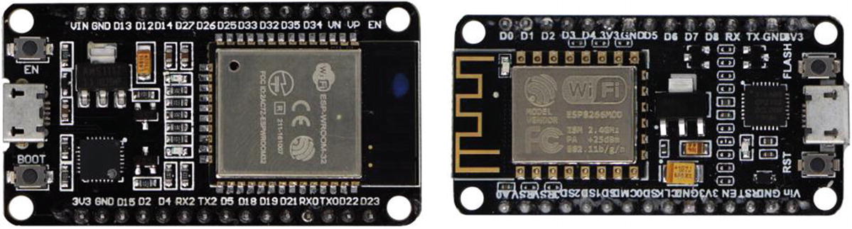
ESP32 (left) and ESP8266 (right)
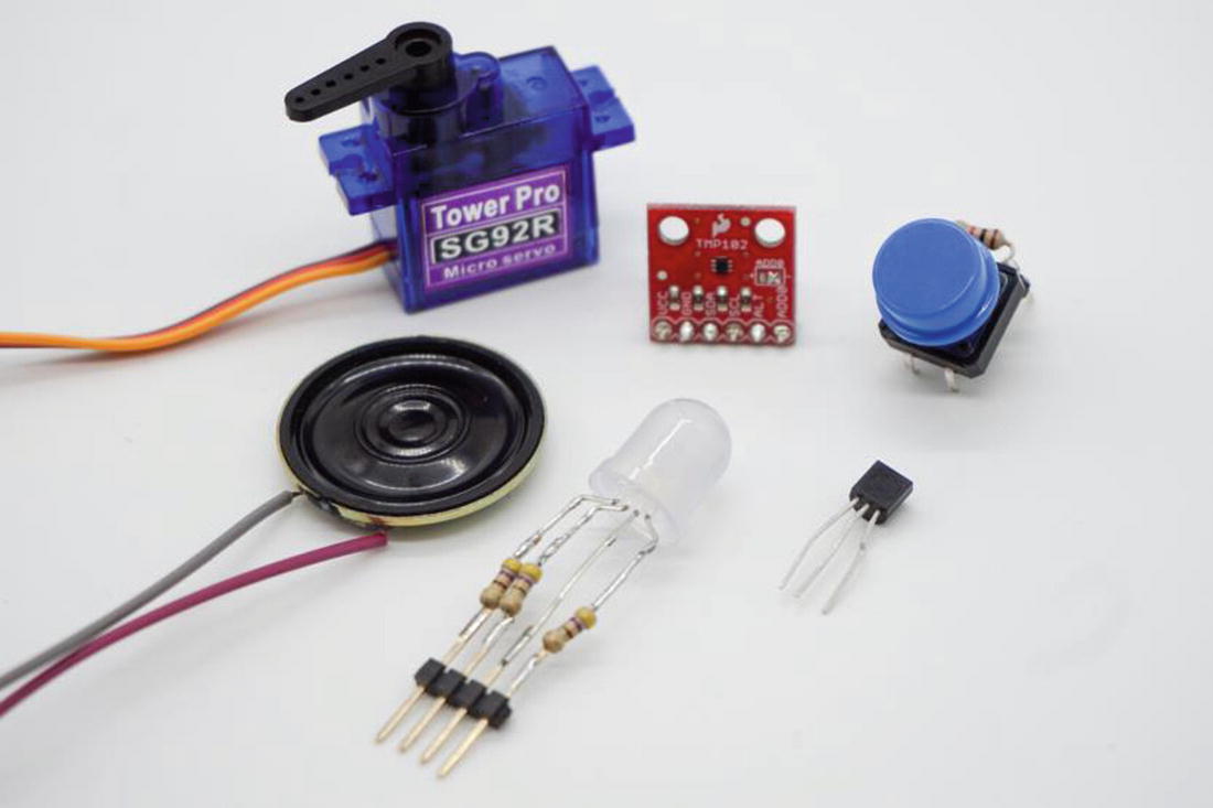
Tactile button
Tri-color LED (common anode)
Three 330 Ohm resistors
Micro servo
TMP36 temperature sensor
TMP102 temperature sensor
Mini metal speaker (8 Ohm, 0.5W)
Jumper wires
An ILI9341 QVGA touch display (Figure 1-3), which is available on eBay and elsewhere online; search for “spi display 2.4 touch” and you should find several inexpensive options. Note that although this display works well, there are many other choices. The Moddable SDK includes built-in support for several other displays of varying cost and quality; see the documentation/displays directory of the Moddable SDK for more information.
A breadboard.
Male-to-female jumper wires.
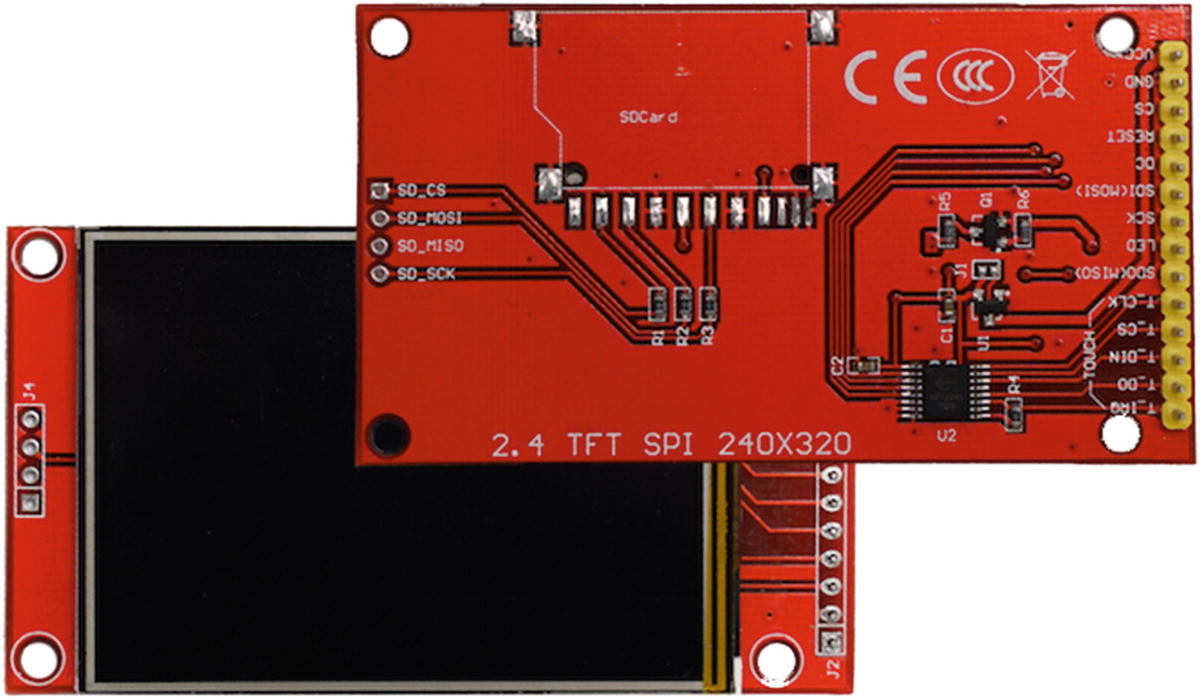
ILI9341 QVGA touch display
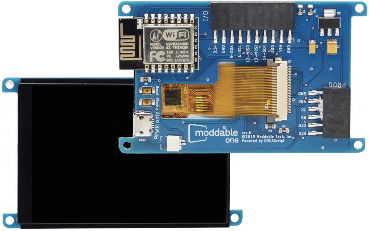
Moddable One
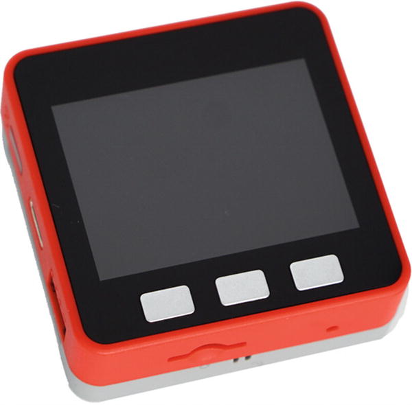
M5Stack FIRE
Software Requirements
Code editor
Example code files
Moddable SDK
Build tools for the ESP32 and/or ESP8266
You can choose whichever code editor you prefer. There are many JavaScript-friendly editors, including Visual Studio Code, Sublime Text 3, and Atom.
The next sections explain how to download the example code files and set up the Moddable SDK and build tools for your device.
Downloading the Example Code
All the examples are available at https://github.com/Moddable-OpenSource/iot-product-dev-book. You can download the example code using the git command line tool.
In this book, commands that you enter on the command line are preceded by a > symbol. This symbol is not part of the command; it’s included only to clarify where each separate command begins.
You also need to set the EXAMPLES environment variable to point at your local copy of the examples repository, as follows:
- On macOS/Linux:> export EXAMPLES=~/Projects/iot-product-dev-book
- On Windows:> set EXAMPLES=C:Users<username>Projects iot-product-dev-book
Setting Up Your Build Environment
Before building and running the examples, follow the instructions in the “Moddable SDK – Getting Started” document in the documentation directory of the Moddable SDK. This document provides step-by-step instructions for installing, configuring, and building the Moddable SDK for macOS, Linux, and Windows, as well as instructions for installing tools you need in order to work with the ESP32 and ESP8266.
Using xsbug
xsbug debugger
Similar to other debuggers, xsbug supports setting breakpoints and browsing source code, the call stack, and variables. It also provides real-time instrumentation to track memory usage and to profile application and resource consumption.
When you’re developing for a microcontroller, the build system automatically opens xsbug before launching your application on the target device.
- On macOS:> open $MODDABLE/build/bin/mac/release/xsbug.app
- On Windows/Linux:> xsbug
Important Features for Examples in This Book
Machine tabs – Each XS virtual machine connected to xsbug gets its own tab in the upper left of the window (as highlighted by the dashed border in Figure 1-7). Clicking a tab changes the left pane to the machine tab view, where you can view instrumentation, use control buttons, and more.
Control buttons – These graphically labeled buttons (highlighted by the dotted border in the figure) at the top of the machine tab view control the virtual machine. From left to right, they are Kill, Break, Run, Step, Step In, and Step Out.
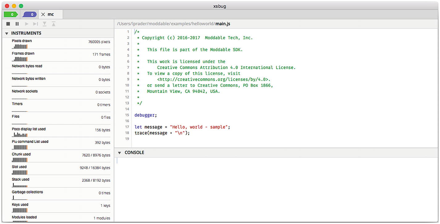
Console – It’s often useful to be able to view diagnostic messages during execution of an application. The trace function writes messages to the debug console in the bottom right of xsbug.
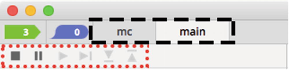
xsbug machine tabs and control buttons
See the xsbug document in the documentation/xs directory of the Moddable SDK for full documentation of all the features of xsbug.
Running Examples
The examples in the repository for this book are organized by chapter, each one having several examples. To make it faster to build and launch the examples, each chapter has its own host, which contains the software environment needed to run the examples for that chapter; the host is the collection of JavaScript modules, configuration variables, and other software available for your application to use. Because space is very limited in microcontrollers, it isn’t possible to have a single host that contains all the modules used in the examples in this book.
You can think of the host as essentially the base application. The web browser is the host when you run JavaScript in a web browser; Node.js is the host when you run JavaScript on a web server.
Installing the host separately, rather than installing the host and example together, significantly speeds up development, by minimizing the amount of software that needs to be downloaded. Installing a host on your device typically takes between 30 and 90 seconds. Once that’s done, you can install most examples in just a few seconds, because the host already contains the device firmware and JavaScript modules required by the examples.
The next sections walk you through the entire process of installing a host and then an example, starting with helloworld. Note that in the context of this book, installing an application causes the application to then run on the device.
Installing the Host
The first step is to flash the device to install the host. The source code for each chapter’s host is available to read in the host directory , if you’re curious. To use the host, all you really need to know is that it includes all the modules necessary for the corresponding examples.
You use the mcconfig command line tool to flash the device.
mcconfig
The mcconfig command line tool builds and installs applications on microcontrollers or in the simulator. The commands to use to install this chapter’s host on each supported platform are provided here.
- On macOS/Linux:> cd $EXAMPLES/ch1-gettingstarted/host> mcconfig -d -m -p esp32
- On Windows:> cd %EXAMPLES%ch1-gettingstartedhost> mcconfig -d -m -p esp32
- On macOS/Linux:> cd $EXAMPLES/ch1-gettingstarted/host> mcconfig -d -m -p esp
- On Windows:> cd %EXAMPLES%ch1-gettingstartedhost> mcconfig -d -m -p esp
Confirming the Host Was Installed
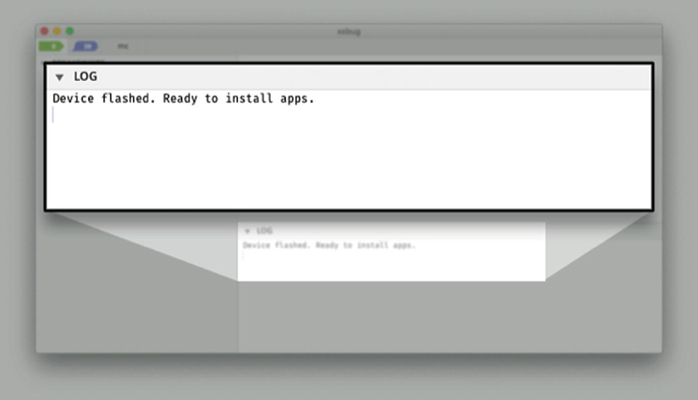
Message from host in xsbug
Installing helloworld
The debugger statement, which halts execution and breaks into xsbug.
The trace function, which writes messages to the debug console. Note that trace doesn’t automatically add a newline character ( ) at the end of the message. This enables you to use several trace statements to generate the output of a single line. Be sure to include the newline character at the end of the line so that the text displays properly in xsbug.
You use mcrun to install examples.
mcrun
The mcrun command line tool builds and installs additional JavaScript modules and resources that change the behavior or appearance of Moddable applications on microcontrollers or in the simulator. Both mcconfig and mcrun build scripts and resources. Unlike mcrun, mcconfig also builds native code. In JavaScript terms, mcconfig builds the host.
After you install an example using mcrun, the device reboots. This relaunches the host, which in turn runs the example you installed.
- On macOS/Linux:> cd $EXAMPLES/ch1-gettingstarted/helloworld> mcrun -d -m -p <platform>
- On Windows:> cd %EXAMPLES%ch1-gettingstartedhelloworld> mcrun -d -m -p <platform>
Finishing Up
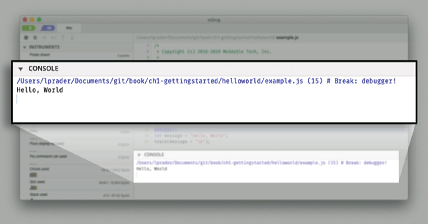
Hello, World written to console in xsbug
If everything goes well, you can move on to the “Conclusion” section of this chapter if you’re working with a bare NodeMCU board. If you want to add a display—which is highly recommended—continue with the “Adding a Display” section instead.
If you ran into issues, see the next section.
Troubleshooting
When you’re trying to install an application, you may experience roadblocks in the form of errors or warnings; this section explains some common issues and how to solve them.
Device Not Connected/Recognized
Your device is not plugged into your computer. Make sure it’s plugged in when you run the build commands.
You have a USB cable that is power only. Make sure you’re using a data sync–capable USB cable.
The computer does not recognize your device. To fix this problem, see the instructions that follow for your operating system.
macOS/Linux
Then plug in the device and repeat the same command. If nothing new appears, the device isn’t being seen. Make sure you have the correct VCP driver installed.
Windows
Check the list of USB devices in Device Manager. If your device shows up as an unknown device, make sure you have the correct VCP driver installed.
Incompatible Baud Rate
You have a faulty USB cable.
You have a USB cable that does not support higher baud rates.
You’re using a board that requires a lower baud rate than the default baud rate that the Moddable SDK uses.
- 1.
If you’re working with an ESP32, open moddable/tools/mcconfig/make.esp32.mk; if an ESP8266, open moddable/tools/mcconfig/make.esp.mk.
- 2.
Find this line, which sets the upload speed to 921,600:
- 3.
Set the speed to a smaller number. For example:
Device Not in Bootloader Mode
- 1.
Unplug the device.
- 2.
Hold down the BOOT button (circled in Figure 1-10).
- 3.
Plug the device into your computer.
- 4.
Enter the mcconfig command.
- 5.
Wait a few seconds and release the BOOT button.
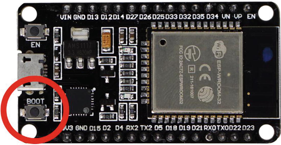
BOOT button on ESP32
Adding a Display
Show more information than a few blinking lights
Create modern user interfaces
Add functionality
The examples in this book are designed for a display with 240 x 320 or 320 x 240 resolution (for example, QVGA). These displays are typically between 2.2" and 3.5" in size and were common in early smart phones. Displays of other sizes may be connected to these microcontrollers, but this size is a good match for the capabilities of these microcontrollers.
The following sections show how to connect the ILI9341 QVGA touch display to the ESP32 or ESP8266. If you’re using a development board like the Moddable One or Moddable Two, you can skip to the “Installing helloworld-gui” section.
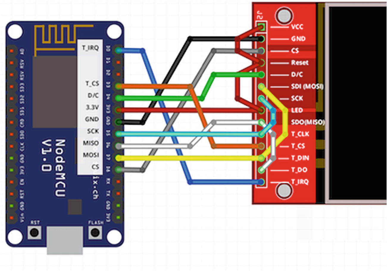
Connecting a Display to the ESP32
Wiring to connect display to ESP32
ILI9341 Display | ESP32 |
|---|---|
SDO/MISO | GPIO12 |
LED | 3.3V |
SCK | GPIO14 |
SDI/MOSI | GPIO13 |
CS | GPIO15 |
DC | GPIO2 |
RESET | 3.3V |
GND | GND |
VCC | 3.3V |
T_DO | GPIO12 |
T_DIn | GPIO13 |
T_CLK | GPIO14 |
T_IRQ | GPIO23 |
T_CS | GPIO18 |

Wiring diagram for connecting display to ESP32
Connecting a Display to the ESP8266
Wiring to connect display to ESP8266
ILI9341 Display | ESP8266 |
|---|---|
SDO/MISO | GPIO12 |
LED | 3.3V |
SCK | GPIO14 |
SDI/MOSI | GPIO13 |
CS | GPIO15 |
DC | GPIO2 |
RESET | 3.3V |
GND | GND |
VCC | 3.3V |
T_DO | GPIO12 |
T_DIn | GPIO13 |
T_CLK | GPIO14 |
T_IRQ | GPIO16 |
T_CS | GPIO0 |
Wiring diagram for connecting display to ESP8266
Installing helloworld-gui
The helloworld-gui example is a version of helloworld that displays text on the screen. If you wired a display to a device yourself, reflashing the device with the helloworld-gui application is a good way to test whether the wiring is correct.
The commands to use are very similar to the ones used to install helloworld. The only difference is the platform identifier. The platform identifier tells the build system to include the proper display and touch drivers. If you’re using a Moddable One, the platform identifier is esp/moddable_one; for a Moddable Two, it’s esp32/moddable_two. If you added a display according to the instructions in the preceding sections, the platform identifier is either esp32/moddable_zero or esp/moddable_zero.
- On macOS/Linux:> cd $EXAMPLES/ch1-gettingstarted/helloworld-gui> mcconfig -d -m -p <platform>
- On Windows:> cd %EXAMPLES%ch1-gettingstartedhelloworld-gui> mcconfig -d -m -p <platform>
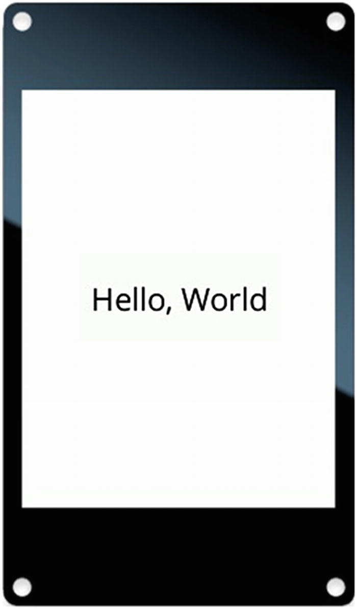
Graphical helloworld application
Conclusion
Now that your development environment is set up and you’re familiar with the process of installing this chapter’s examples on your device, you’re ready to try some more examples!
At this point, you have all the materials and skills you need to follow along with Chapters 2 through 10. These chapters are independent of each other, so you can read them in any order. As you start working with the examples in a chapter, be sure to install that chapter’s host or you’ll encounter errors when launching the examples. Once you feel comfortable with the APIs of the Moddable SDK, you can move on to Chapter 11, which covers more advanced topics.