Poco, a rendering engine for embedded systems that you can use to draw to displays
Piu, an object-oriented user interface framework that uses Poco for drawing and simplifies the process of creating complex user interactions
With this knowledge, you’ll be ready to begin building IoT products with built-in displays—and to explain to your friends and colleagues that this goal is in reach for your products.
Why Add a Display?
Far more information is conveyed by a display than by a few pulsing status lights or alert sounds. A display shows the user what the product is doing in detail, and if there’s a problem it tells the user what went wrong.
A display makes it possible to include complete configuration options for all the capabilities of the product. This level of precision for configuration is generally not possible with a few buttons and knobs.
A display enables the user to perform sophisticated interactions directly, with no other device required. Compare this to the user’s downloading and installing a mobile app to interact with the product and pairing the app to the product before being able to begin configuring it.
The graphical richness of a display lets you combine images with animations to bring style and character to the product, making it more enjoyable for the user and reinforcing the brand image of the manufacturer.
The display itself is expensive. A small touch screen can easily cost $20 before adding the microcontroller and communication components.
The software to interact with the display requires adding more RAM, and the graphics assets (images and fonts) for building a user interface require adding more storage.
A special microprocessor with hardware graphics acceleration—that is, a GPU—is needed to achieve acceptable frame rates for animations.
Graphics programming for microcontrollers requires highly specialized skills, making it more difficult to find qualified engineers and more expensive to hire them.
The licensing costs for graphics and user interface SDKs for microcontrollers are too high.
Preparing graphics assets for embedded systems is time-consuming and error-prone.
These were all valid reasons in the past, but today the situation is quite different. Unfortunately, most product planners, designers, and engineers working on IoT products are not aware that it’s possible to get a touch screen, microcontroller, RAM, and ROM to deliver a beautifully rendered modern user interface for under $10, even for products in very low volume (comfortably under 10,000 units). Further, that same microcontroller can also provide Wi-Fi and Bluetooth support. The software and asset concerns are addressed by Poco and Piu.
Overcoming Hardware Limitations
The hardware in today’s computers and mobile phones is designed to perform extremely complex graphical operations with amazing efficiency. This remarkable performance is achieved through a combination of sophisticated hardware and software. It should be no surprise that a typical microcontroller does not have that same graphics hardware and lacks the speed and memory to run the same complex graphics algorithms.
The natural consequence of these differences is that when IoT products powered by microcontrollers do include a display, the user interfaces they provide often appear quite primitive, like those of computers and video games from the dawn of the personal computer era in the 1980s and early 1990s. In some ways, that makes sense, because, like early personal computers and video games, these microcontrollers are considerably less powerful than modern computers. But an ESP32 today runs six times faster than the microprocessor in the top-of-the-line 1992 Macintosh IIfx, so there’s enough performance in a modern microcontroller to match or exceed the results of this early hardware.
The Moddable SDK achieves great graphics results on a microcontroller by applying techniques used on early hardware, before modern high-speed display buses, plentiful memory, and GPUs. The implementations are inspired by classic techniques that have successfully been used for computer animation, video games, fonts, and more. Modern microcontrollers are still memory-constrained, but they’re faster, so more calculations are possible. This makes some techniques possible that were not on older hardware.
The details of how these techniques work are beyond the scope of this book. All of the code that implements them is available to you in the Moddable SDK if you’re interested in learning more. This book focuses on how to use these capabilities to build a great user interface for your product.
Pixel Rate Impacts Frame Rate
In modern mobile apps and web pages, the frame rate is the fundamental measure of graphics performance. Higher frame rates provide smoother animation. The GPU in computers and mobile phones is so powerful that it’s able to update every pixel of the display on every frame. For a variety of reasons, a microcontroller just can’t do the same; however, it’s possible to achieve animations at 30 or even 60 frames per second (fps).
Because a microcontroller cannot render a high frame rate when updating the entire display, the solution is to update only a subset of the display. You can design your user interface so that only relatively small parts of the display are updated at any one time. This significantly reduces the work required of the microcontroller, so the user sees a smooth, high frame rate animation just as on a mobile app or web page.
To achieve a high frame rate using a microcontroller, it’s helpful to think in terms of pixel rate—the number of pixels updated per second. The ESP32 and ESP8266 use a SPI bus to communicate with the display, and this connection runs at 40 MHz, providing a pixel rate of about 1,000,000 pixels per second, about 15 fps. Achieving the full theoretical pixel rate is generally not possible because of other factors; still, if your application updates only about 40% of the pixels in each frame—a pixel rate of about 30,000 pixels per frame—it can achieve a reliable frame rate of 30 fps. On the QVGA (320 x 240) displays used in this book, 30,000 pixels is about 40% of the total display area, which is more than enough motion to create a smooth, compelling user interface. Updating only 10,000 pixels per frame achieves 60 fps.
You might expect that the area of the screen updated on each frame must be a single rectangle. That would limit the design possibilities by limiting motion to one area of the display. Fortunately, though, this isn’t the case. As you’ll soon learn, you can have several different areas updating simultaneously, which can give the user the impression of motion on the full screen even though only a fraction of the actual pixels are changing.
Drawing Frames
- 1.
You tell Poco when you’re starting to draw.
- 2.
When you call drawing functions, they don’t draw immediately but rather are added to a list of drawing commands.
- 3.
When you tell Poco you’re done drawing, it executes all the drawing commands.
Retained mode rendering eliminates flicker. For example, when you draw the background of the screen in an immediate mode renderer, all the pixels of the screen are drawn in the background color; when you then draw the controls, text, and pictures that make up the user interface, the user may first see the background screen without these user interface elements, causing a distracting momentary flicker. Because retained mode rendering executes all drawing commands before sending the result to the screen, it combines the background erase with the drawing of the user interface elements on the microcontroller before transmitting them to the display, thus eliminating the flicker.
Retained mode improves performance by reducing the number of pixels transmitted from the microcontroller to the display. Consider that in every user interface there are some overlapping pixels—for example, the background of a button and its text label. In an immediate mode renderer, the overlapping pixels are sent to the display twice, whereas in a retained mode renderer each pixel is sent only once per frame. Because it’s much faster to render a pixel than to transmit it to the display, this increases the overall pixel rate.
Retained mode improves rendering quality by enabling efficient pixel blending. Modern computer graphics make heavy use of blending to smooth the edges of objects—for example, to anti-alias fonts to eliminate sharp edges (“jaggies”). This is one reason that text on today’s computers and mobile phones looks so much crisper than screen text did in the 1980s. Blending is computationally more complex, and there’s enough performance to do it because the microcontrollers are so much faster; however, blending also requires access to the pixel behind the pixel you’re currently drawing. In typical microcontroller hardware, the previous pixel is stored in the display’s memory, not the microcontroller’s memory, making it either entirely unavailable or impractically slow to access. The retained mode renderer, because it only transmits pixels to the display when they’re fully rendered, always has the current value of the pixel available in memory and so is able to perform blends efficiently.
There are other advantages of retained mode renderers, but these three should be enough to convince you that the memory and complexity costs justify using a retained mode renderer like Poco instead of the more common immediate mode renderer. The quality of the user interface rendering is so much higher that users have the impression they’re using a higher-quality product—one that belongs alongside their computer and phone rather than in a computer history museum.
Scanline Rendering
A QVGA display has 76,800 pixels, which means that a display with 16-bit pixels requires 153,600 bytes of memory to store one full frame. The ESP8266 has about 80 KB of total memory—only enough for a half frame, if your IoT product doesn’t use any other memory! The ESP32 has much more, but still, holding an entire frame in memory uses 50% or more of the total free memory at startup. The displays used in this book include memory for a single frame, so the microcontroller doesn’t have to store the entire frame, but it does need memory in which to render the frame. To minimize the memory required, the Poco renderer implements scanline rendering , a technique that divides the frame into horizontal strips as small as a single row of pixels; after each strip is rendered, it’s immediately transmitted to the display. This approach is more complex than rendering the entire frame at once, but it reduces the rendering memory requirements for a single 16-bit QVGA display from 153,600 bytes to 480 bytes—one 240-pixel scanline at two bytes per pixel—a memory savings of 99.68%!
There’s some performance overhead for each strip rendered, so there’s a benefit to reducing the number of strips by increasing their size—but of course this also increases the memory needed. The performance benefit decreases somewhat with each line added to a strip, so increasing beyond about eight scanlines isn’t usually worthwhile. If your project has some free memory or requires the highest performance rendering, you may want to have Poco render a few scanlines at a time; the upcoming chapters explain how to configure this.
Many modern microcontrollers, including the ESP32 and ESP8266, are able to use SPI asynchronously to transmit data to the display, which means that the microcontroller can do other work while that data is being transmitted. Poco uses asynchronous SPI transmission to render the next section of the display while the previous section is being transmitted to the display, and this simple parallel processing allows for a significant performance boost. To use this technique, Poco must have enough memory to hold at least two scanlines in memory: the previously rendered scanline that’s now being transmitted and the current scanline that’s now being rendered. Because this technique provides such a significant performance increase, Poco allocates two scanlines by default.
Restricting the Drawing Area
In Poco – The feature of the Poco rendering engine that enables restricting drawing to subsections of the display is called clipping. Poco uses a single rectangle to describe the clipping area; the portion of each drawing operation that intersects this clipping rectangle is drawn, whereas any portion of the operation that falls outside the clipping rectangle is not drawn. This feature is used by Poco to implement scanline rendering (and by Piu to implement partial frame updates). It’s also available for use in your applications—for example, to draw a subset of an image.
In Piu – Updating the smallest possible area of the display increases rendering performance on microcontrollers; however, determining the smallest possible area to update is quite difficult in the general case. Poco can’t determine the optimal drawing areas for you because, being a rendering engine, it has no knowledge of what your code is drawing. Piu, on the other hand, is a user interface framework with complete knowledge of the different objects that make up your onscreen display. As a result, Piu is able to calculate the smallest possible update areas for you automatically, behind the scenes.
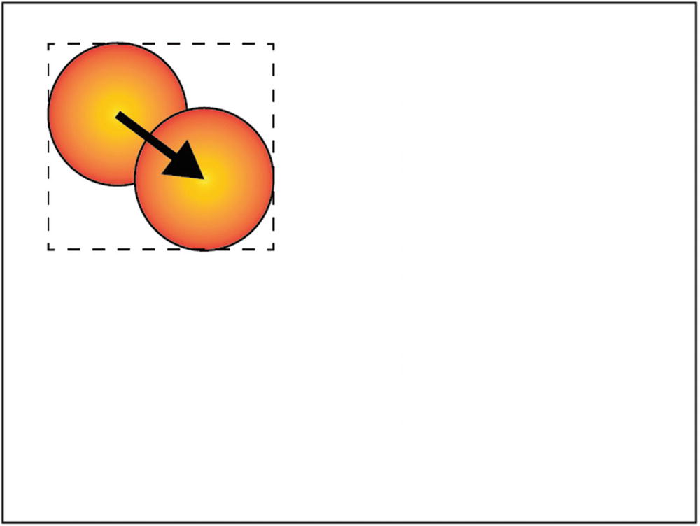
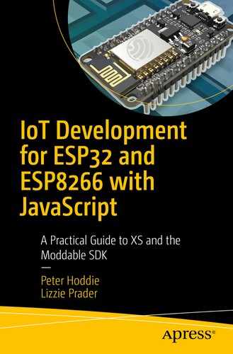
Ball moving slightly, one update rectangle
Ball moving farther, one update rectangle

Ball moving farther, two update rectangles

Ball moving slightly, three update rectangles
The calculations involved in optimizing the drawing area for a single bouncing ball are already surprisingly complex, and they would be even more complicated in an application with several bouncing balls that sometimes overlap. Piu automatically calculates the minimal set of rectangles for you; this does require time and memory, but the performance boost it gives makes it worthwhile. That’s because rendering performance is largely limited by the pixel rate of your application and Piu is automatically minimizing the pixel rate of your code.
Pixels
Every display contains pixels, but not all displays have the same kind of pixels. Pixels come in different sizes and colors. This has always been the case but is easy to forget, because nearly all modern computers and mobile devices support the same 24-bit color pixel format. Like many areas of embedded development, the variety of pixel formats is partly a consequence of trying to keep hardware costs low. A display that’s able to display colors tends to cost more, but there are factors other than cost that influence the pixel format used. For example, an ePaper display (often referred to by the name of the company that pioneered it, E Ink) that uses a technology only capable of displaying a handful of colors—typically black, white, and a few shades of gray—has no need for a pixel format that holds more than a few colors.
Pixel Formats
Most displays support a single type of pixel. The QVGA color displays used in most of the examples in this book use a color 16-bit pixel that has 5 bits for red, 6 bits for green, and 5 bits for blue. Your mobile phone probably has 24-bit color pixels, with 8 bits each for red, green, and blue. While both kinds of pixels are adequate for displaying full-color user experiences, the 24-bit color pixels are able to show 256 times more colors (16,777,216 vs. 65,536). That difference means that images on an embedded device may have a less refined appearance, especially in areas filled with similar colors, such as a sunset. This can be a problem for photos, but it’s generally not an issue for user interfaces driven by microcontrollers if the design of the interface takes this limitation into consideration.
In addition to 16-bit color, a few displays support only 8-bit color. This is much more limited, allowing only 256 colors. Each pixel contains 3 bits for red, 3 bits for green, and 2 bits for blue. It’s possible to build a reasonable user interface with a display that uses this type of pixel, but it takes some work to carefully select colors that look good within the limits. In some cases, it can be beneficial to use 8-bit color pixels on a display that supports 16-bit pixels. This clearly doesn’t improve quality, but it does reduce the storage space required by assets and the time needed to render images. If you find your project is struggling to fit into available storage space or if rendering performance isn’t quite what you need, using 8-bit color pixels on a 16-bit display may be a viable solution.
There are also 4-bit color pixels, but it’s so difficult to achieve a professional result with these that they aren’t addressed here. However, 4-bit gray pixels—which can display 14 levels of gray plus black and white—are very useful. An ePaper display that’s unable to display color needs only gray pixels; since most ePaper displays are capable of showing only a few levels of gray, a 4-bit gray pixel is sufficient. Grayscale rendering is even faster than color rendering. You can use 4-bit gray pixels with a 16-bit color display to save even more storage space. There are also 8-bit gray pixels, which can display 254 levels of gray plus black and white; these provide excellent quality, but for many practical purposes 4-bit gray rendering is almost indistinguishable in quality from 8-bit gray pixels.
Some displays are just black and white. These displays tend to be small and low quality and to be used more for industrial IoT products than for consumer IoT products. A 1-bit pixel is sufficient for these displays; however, rendering well at 1 bit per pixel is very difficult. The Poco renderer does not support 1-bit pixel displays directly. Instead, the display driver receives 4-bit gray pixels and then reduces the image to 1-bit when transmitting it to the display.
Configuring a Host for a Pixel Format
In Chapter 1, you learned how to build a host using the mcconfig command line tool. On the command line, you use the -p option to pass the name of the hardware platform you’re targeting—for example, -p esp32 to build for an ESP32. For device targets that include a display, such as development boards from Moddable and M5Stack, the default pixel format is automatically configured for you. For example, when you build for Moddable One, Moddable Two, or M5Stack FIRE, the pixel format is set to rgb565le, for 16-bit color pixels; for Moddable Three, which has an ePaper display, it’s set to gray16, for 4-bit gray pixels.
When you change the pixel format, the Poco renderer itself is recompiled. In this example, all the support for rendering to 16-bit pixels is removed and replaced with support for rendering to 4-bit gray pixels. This is one technique Poco uses to keep its code size small while still supporting many different pixel formats.
Poco requires that certain graphics assets be stored in the same pixel format as the display, which normally would require you to recreate your graphics in a compatible format. But because that’s tedious, time-consuming, and error-prone, mcconfig automatically invokes other tools in the Moddable SDK to convert your assets to a compatible format. This means you can switch pixel formats simply by specifying a different format, making it as easy as rebuilding your project to try different formats and see tradeoffs.
The ILI9341 driver also supports 8-bit color and 8-bit gray pixels. You can use those with mcconfig by specifying rgb332 and gray256, respectively, in the -f command line option.
Freedom to Choose a Display
While the large variety of pixel formats available can seem confusing, it gives you options when creating a product. You can choose the display that best meets your requirements for quality, cost, and size. Poco is able to render pixels that work with your display, so you don’t have to choose a display based on your software stack’s limitations. In the next section, you’ll learn how to automatically transform the graphics assets in your project to match the display you’re using.
Graphics Assets
User interfaces built using Poco and Piu are composed of three different elements: rectangles, bitmap images, and text. That’s everything; there are no graphics operations to draw lines, circles, round rectangles, arcs, splines, or gradients. At first, this may seem a little too simple, and you might conclude that it’s impossible to build a modern user interface with such a small number of drawing operations. In the coming chapters, you’ll see how to combine these elements to create a rich user experience that runs well on inexpensive microcontrollers. This section focuses on graphics assets—the images and fonts you use to build your user interface.
Masks

Grayscale mask (left) and 1-bit mask (right)
Grayscale mask if drawn as image
Grayscale mask drawn as mask
Grayscale mask drawn as mask in color
The ability to draw a single grayscale mask in a variety of colors is very powerful, as it enables a single graphics asset to be displayed in different colors. This reduces the number of assets needed, saving storage space in your project.
Grayscale masks used as user interface elements
As you know from the “Pixel Formats” section, Poco defines two different kinds of grayscale pixels: 4-bit and 8-bit. All Poco masks are 4-bit grayscale, which allows for the smallest storage size and fastest rendering without sacrificing much quality.
Adding Masks to Your Project
You add masks to your project as PNG files, the same kind of image file used by desktop applications, mobile apps, and web pages for user interface elements. Being able to use PNG files in your project is convenient; however, the ESP32 and ESP8266 aren’t able to work efficiently with PNG images because of the memory requirements and CPU overhead needed to decode PNG images. Instead, the build tools convert your PNG files to formats that can be handled efficiently on these microcontrollers. Because of this automatic conversion, it’s not necessary for you to understand the details of these nonstandard image formats (although the details are available in the Moddable SDK).
Listing 8-1.
Keep in mind that resources specified in the manifest do not include a file extension. In the example in Listing 8-1, the file names of the image files are arrow.png and thermometer.png.
Mask Compression
Grayscale masks are small enough to use in products targeting microcontrollers. The thermometer image shown earlier in Figure 8-9 is 2,458 bytes when stored as a 4-bit grayscale mask. Still, it would be nice if it were smaller. Poco has a solution: it includes a compression algorithm specifically for 4-bit grayscale images. The algorithm is optimized for use on microcontrollers and therefore doesn’t require much CPU time or additional memory.
For the thermometer image, the compression algorithm reduces the data size to 813 bytes, 67% smaller than the original uncompressed version. Compression ratios vary depending on the image. The Poco mask compression ratio improves for images that contain larger continuous white and black areas.
Uncompressed Masks
Multiple masks combined in single graphics file
Listing 8-2.
Fonts
Fonts are a unique challenge in embedded development. Your computer and mobile phone have dozens, if not hundreds, of fonts built in. One or more of those fonts include nearly all the characters defined in the Unicode standard, meaning that there’s no text character your devices can’t display. On a microcontroller, there are no built-in fonts; the only fonts available to your project are the fonts you include in your project.
There are many fonts available for your computer, and it would be convenient to be able to use those same fonts in your IoT products. Most, if not all, of the fonts on your computer are stored in a format based on the TrueType scalable font technology created by Apple (the OpenType font format is a derivative of TrueType). Rendering these fonts on a microcontroller is possible but challenging, and the amount of code, memory, and CPU resources needed for rendering makes it impractical for many projects. The examples in this book use a simpler font format, a high-quality bitmap font. A TrueType-compatible renderer is available on the ESP32 and is introduced in this section.
Converting TrueType Fonts to Bitmap Fonts
Character images of font in BMFont format
Notice that the characters are not arranged in the same order as in the Unicode or ASCII standard. For example, the letters A, B, and C do not appear in sequence. Instead, characters are arranged by height, to make the bitmap image as small as possible by minimizing the amount of unused white space.
The tools that may be used to create these bitmap files are not part of the Moddable SDK. Glyph Designer from 71 Squared works well. The Moddable SDK includes a suite of pre-built fonts in the BMFont format, so you can get started developing without any additional investment in tools.
Listing 8-3.
Notice that the *-mask section is the same one used for compressed grayscale masks. Fonts included in this way are compressed too; however, rather than the entire image being compressed, each character is compressed individually. This enables each character to be decompressed directly, avoiding the overhead that would otherwise be required to skip over the pixels above and to the left of each glyph.
The compressed glyphs are merged with the data from the .fnt file into a single resource. This results in compact font files that still retain excellent quality and can be rendered efficiently. The preceding Open Sans 16-point font example uses just 6,228 bytes of storage in total for both the compressed characters and the font metric information needed for layout and rendering. Additionally, because fonts are stored using the same compression format as grayscale masks, they may also be rendered in any color.
The BMFont format does not require fonts to be grayscale. This format is popular with game designers because it enables them to include creative, colorful fonts in their games. Full-color fonts are supported by Poco and Piu. They’re not commonly used on microcontrollers because they require significantly more storage. In case you want to try them out, the Moddable SDK contains examples to get you started.
Using Scalable Fonts
The BMFont format is convenient and efficient, but it eliminates one of the key benefits of TrueType fonts: the ability to scale the fonts to any size. If your project uses the same font at three different sizes, you need to include three different versions of it, one for each point size. It’s possible to use scalable fonts directly on some more powerful microcontrollers, including the ESP32. A high-quality implementation of scalable TrueType fonts that’s optimized for microcontrollers is available as a commercial product from Monotype Imaging, a leading provider of fonts and font technology. The Monotype Spark scalable font renderer has been integrated with the Moddable SDK and so can be used with both Poco and Piu. For more information, contact Moddable or Monotype.
Font Copyright
For commercial products, you need to make sure you have the rights to use any font you include in your products. Just like books and computer software, fonts can be copyrighted by their creators. Fortunately, there are many excellent fonts available in the public domain or under a FOSS (free and open source software) license. The Open Sans font created by Google for Android is one such font that works well in the user interfaces of IoT products.
Color Images
While grayscale masks are a powerful tool for building user interfaces, there are times when you need full-color images. Poco uses uncompressed bitmaps to support color images. These bitmaps provide excellent quality and performance; however, they can be quite large and so are typically used sparingly in interfaces for microcontrollers.
Listing 8-4.

Rendering of full-color image
Listing 8-5.
Rendering of full-color image with alpha channel

Alpha channel used in Figure 8-13
When Poco and Piu render the image, they use both the color image and the mask. You’ll learn how to do this in the next two chapters.
Display Rotation
Each display has a native orientation, meaning there’s one edge that is the “top.” This orientation is defined by the position of the first pixel that the hardware draws and the direction in which drawing proceeds from there. The native orientation is determined by the hardware and cannot be changed. Still, it’s often desirable to treat a different edge of the screen as the top, to effectively rotate the image on the display. This is common on mobile devices that automatically rotate the image on the display to match the orientation in which the user is holding the device. This ability is also present in most LCD televisions, so that the user can mount the display however is most convenient and then manually adjust the orientation to display the image “right side up.”
While many IoT products don’t allow the user to change the orientation, either by configuration or by rotating the device, these products may still need to rotate the display—for example, when the product’s design requires a landscape orientation but the display’s native orientation is portrait mode, or when the display is mounted upside down in the product to save space (which may seem unusual, but it really does happen). Also, sometimes the hardware designer mistakenly mounted the display upside down, and to save time the software team is asked to compensate. For these reason and more, the ability to render the user interface at orientations of 0, 90, 180, and 270 degrees is necessary for many IoT products.
As described in the following sections, there are two different techniques for rotating the display: a software approach that works with all displays and a hardware approach that works with some displays.
Rotating in Software
The most common technique for rotating the user interface is to draw the full interface into an offscreen memory buffer as if the display was at the rotated orientation. Then, when the pixels are transmitted to the display, they’re transformed to match the hardware orientation. This approach isn’t feasible on low-cost microcontrollers because there’s not enough memory available to store a full frame in an offscreen buffer.
Poco takes a very different approach: it rotates all image assets to the desired orientation during the build so that they don’t need to be rotated at runtime. This rotation is performed at the same time as any needed pixel format conversions. Then, when the application on the embedded device makes drawing calls, Poco only needs to rotate the drawing coordinates to the target orientation. With those two steps done, Poco renders as usual and the result appears rotated on the display. This approach has almost no measurable runtime overhead—no additional memory is used, and only a trivial amount of additional code is run to perform the coordinate transformation—so it’s almost a no-cost feature. Because software rotation is implemented entirely in the Poco renderer, it works with all displays.
There’s one notable limitation to software rotation: the rotation is fixed at build time and therefore can’t be changed at runtime. Consequently, this technique is useful for situations where the IoT product user interface needs to be at a different orientation than the native orientation of the display but not when it needs to respond to a user action, such as turning the screen. Hardware rotation, when available, overcomes this limitation.
Rotating in Hardware
Hardware rotation uses features of the display controller to rotate the image as the display receives the pixels from the microcontroller. Using hardware rotation requires both the display controller and the display driver to support the capability. Hardware rotation is fully supported by the ILI9341 driver for MIPI-compatible display controllers.
Hardware rotation is performed entirely at runtime, so there’s nothing to define in your build command line or project manifest. In fact, it’s important that you do not use both hardware and software rotation in your project; they’re not designed to work together, so the results can be unpredictable.
When the hardware rotation is changed, the display does not change. The full content of the display must be redrawn before the user sees the changed orientation. If you update only part of the screen after changing the rotation, the user will see part of the display drawn in the original orientation and other parts with the new orientation.
Poco or Piu?
Throughout this chapter, you’ve learned about the Poco rendering engine for graphics and the Piu user interface framework, both of which can be used to build the user interface of IoT products running on inexpensive microcontrollers (including the ESP32 and ESP8266). Poco and Piu have similar graphics capabilities, because Piu uses Poco for rendering. When you start creating your own projects, you must decide whether to use the Poco API, the Piu API, or perhaps both. This section explains some of the differences, to help you make your choice.
Poco is a graphics API. You make function calls that eventually cause parts of the screen to be drawn.
Piu is an object-oriented API for building user experiences. You create user interface objects with Piu such as text labels, buttons, and images. Adding these objects to the application causes parts of the screen to be drawn; you do not make drawing function calls yourself.
Piu takes care of many details for you, so you’ll likely write less code; for example, it calls Poco to render your user interface objects when necessary. Because you tell Piu about all the active user interface objects on the current screen, Piu is able to minimize the amount of drawing necessary when you move, change, show, or hide an element. For example, with Piu you change the color of a user interface element using a mask with just a single line of code; Piu determines what pixels on the screen must be updated and automatically draws the changed element along with any objects that intersect it. By contrast, Poco has no knowledge about the user interface of your application, so you must write the code to refresh the screen and minimize the update areas. The code to do that often starts simple but becomes increasingly difficult to maintain as the user interface grows more complex.
Piu uses memory to keep track of the active user interface objects and consequently uses more memory than Poco alone. Of course, if you don’t use Piu your code must keep track of the active user interface objects itself, which also requires memory.
Piu has built-in support for responding to touch events. In fact, Piu automatically supports multi-touch. (The displays on Moddable One and Moddable Two both support two touch points.) Being a graphics engine, Poco is focused on drawing and has no support for touch input, so your application must interact with the touch input driver directly; while this isn’t too difficult to do, it’s more code for you to write and maintain.
The Application object maintains global state and exists for the entire application lifetime.
The Texture and Skin objects organize your graphics assets.
The Style objects manage font face, size, and style using cascading style sheets like CSS on the web.
The Container and Content objects define the elements of your user interface.
The Behavior objects group together event handlers for a specific purpose, such as providing a touch button behavior.
The Transitions objects each implement a unique transition, either of the entire display or parts of it.
When you use Poco, you have to design and implement the application structure yourself. If your project user interface looks somewhat similar to a mobile app, desktop application, or web page, it’s probably a good idea to use Piu, because it’s designed and optimized for that. If you enjoy writing user interface frameworks or if your user experience is quite different—for example, a game—then using Poco directly is probably the right choice.
Some projects have a standard user interface style but need to provide a specialized rendering of part of the screen. One example of this is an IoT product showing a real-time graph of sensor data; the buttons and labels on the screen are a good fit for Piu, but the graph would be most efficiently rendered with Poco. The solution for a project like this is to use Piu for the screen and, to draw the graph, embed a Piu Port object, which lets you issue drawing commands similar to Poco within a Piu layout.
Conclusion
The next chapter further discusses Poco and its graphics framework, Commodetto, and the chapter following that one discusses Piu. As you read through these two chapters, consider the needs of your own project and whether the high-level Piu user interface API or the low-level Poco graphics rendering API is a better fit. Poco and Piu are quite different to work with, so it would be worthwhile to experiment with both of them to understand which is best for your needs.