This chapter is going to look at lights – in particular, how lights can be controlled from the Raspberry Pi. This will control some fun disco lights and projects using multi-color LEDs; these are also known as RGB LEDs or a brand you may have heard of as NeoPixels from Adafruit. In the process, you will get to learn about the most important electronic component, the transistor. You will get to use some different types of transistors to switch lights on that would need more current than the Raspberry Pi can provide.
In Chapter 3, the projects used the graphical programming environment Scratch, but from here on in, we are going to be using Python, which is a text-based programming language. There are some rules about writing programs that need to be followed, but once you get the hang of that, it’s not much more difficult than the code blocks from Scratch. Later in the book, we will create a graphical program for one of the projects.
For this chapter, we will be using the Python GPIO Zero module. This is a module which greatly simplifies controlling the GPIO ports using Python. This is included as standard with the Raspbian operating system.
Power Supplies
First, we need to look at the power supply needed for this. The circuits so far have relied on the output from the Raspberry Pi to drive the electronic circuits. This is OK for the simple low-power circuits but is not sufficient for some of the brighter lights that are used in this chapter.
Next, I will explain about a few different options that can be used to provide power for more powerful LED lights and for other circuits that may be connected to the Raspberry Pi, starting with DC circuits at first but will be discussing AC power supplies later in the chapter. If you are not already familiar with these terms, then DC is direct current which has a positive and negative terminal, where we consider the current to always flow in one direction from the positive to the negative terminal (using conventional current). AC power is alternating current where the direction of the current changes, so that for half of the cycle, it flows in one direction and the other half the other direction. In most AC supplies, the current changes direction around 50–60 times per second. Almost all the electronic circuits in this book are based around DC, but the mains electricity coming into your home will be AC. The following power supplies assume that we want a DC current to power the circuit.
+5V from the Raspberry Pi GPIO
If you look at the pin layout for the GPIO pins of the Raspberry Pi, you will see that some of the pins are labeled as 5V. As I have already said, the outputs from the GPIO pins are 3.3V, so why is there 5V as well? It is a fixed 5V power supply that can be taken off from the Raspberry Pi. In fact, you could even connect a 5V supply to one of those pins and use that to power the Raspberry Pi, although that would bypass the protection that the USB power supply includes. I won’t be using this 5V supply in this chapter as the amount of current that can be taken from this supply is limited, especially on the older versions of the Raspberry Pi, but it could be used to power low-power electronic circuits, which will be covered later in the book.
Another USB Power Supply
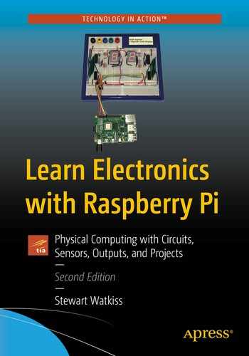
A micro-USB power breakout connector
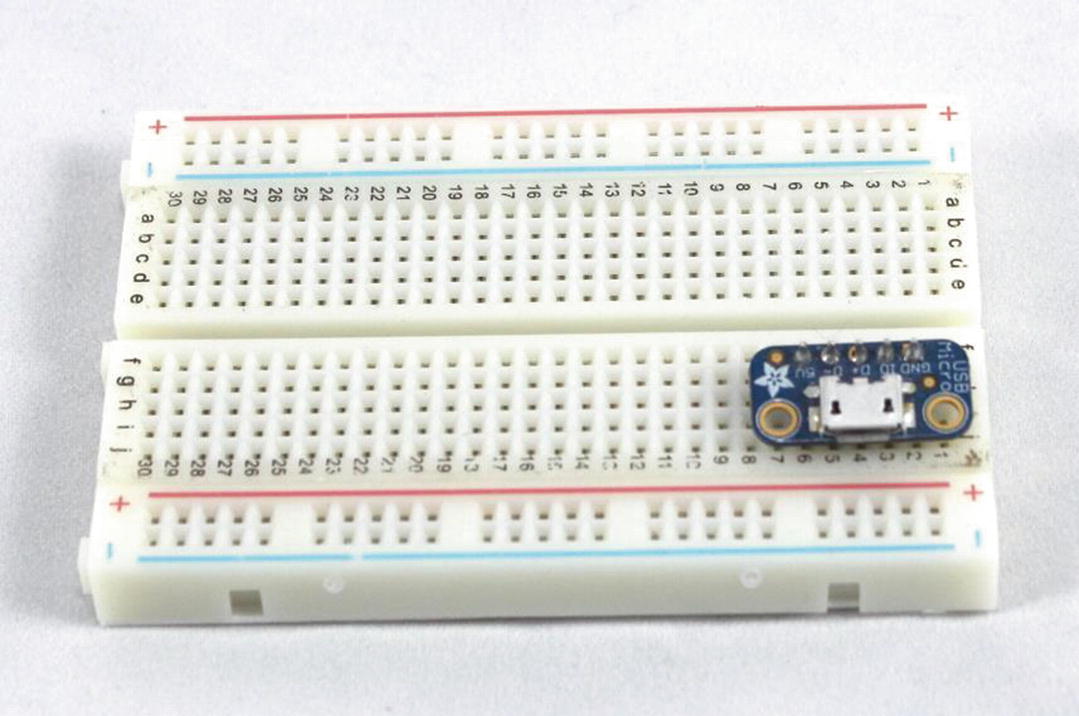
Micro-USB power supply
Other External Power Supplies
The USB power supplies are good if you have a 5V circuit with modest power requirements, but if you have a circuit that runs at a different voltage or needs more power than the USB power supply can provide, then you may need to look at a different power supply.

5V DC power adapter
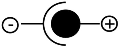
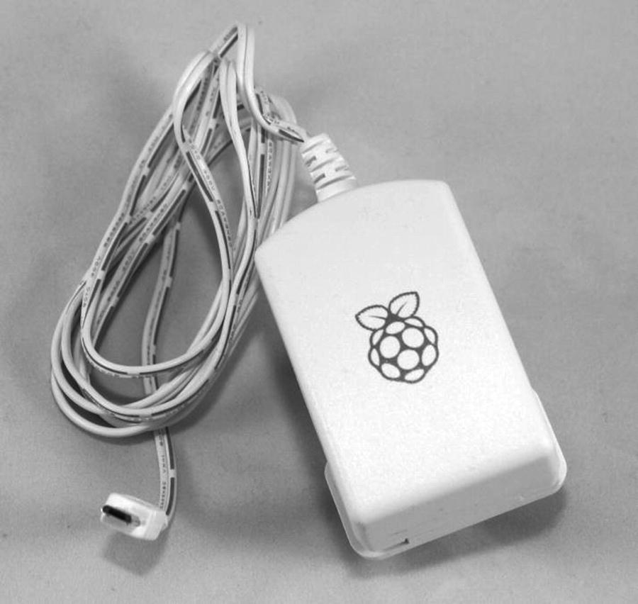
DC power adapter center positive indicator
You will also need to check that it is a DC supply, as they are also available as AC power supplies. When choosing a power supply, you will need to ensure that the voltage matches the required voltage and that it is capable of supplying at least as much current as is required. There is no harm in connecting a power supply with a higher current rating than is required as the power supply will only provide the current that the circuit requires, but you should not use a power supply with a higher voltage unless you know that is within the tolerance of circuit power supply requirements.
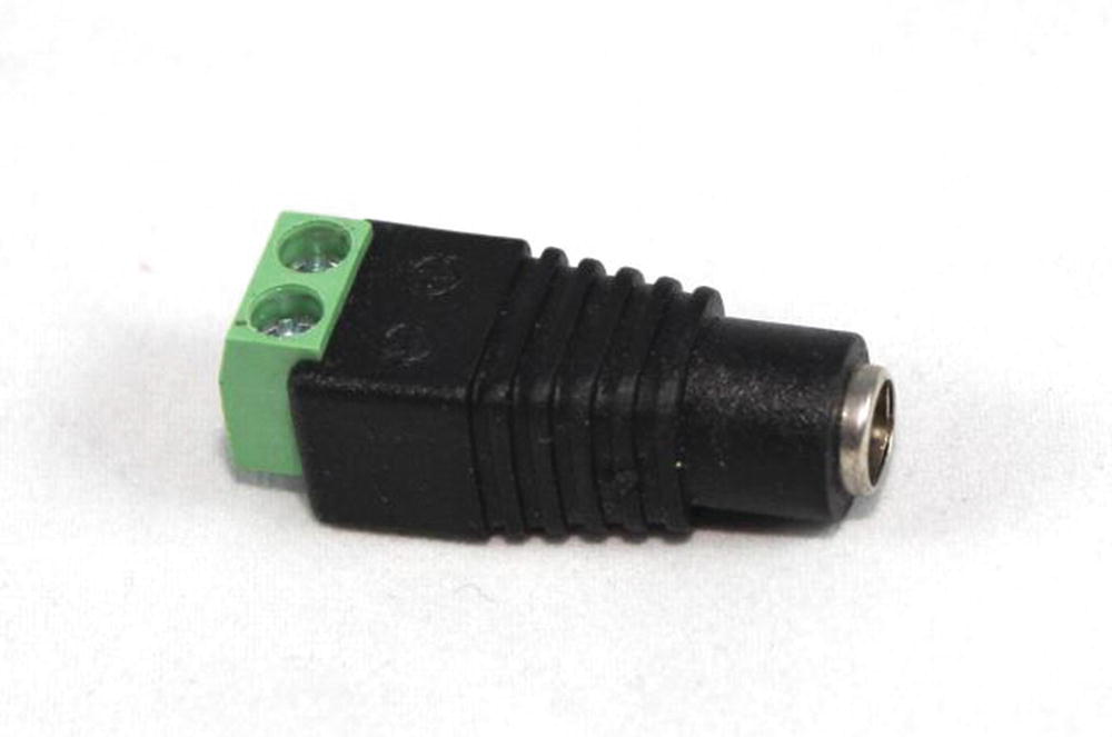
DC power adapter to screw terminal
As with the USB power supply, I recommend only using a power brick from a reputable supplier which meets the appropriate safety requirements. The output power supply from a power brick is normally low voltage and safe from electrocution (typically, 5–12V). A good quality power supply should also include short circuit overload protection, but you should not rely on this protection. Ensure that any circuits connected to these supplies do not draw more than the specified maximum current. As an extra precaution, you may want to include a fuse in your circuit, which I will explain later with the disco lights.
Mains Power Supply
It is possible to create your own low-voltage power supply by building a power supply circuit which connects directly to the main supply. I do not recommend doing so.
The mains power supply in your home is dangerous. If you come into contact with a live connection, then it can kill through electrocution, or overloading a supply, or wire could cause a fire. Unless you know what you are doing, you should only connect equipment to the mains power supply that already includes the appropriate insulation and protection (such as a wall wart or power brick).
Do not attempt to connect a homemade circuit direct to the mains electricity supply unless you know what you are doing – it is not worth the risk!
Batteries
Batteries can be used to power external circuits as well as the Raspberry Pi. Using a battery to power the Raspberry Pi itself will be covered in more details in Chapter 9. If it is just an external circuit that is being used and the power requirements are quite low, then batteries can be a good way of powering the circuit. An obvious advantage of batteries is that they are portable and so make it easier to move your project around but do make sure that the batteries have enough charge. If the circuit isn’t working or behaves differently to how you expect, then it could be because the batteries need replacing or recharging.
Brighter LEDs with a Transistor
In Chapter 3, there were some simple circuits which had LEDs and a resistor connected direct to the Raspberry Pi GPIO ports. This worked well with a standard LED which uses only a small current, but when swapping for larger or brighter LEDs, the current needed to light the LED is going to be higher. The maximum current that can be drawn from an individual Raspberry Pi GPIO ports is around 16mA. It will be even less if you have lots of devices connected.
The LED used here is a 10mm white LED. This is a bright LED that needs around 20mA to give off a good amount of light. This is more than the GPIO port can supply, so now it’s time to look at adding an electronic component that can increase the amount of current flowing (amplify the output). The component we will use is a transistor.
Transistor
The transistor is a semiconductor device, which means that under some conditions it allows current to flow (acts as though it’s a conductor) and in other conditions restricts the flow of current. It is this property that is so important in electronics and is the basis of most electronic circuits including computer processors.
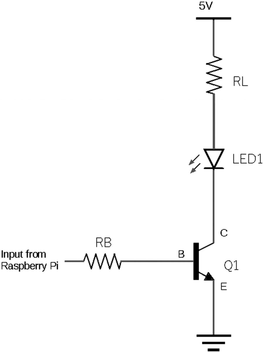
Circuit diagram for a transistor switch
You will notice that Figure 4-6 looks very different from the earlier circuits. Previously, we had a breadboard layout that showed the physical appearance of the components and wiring. This diagram shows the components as symbols rather than showing their physical appearance and shows the connecting wires as straight lines. This is known as a circuit diagram, or schematic. We will look at circuit diagrams in more details later in this chapter; for now, we will use the diagram to show how the components are connected.
The circuit shows two resistors labeled RB and RL, an LED labeled LED1, and a transistor labeled Q1. The connection from the Raspberry Pi GPIO port goes through a resistor RB and connects to the base of the transistor. When the GPIO port is switched on, the current flows from the GPIO port, through that resistor, and between the base and emitter of the transistor. The current flowing between the base and emitter switches the transistor on. This allows a larger current to flow through resistor RL, the LED, and then from the collector to the emitter of the transistor. The power supply used for the LED is from a 5V supply independent of the Raspberry Pi power supply, although the ground (0V) connections need to be connected together.
When using a transistor as a switch, the main characteristics of the transistor that need to be considered are the maximum current that it can switch which is referred to as the collector current (usually provided as IC) and the current gain of the transistor (referred to as hFE). We will also need to know about the voltage between the base and emitter to work out appropriate resistors, although that is not necessarily a characteristic that is used to decide on which transistor to use.
There are several different transistors that could be used for this circuit, but this covers two different types 2N2222 (in particular, P2N2222A1) and the BC548. These are both common transistors used for hobby projects. Only one of these is for calculating the appropriate resistors, but it will be possible to use either in the circuit depending upon which component you are able to buy. It will also provide a useful comparison of different transistors, which can be useful when designing your own circuits in future.
First, we need to check the suitability of these transistors. The maximum collector current for the 2N2222 is 600mA and the BC548 is 100mA. So, both are easily able to support the 20mA that is needed to control the bright LED.
The gain gives us details of how much more current can flow through the collector compared to the current through the base of the transistor. The actual value depends upon several factors and depends upon conditions at the time of manufacture; in the case of the 2N2222, it is about 75 and for the BC548 about 110. If we take the lowest of these, then it means that either transistor can switch at least 75 times the current through the collector compared to the base current. We shall use the 2N2222A for the rest of these calculations, but due to the similarity between these two transistors, it means that either transistor can be used in this circuit.
Calculating the Resistor Sizes
There are two resistors that you need to calculate the size of. The first is RL which protects both the LED and the transistor from having too much current through them. If too much current flowed through the LED, then not only would it be a waste of energy but could result in permanent damage.
To work out the resistor size, you need to know the voltage across the resistor. This will be the supply voltage minus the voltage dropped across both the LED and the transistor. The voltage drop across the LED is quoted as 3.3V. The voltage drop across the transistor varies depending upon the manufacture and the current flowing through it. It may be shown as a graph on the specification, but the value needed for this is when the transistor is in the saturation region, which can normally be taken from the general information. The voltage between the collector and the emitter is referred to as VCE(sat) on the transistor specification. The value is approximately 250mV.
Supply voltage 5V.
Voltage across the LED 3.3V.
Voltage across transistor 250mV.
Desired current through the LED is 20mA (0.02A).
The voltage across resistor RL is therefore 5V – 3.55V = 1.45V.
To calculate the resistor value, we use Ohm’s law, which is V / I:
1.45V / 0.02A = 72.5 ohms
There isn’t a resistor value of 72.5 ohms, so the nearest available resistor should be used. Using the next value up in the E12 series of resistors is 82 ohms (82Ω).
You can now work out the actual current using the selected resistor to check that the current is appropriate. Using Ohm’s law, the current is V / R. This works out as 1.45 / 82 = 18mA.
Alternatively, we could have used a 68Ω resistor, which would have worked out at 21mA. Again, this would have been OK as it would still have been within the 30mA maximum that the LED could use. This is a common occurrence within digital circuits where it is possible to use components whose values are near to the desired value.
To calculate the size for RB, you need to work out the current we want to flow into the base of the transistor and then choose an appropriate resistor. The current needed at the base is worked out using the collector current divided by the gain (hFE). We will use the hFE from the 2N2222A as this has the lowest gain.
This gives 20mA / 75 = 0.3mA.
You should then multiply the figure by 10 to ensure that we are well above the required base current. This isn’t a fixed rule but is something that is normally done to ensure that the transistor is fully in the saturation region where the power lost within the transistor will be at its minimum.
Multiplying by a factor of 10 gives us 3mA, which is the current needed at the base of the transistor.
Voltage from the GPIO pin 3.3V
Voltage drop across the transistor (VBE) 0.7V
Required current calculated above 3mA
The voltage across the resistor will be the GPIO high voltage less the voltage dropped in the transistor. 3.3V – 0.7V = 2.6V.
The transistor needs 3mA entering the base, so using Ohm’s law to calculate the resistor gives 2.6V / 0.003A = 866Ω. The nearest value is 1kΩ using the next higher value or 820Ω for the next lowest.
I have used 1kohm which gives around 2.6mA to the base of the transistor. Although our desired value is 3mA, this included a factor of 10, so we will still be well within the saturation region.
RL = 82kΩ
RB = 1kΩ
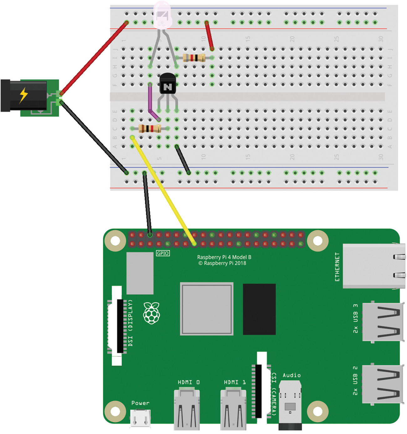
Breadboard layout for the bright LED circuit
You will see that I have used an external power connector in this circuit. You could use any of the other power supplies discussed earlier. This needs to be connected the correct way around with the red wire going to the top of the breadboard being from the positive supply of the power connector. Also note the orientation of the transistor which is placed with the flat part of the transistor facing forward in Figure 4-7. The pin layout for both the 2N2222 and the BC548 is the same, although that is not the case for all transistors. You will also need to ensure that the LED is the correct way around with the long lead connecting to the resistor (this was explained in Chapter 3 and shown in Figure 3-4).
This circuit uses the same GPIO port that we used in our first Scratch LED circuit, which is GPIO port 22 (physical pin 15). If you would like to try this as a brighter version of the LED circuit, then you can run the code from Chapter 3, Figure 3-7. The next step is to develop some code in Python, which is a more powerful programming language.
Introduction to Python
Python is a popular programming language that is used throughout education and industry. Python is a text-based language which involves writing the code that is run by the Python interpreter. The examples we use here will be run from the command line, but you will see how a simple GUI (graphical user interface) application can be used in Chapter 7.
I won’t be providing a full guide to Python in this book, but we will look at some of the basics to get you started. If you haven’t done any programming in Python before, then there are many books dedicated to teaching Python programming.
There are two versions of Python installed on the Raspberry Pi. The first is version 2.7 which is the last version of the old Python and Python 3 upward which is a newer version, but which is not fully compatible with the earlier version. I encourage using the new version as that is the future of Python and that’s what is used in this book.
The first thing to notice about Python is that it is a text-based programming language. If you have been used to a block-based programming language like Scratch, then this can be a big jump at first, but it shouldn’t take you long to get used to it. Once you’ve learned the basic rules, the additional flexibility will increase the scope of what you can achieve.

Launching Python Mu editor
When you launch the Mu editor for the first time, it will prompt you to select which mode to run in. For most of the code in this book, you should choose Python 3. You can change the mode using the Mode icon on the editor. The editor will then load an empty document which is untitled. It has a line starting with a “#” character which indicates that this is a comment. The comments are ignored when you run the program but can be very useful for other people to understand how the code works and can be useful as a reminder for yourself when revisiting the code at a future date. I strongly suggest you get into the habit of putting comments in your code.
The editor window can be used to write your code. You can then test the code by clicking the Run button. There’s also a useful button titled REPL. This stands for read-eval-print loop; it provides a way to run commands through the Python interpreter without having to save it into a program. This can be useful to test a short snippet of code or to understand what a certain function does, but for most programs, you will want to save your code in the text editor so that you can run it again without having to re-enter it.
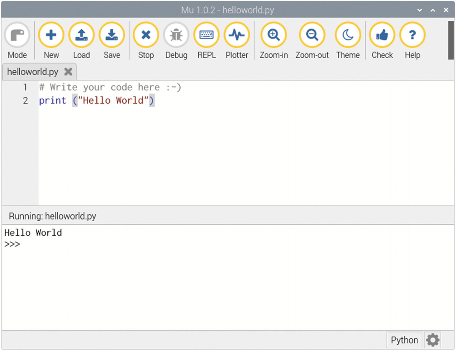
Mu editor running Hello World
If you haven’t saved the program first, then you will be prompted for a filename. Subsequently, the editor will auto-save whenever you press Run.
Commands are written in the text editor using a similar language to what you have already seen in Scratch. There are a few syntax rules that need to be followed.
The first is that indentation and white spaces are important. This is one of the most noticeable things in Python as very few other languages are as strict in enforcing rules about spaces. In most other languages, such as C and Java, any spaces or tabs at the beginning of a line are ignored. In Python, they are used to determine whether you are inside an if statement, loop, or function. Not only that, but in Python 3, it is fussy about whether they are tabs or spaces as well. By default, Mu will replace all tabs with four spaces which is a good way to deal with the spaces. Python will ignore any completely blank lines (that have only white space characters).
Another thing about Python and most other programming languages is that it is case-sensitive. This means that calling a variable MyVariable but then referring to it later as myvariable will not refer to the same variable and will likely cause the application to give an error message or even crash.
will add all three entries together even though they are split across multiple lines. It is very rare that I use this feature in the code I write, but it is useful in a book where there is a limited page width to fit the code in.
You will see some more elements of Python programming later in this book.
Getting Started with Python GPIO Zero
To control the GPIO ports involves some complex code that is specific to the Raspberry Pi. Fortunately, this has already been written for you and made easy to use thanks to the GPIO Zero Python module. There is a list of rules that are used to communicate with the GPIO Zero code, which are known as an application programming interface or API. We won’t go into the full details, but a summary of the API is included in the following.
The module needs to be loaded from within the Python program using from gpiozero import <name>, where <name> should be replaced with the name of the feature you would like to import (e.g., LED) or * to mean import everything in that module. You can then refer to the various interfaces by their name such as LED or Button. There is a list of supported devices given at https://gpiozero.readthedocs.io/en/stable/.
Simple program to flash an LED
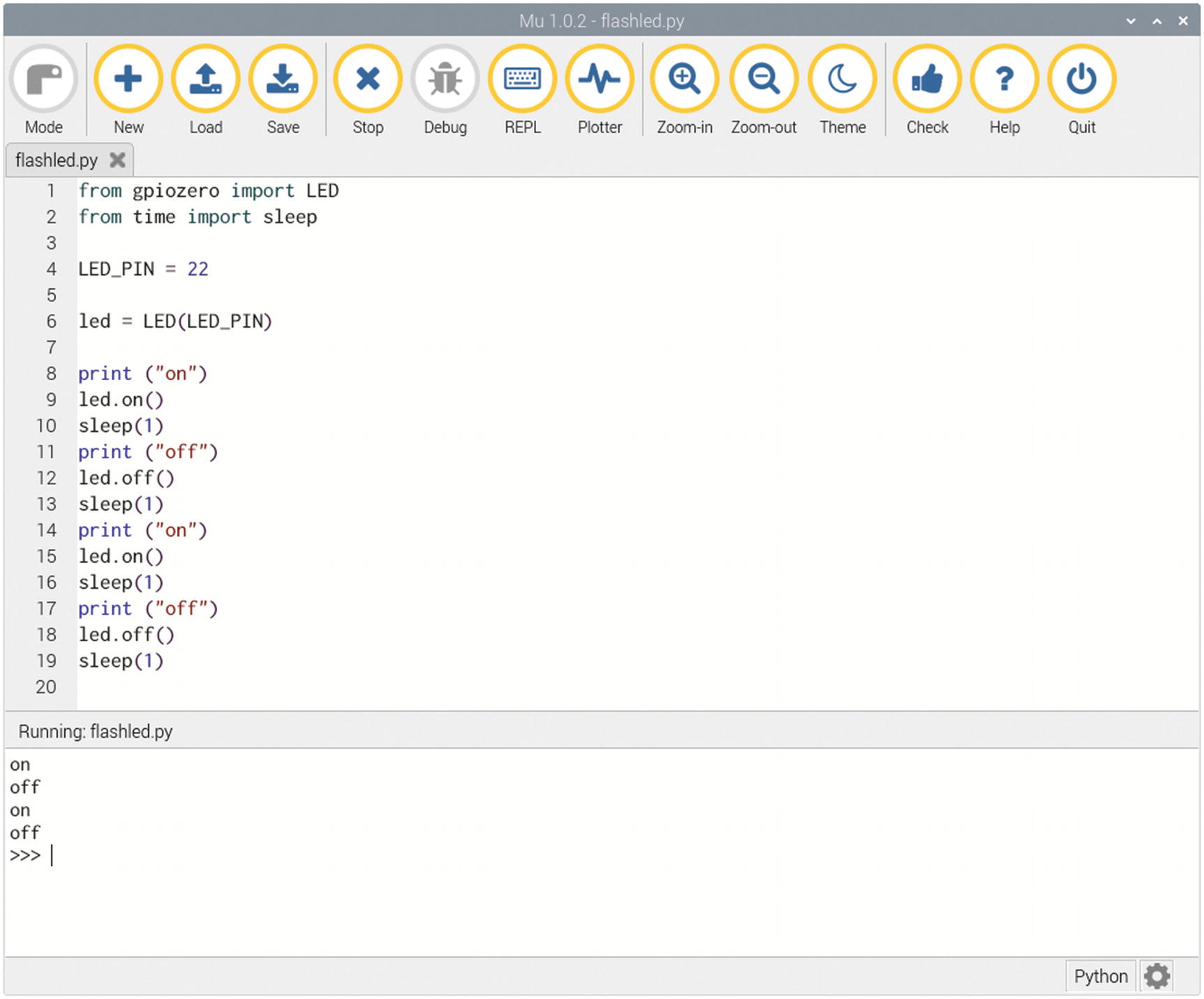
Running the GPIO Zero LED code
The source code is also available in the book source code available to download. The file is in the Chapter 4 folder called flashled.py.
In Figure 4-10, the code is shown in the editor with the output from running the program at the bottom of the editor. Obviously, the main output is in the form of the LED flashing on and off, but I have also included some print statements so that it shows the expected status on the screen. The LED should flash twice, coming on for one second and then off for one second each time. If the LED does not flash as expected, then check the wiring matches Figure 4-7 and check that the transistor and LED are correct the right way around.
The code starts by importing two modules. The first is gpiozero, and the second is the time module, which is used to add a delay between the instructions. When gpiozero is imported using “from” format whenever you want to refer to LED, then you can just call it LED.
The next entry creates a variable called LED_PIN and stores the value 22. This is to store the GPIO port we are using, so that instead of having to remember it is gpio 22, you can instead type LED_PIN. This is a constant as it will never change during the program; Python doesn’t support constants, but using uppercase for a variable name indicates to the programmer that it shouldn’t change. It’s usually a good idea to list any constants at the beginning of a program, so that if in future you change which port the circuit is connected to, then you only need to change the value in one place. Whenever you see LED_PIN through the code, it will be replaced by the value 22 when the program runs.
It then creates an instance of the LED object using LED from the gpiozero module. I have called it led (in lowercase), which is how it will be referred to when turning its output on and off. This will set the port, entered within the brackets, as an output port and allow us to change the state of the output.
The next block of code changes the status of the LED. First, there is a print statement which sends a message to the shell where the program is running. This is not necessary but can be helpful when testing as it tells you whether the LED should be on or off.
The lines led.on() and led.off() turn the output pin on and off as appropriate and sleep(1) tells the computer to sleep (do nothing with this particular program) for one second.
Using a While Loop
Program to flash an LED using a while loop
The text within the while loop is indented. This tells Python that those instructions are within the while loop. If they were not indented, then they would not be within the loop and so would not run as Python will never exit the loop. To stop the program from running, you need to be in the command shell and press Ctrl and c at the same time.
The source code is also in the source code for the book, with filename flashled2.py.
Circuit Diagram and Schematics
For most of the circuits so far, the diagram has shown the breadboard layout. This is a good way to see how to wire up the circuit but can be quite difficult to see how the circuit works. For example, in Figure 4-7, there is a transistor on the breadboard but without knowing which pin of the transistor is the base, collector, and emitter, it’s difficult to visualize how the transistor works within the circuit. It is also very difficult to show larger circuits using a breadboard layout as the wires crossing each other could end up looking like a bowl of spaghetti. Instead, the circuit needs to be shown on a diagram which shows how the components fit together without showing the actual physical positioning. The diagram that can provide that is called a circuit diagram or a schematic. In a circuit diagram, the components in the circuit will not look like the physical components, but instead be replaced with circuit symbols.
The circuit diagram shows the components as symbols connected with straight lines. These lines are generally replaced with wires or copper tracks on a PCB.
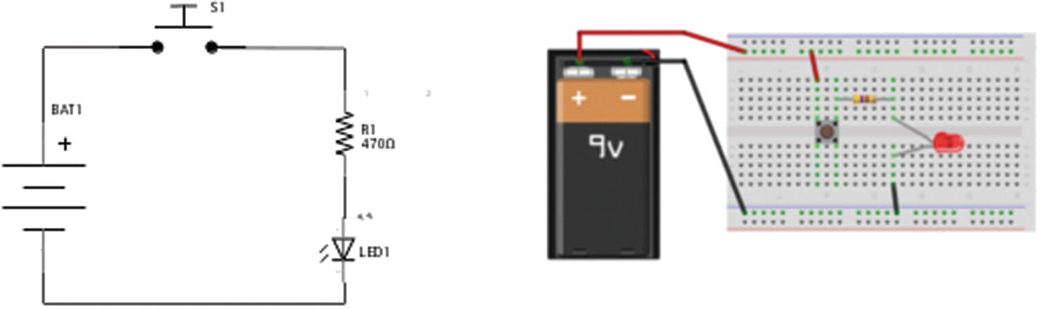
Simple LED circuit as circuit diagram and breadboard layout
As you can see, these look very different, although if you follow the lines around the circuits, you will see that the same components are used and that they are connected in the same order on both circuits.

The resistor circuit symbol using the US and international standards
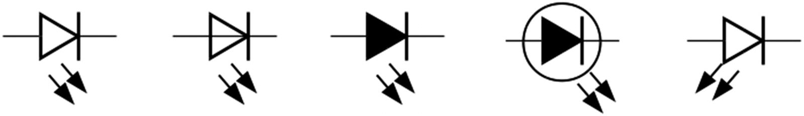
Different symbols for the LED
The variations shown in the LEDs are common differences that also appear with some other components. This includes shapes that may or may not be filled, or there may be a circle around the symbol.

Common circuit symbols
Each of the symbols is briefly explained as follows with more details of the actual component provided in Appendix B.
The resistor has already been used several times in the book to reduce the amount of current. The variable resistor adds a third connector which can be moved along the length of the resistor providing a different resistance value.
A diode only allows current to flow in one direction. The symbol shows the direction of current going from the positive end of the component (anode) on the left to the negative end (cathode), which is on the right. The LED (light-emitting diode) is a specific version of the diode that gives out light when current flows.
The switch symbol can be used for any type of switch, although sometimes different symbols are used for different types of switches. The push-button switch symbol is sometimes used for switches which are only closed when the button is being pressed and then open when released.
The NPN transistor is a semiconductor device already shown in Figure 4-6. There is another variation called the PNP transistor which relies on the current flowing out of the base rather than into the base. The base (B), collector (C), and emitter (E) are shown on the symbol but are not normally shown in a circuit diagram.
The MOSFET will be explained later in this chapter. The drain (D), gate (G), and source (S) are shown on the symbol, although these are not normally shown on a circuit diagram.
A battery symbol is shown. Many diagrams will just show this as a power supply by indicating the voltage rather than specifically showing it as a battery. There is a longer line for the positive terminal on the battery. The + symbol for the positive terminal is sometimes included and sometimes not. The positive terminal will normally be at the top of the diagram.
The ground symbol is used to indicate the ground 0V connection of a power supply. There may be multiple ground connections on a diagram. All the ground connections are connected which can reduce the number of lines on the diagram.
A capacitor is used to store electrical charge. They are available as non-polarized capacitors, which can be connected either way around, or polarized capacitors, which need to be connected the correct way around. It is important that polarized capacitors are connected the correct way around, as otherwise they can explode.
Finally, two different ways of showing an integrated circuit are shown. The first shows the integrated circuit as a rectangle with each of the pins as connection into the symbol; the model of the integrated circuit is shown in the center. Usually the pins are shown in numerical order, although sometimes they are rearranged to fit in with the circuit. The pin numbers are often shown, especially when they are not in numerical order. The pins’ function is shown inside the symbol using abbreviations. A common abbreviation shown in the diagram is EN, which indicates an enable pin which turns on the appropriate part of the circuit. For other abbreviations, you may need to look in the specification to find the meaning of the pins.
The other way for an integrated circuit to be shown is by its function. The non-inverting buffer and inverting buffer are shown by their function. In this case, the power supply connections to the integrated circuit are not shown but will still need to be physically connected. The circle at the end of the buffer indicates that it is inverting, which means that it will give a low output for a high input and a high output for a low input.
Other circuits and boards, including the Raspberry Pi, are shown in a similar way to the integrated circuits.
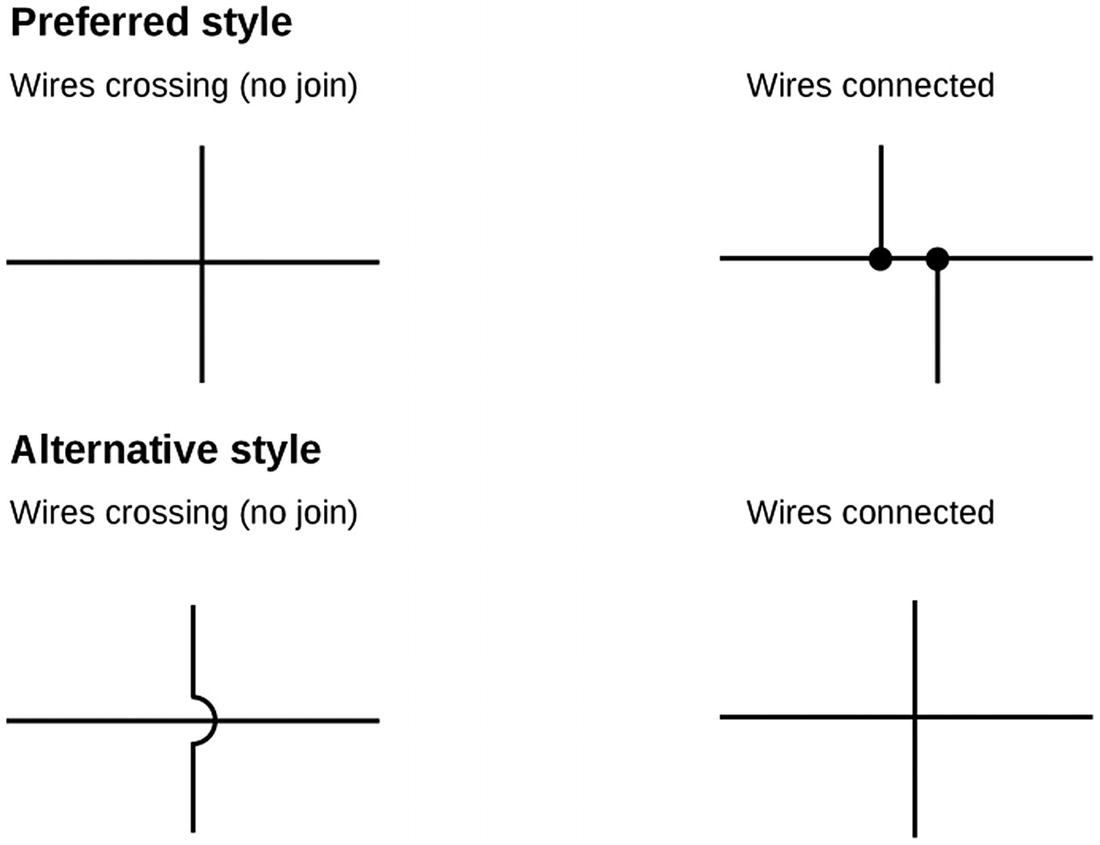
Circuit diagram representation of crossing and connecting wires
Note that the two different styles using the same straight crossed line mean the opposite. It is the presence of either the dots or the bridge that indicates which style is being used.
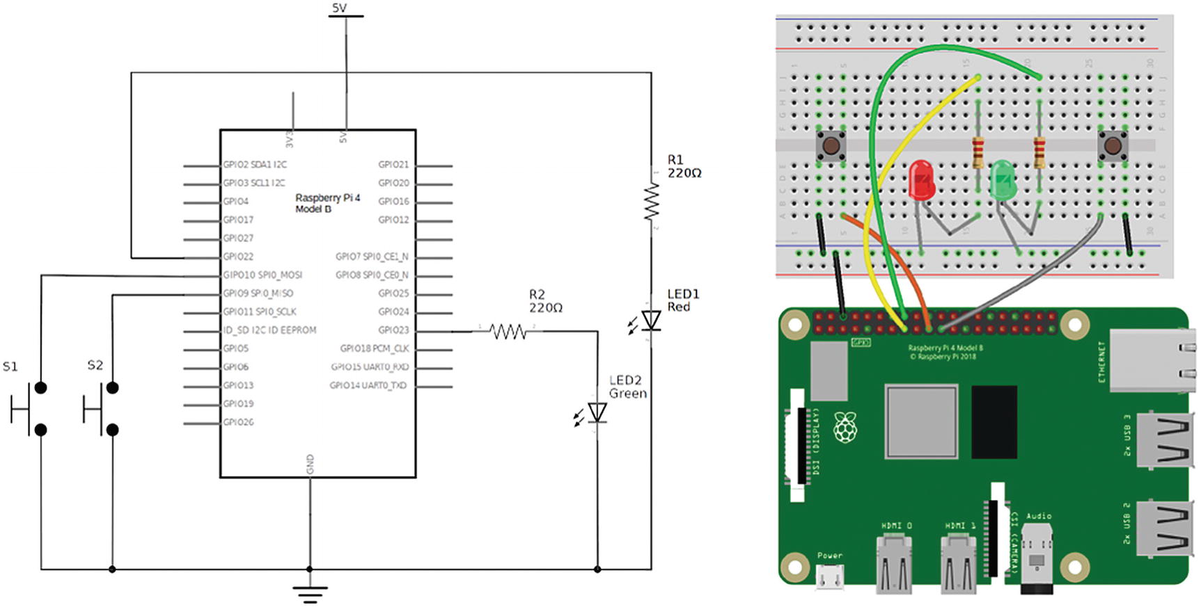
Circuit diagram for the Robot Soccer game
Brighter LEDs with Darlington Transistors
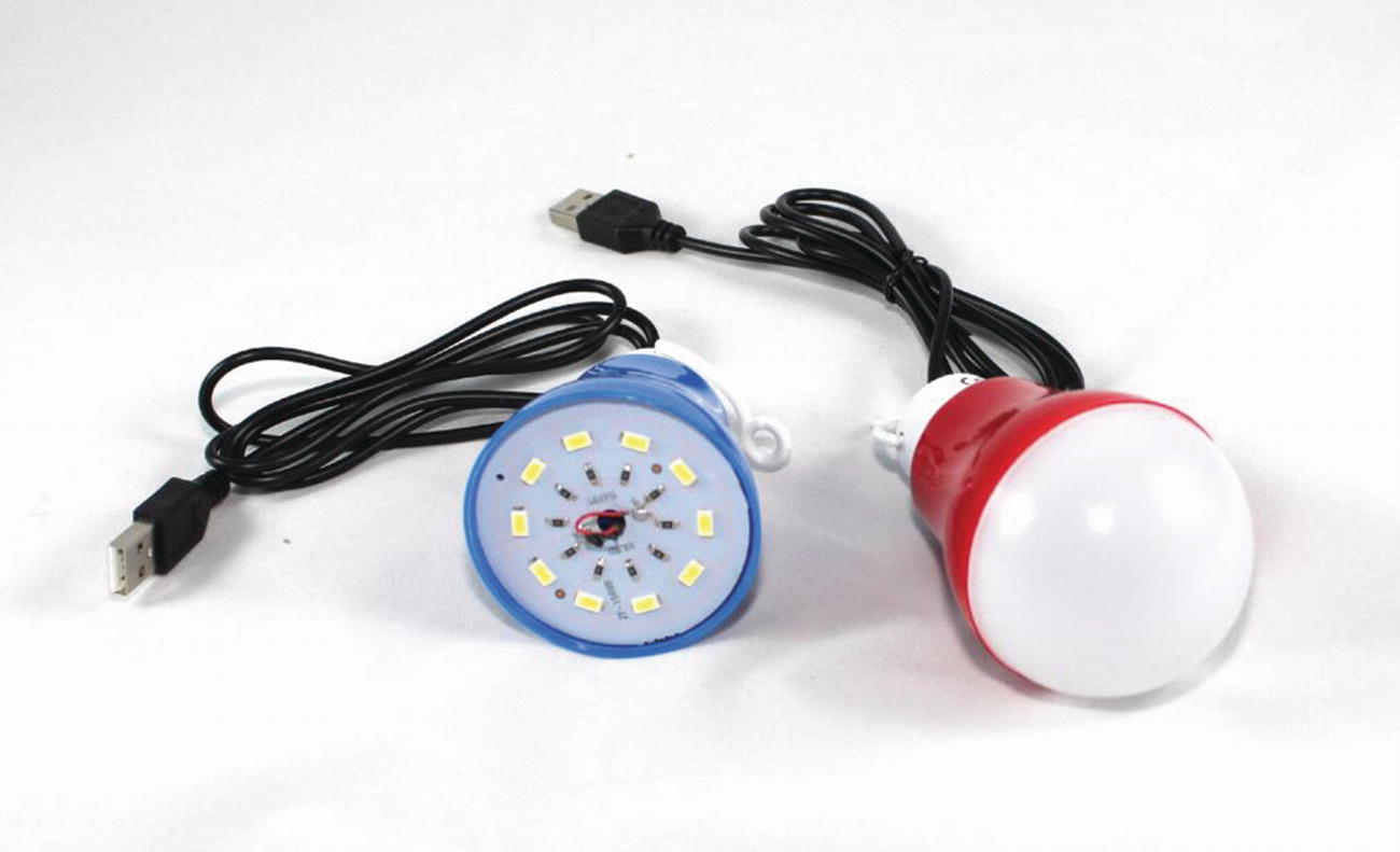
LED light with and without the top removed
The USB light was bought from a discount retail shop rather than a specialist electronics supplier, and as such, there is no technical information provided. Connecting to a 5V USB power supply, the light draws around 500mA, although when it does, the supply voltage also drops to around 4V.
Looking at the BC548, that is not able to switch 500mA and so could not be used, but what about the 2N2222? The 2N2222 transistor can supply the 500mA current we need, but you also need to take into consideration the amount of base current needed to switch the transistor into saturation.
In the previous LED example, it needed around approximately 3mA to switch the 20mA required for the bright LED, so to switch 200mA, you will need approximately 25 times that value which at 75mA is much more than the 16mA that the GPIO port can provide.
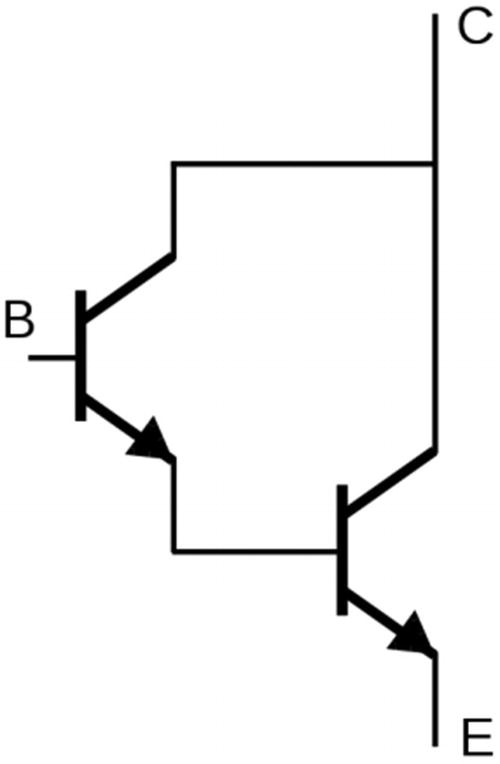
Darlington pair
VBE is 1.5V.
VCE(sat) is 1.5V.
hFE (gain) is 750.
IC (maximum collector current) is 4A.
These values can be used in the same way as a single transistor. Note that the voltage required at the base and the voltage dropped across the collector and emitter are both noticeably higher than a single transistor, but so is the gain. The maximum collector current is also much higher.
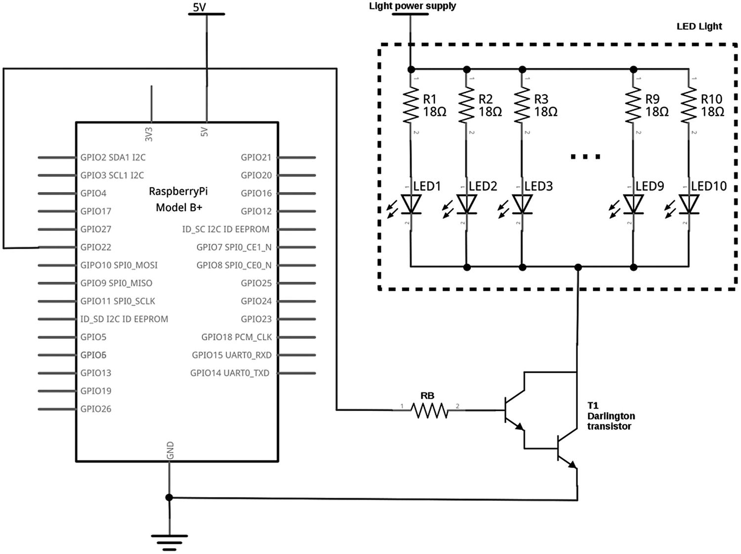
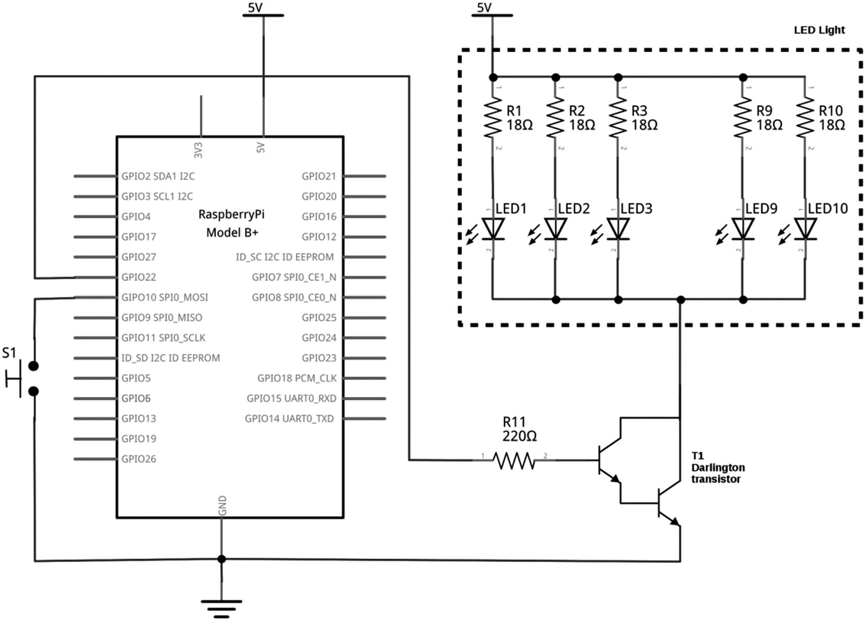
Darlington light circuit
For this circuit, I have shown the LEDs and resistors that are inside the light, using a dashed box. This is done to show which parts are within the USB light rather than in the circuit I created. Due to space, I have only shown five LEDs, but there are actually ten within the light.
There is a potential problem with this circuit. The resistors in the LED light will have calculated assuming a 5V power supply connected to the light. But assuming we stick with a 5V supply and then with 1.5V drop across the Darlington transistor, we will be running the light at 3.5V for the total light. You can perform some quick calculations to check this.
The resistors in the light are labeled 180, which indicates that these are 18Ω resistors (18 x 100). Assuming a 50mA current through each LED and associated resistor, this works out as 0.9V (18 x 0.05) dropped across the resistor. There is also some resistance in the USB lead of a little over 3Ω. While 3Ω does not sound like it will make much difference, the lead carries the full 500mA total current, which works out at about 1.5V dropped within the lead. After rounding the figures, the forward voltage of the LEDs is around 3A, which I verified using a multimeter.
Based on the 1.5V voltage dropped across the Darlington transistor, will there still be sufficient power to light the LEDs? If not, then what can we do about it?
It turns out that in practice this does still work and there is only a small drop in the brightness. When switched using the Darlington transistor, due to the voltage dropped across the transistor, the current flowing through the LEDs is less than when it is connected direct to the power supply. This means that the voltage dropped within the lead and resistors will be lower and there is still enough current flowing to light the LEDs. It appears that we can use the Darlington transistor. There is a risk that due to the tolerance of the components used, it may not work for every LED light.
When designing circuits for your own pleasure, you can often “get away” with working outside of the specified range. This is something you should be much more cautious of if designing a circuit for commercial purposes.
So how do we ensure that it will work?
You could remove the resistors all together and replace them with a direct link or a zero ohms resistor, which would help bring it closer to the original current as there would just be the resistance within the lead. This is generally a bad idea unless you are going to permanently attach the lights to our circuit. If we leave the USB connector on the end, then there is a risk that someone could plug it into a computer or other power supply, and without the resistors, it could attempt to draw too much current damaging either the USB light or the source of the power.
The safe solution is to increase the power supply to accommodate for the voltage dropped in the Darlington transistor. If you replace the 5V power supply with a 6.5V power supply (if one was available), then this would allow the full 5V for the USB light. A more common power supply is 7.5V, but then you’d need to add a further resistor to reduce that by the extra 1V, which would again be a waste of energy. As this works in practice using a 5V, I’ve just worked all the calculations based on 5V. To calculate the appropriate resistors, you can use the same calculations as for standard transistor switch circuit but substituting in the equivalent values for the Darlington transistor. As you already have the resistance for the LEDs, it is just RB that we need to calculate.
This gives 500mA / 750 = 0.7mA.
When a transistor is used as a switch (or in this case, the Darlington transistor), it is common to use a factor of 10 to ensure that the current is well above the required base current. This ensures that it is in the saturation region where the power lost within the transistor will be at its minimum.
3.3V – 1.5V = 1.8V dropped across the resistor.
R = V / I
0.8 / 0.007 = 257Ω
A suitable resistor value (using the E6 series) is therefore 220Ω.

BD681 Darlington transistor pin-out
This circuit uses the same GPIO port as we have used in the previous examples, so it will work with our existing code. Remember that GPIO port 22 is physically pin 15 and that the ground needs to be connected to an appropriate pin such as pin 6.
Such a bright light is more useful as a time delay light, which with an appropriate delay can be used as a time delay night-light, or a really bright egg timer. The light will turn on when a switch is pressed and then off again after a set delay, for that we need an input which we will add next.
Reading a Switch Input with Python GPIO Zero
Darlington light circuit with switch
Then create a button as button = Button(GPIO_Number). By default, GPIO Zero assumes that a Button should have the pull-up resistors enabled which is exactly what we want. If you don’t want the pull-up resistor, then pull_up=False should be added as a second parameter to the Button function.
There are a few different ways to detect whether the button is pressed or not. The first checks for the is_pressed state of the button. If the button is pressed down, then this gives a True value; if not, then it gives a value of False. This is useful if you have other things that you need to test for.
An alternative, which is the way I’ve coded the next program, is to use the wait_for_press() method . This pauses the execution of the code until the button has been pressed. It then turns on the LED and uses sleep() to wait for a set delay period. The LED is turned off again, and the while loop starts again. I’ve also added some comments (prefixed with a #) to explain what the constants are used for.
Simple program for an LED timer
This code is also available in the source code to accompany the book. The file is called ledtimer.py.
When run, this will wait until the button is pressed and then turn the LED on for the set period of time (30 seconds) and then turn it back off again. If the button is held down or pressed again, then it will turn the LED back on again for a further period. Press Ctrl-c to cancel if you would like to stop the program from running.
One of the disadvantages of the Darlington transistor is the voltage drop between the collector and emitter is high. This results in quite a bit of wasted energy in the transistor. The next example will cover an alternative that can be a more efficient way of switching bright lights.
Disco Lights with MOSFETs
Now to get even brighter! The LED light that was used in the last project was around 2.5 watts, this one uses 5W LEDs. Not only that, there are four of them with a total of 20 watts of power being controlled from the Raspberry Pi.
P = V x I
where P is the amount of power in watts, V is the voltage in volts, and I is the current in amps.
The LED light used previously was designed for a 5V supply and used 500mA (0.5A), so this gives 5 x 0.5 = 2.5W. This is the total power used by the light, which includes the power that is wasted in the resistors and the cable.
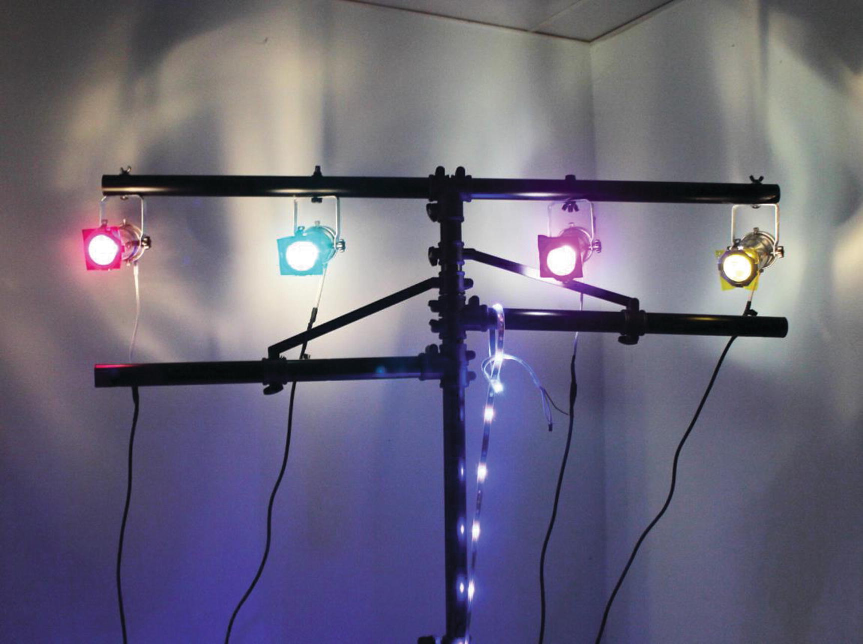
PAR 16 spotlights used as multi-colored disco lights
The PAR 16 spotlights are available as two different types. Some are designed for mains electrical voltage using GU10 light bulbs, and others are designed for low 12V operation using MR16 light bulbs. The following circuit is intended for the 12V light bulbs only.
The circuit used here is only suitable for low-voltage (12V) bulbs. Do not attempt to use this circuit to control bulbs that are designed to be connected directly to the mains electricity.

MR16 LED bulbs which work with 12V AC/DC

Power brick for the disco lights
One risk with using such a powerful power supply is what happens if there is a problem with the circuit. Most good quality power supplies should have overcurrent or short circuit protection, but it does still mean that you are able to provide 120W of power into a circuit before that kicks in. I therefore recommend adding your own fuse or protection into the circuit. This should be rated above the maximum current that you expect to draw, but less than the total power output of the power supply. I have used a polyfuse in my own setup, which is a self-resetting fuse. Effectively, the fuse will break the circuit when the current is exceeded but when left to cool will then reset and work again.
That has covered the lights, the bulbs, and a power supply, so the next thing is an electronic circuit. The first thing to look at is the amount of power that it needs to control. The LED packaging states 5W, but looking at the technical specification (which varies between manufacturers), the current draw is actually 625mA, which is 7.5W. This looks like the rating on the packaging is based on the amount of energy that is used to create the light, and the rest is lost as heat energy. This is much less energy wasted than an incandescent or halogen bulb, but it’s important to make sure that you look at the actual current rather than the marketing information on the front of the box.
You could use the same Darlington transistor circuit used previously. At 625mA, this is only a little more than the previous example which had a current of 500mA; however, as already explained, the Darlington transistor does have a relatively high voltage drop which results in a lot of wasted energy in the transistor. Not only is this wasting energy, but it may mean needing to add a heat sink to the transistor to dissipate the heat. Instead of using the Darlington transistor, a better option is to use a MOSFET which is a type of field-effect transistor (FET) .
A field-effect transistor is a type of transistor which is switched using electrical charge instead of the base current that is used in a bipolar transistor. A MOSFET is named based on its construction, which stands for a metal-oxide-semiconductor field-effect transistor. An advantage of the MOSFET over the bipolar transistor is that it uses a much lower current to switch it on, which is more efficient, particularly when used in integrated circuits. In our case, the voltage drop across the MOSFET is the most important factor. It has a much lower voltage drop across the device resulting in less power wasted. For the chosen MOSFET, the drop across the transistor is around 0.2V, which for a 12V supply is negligible and much less than the 1.5V from the Darlington transistor.
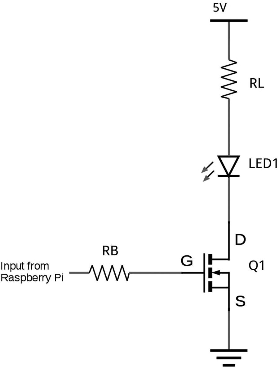
MOSFET switch circuit
You will see from the circuit diagram in Figure 4-25 that the terminals of the MOSFET are labeled G, D, and S. This refers to the Gate (like the base), Drain (like the collector), and Source (like the emitter). Whereas the bipolar transistor was turned on by a current flowing into the base, the MOSFET instead needs a positive voltage at the gate to turn it on and a low voltage at the gate to turn it off. The resistance between the Gate and Source is very high and so only a tiny current will flow. We do not need to worry about any gain within the MOSFET as setting the output high is enough to turn the MOSFET on.
In theory, the high internal resistance within the MOSFET would mean that you don’t need the resistor RB at all; however, the MOSFET behaves differently when it is first switched on, allowing a larger initial current to flow. You should therefore provide a suitable resistor to reduce this in-rush current.
This resistor just needs to be enough to protect the Raspberry Pi GPIO port, so assuming 3.3V output and 16mA maximum current, we have the resistance as 3.3 / 0.016 = 206Ω. So, I have used a 220Ω resistor.
As the LED unit is designed to be connected direct to a 12V supply, you don’t need to add a resistor for RL as that is already included within the LED. So, there are only two components needed for each LED, the switch and the resistor, which go between the GPIO port and the gate of the MOSFET.
GPIO 4 (pin 7)
GPIO 17 (pin 11)
GPIO 23 (pin 16)
GPIO 24 (pin 18)
Ground (pin 9)
The reason for using these ports is because I had an LED board that already used those ports, so I could use that board to test the code without needing to connect all my disco lights.
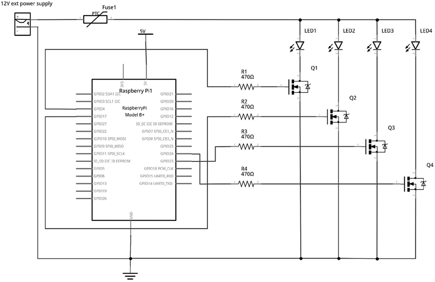
Disco light circuit
There are a few things to note about this diagram. Firstly, the device shown as Fuse1 is a self-resetting polyfuse used to protect against someone connecting an inappropriate bulb such as a halogen bulb. For simplicity, I have only shown the LEDs as a single LED and ignored their internal resistance. This is designed for use with 12V LEDs only, and connecting a standard LED in this configuration would most likely result in damage to the LED and possibly other components.
You may also note that the circuit symbol of the MOSFET is slightly different to the one used previously. This circuit symbol is the one used on some of the MOSFETs in Fritzing, which shows that there is an internal reverse biased diode within the MOSFET; this is still the same component, as that is an internal characteristic of the MOSFET. This is another example of how circuit symbols can vary slightly.
Light Sequence Using a Python List (Array)
Now that the circuit is complete, it’s time to create the code to make the lights flash in sequence. This code will create a light sequence that goes from left to right. To achieve this, we shall control the GPIO ports using a Python list. This is like an array used in other programming languages. Python does include support for arrays (which can be more efficient in certain circumstances), but a list is easier to use and more versatile.
A list is a data structure that can hold the value of multiple variables. So instead of having individual variables called light1, light2, light3, and light4, we can have a single list called lights which has four entries, one for each of the lights.
One thing to consider is that computers start counting from 0, and therefore, the index of the first element in the list will be at address 0. Scratch does things a little differently as it is aimed at a younger audience, so if you have used a list in Scratch, then you may have started at 1, but in Python and just about all other programming languages, you start at 0.
This creates a list of instances of the LED object using the appropriate entry from the LIGHTGPIO list for the port number.
This now allows you to add code that will flash each light in turn as a light chaser. This is shown in Listing 4-4.
Programming for light sequence
Based on the previous description, you should be able to follow the code up to the while loop. The while loop is another forever loop. The first step within the loop is to check to see if it has reached the end of the sequence. There are four lights, so 3 is the last entry in the list. If it is greater than 3, then it resets the sequence number to 0.
Next, there is a for loop which runs the next line four times. This works by using range (4) which expands to four entries 0, 1, 2, and 3. So it runs the loop the first time with x set to 0, and then with x set to 1, until it reaches the end of the fourth loop (number 3) when it exits from the for loop.
The line lights[x].off() turns the light off for each light. It then turns just the one light on using lights[x].on(). So if this is on sequence number 1, this would turn on the second light.
Finally, it increments the sequence number and waits for the set delay (1 second) before turning on the next light.
If you run the code, you should now see each light turn one in turn.
Switching AC Lights Using a Thyristor and a TRIAC
So far, all the lights we have been switching have been LEDs, which used a DC power supply. The bulbs used in the disco lights would normally be powered using an AC power supply, although I used a DC power supply as it’s easier to get a DC power brick suitable for a portable disco light controller.
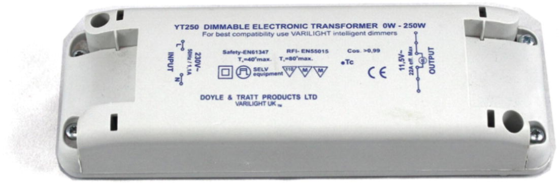
AC mains to 12V AC transformer
The first device that can be used for switching AC power supplies is the thyristor. This is a device that acts as a switch, which allows a current to pass in one direction only when it receives a positive signal to its gate terminal. Once triggered, it will normally continue to conduct as long as there is a forward current passing through it, even if the gate is subsequently taken low again. This has limited use in a DC circuit as it’s difficult to turn off, but in an AC circuit, the current will change direction each cycle and so will turn off whenever the current changes direction. By controlling when a thyristor switches on, they can be used as dimmers in lighting circuits.
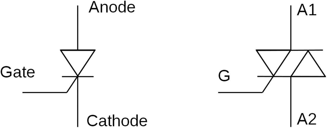
Thyristor and TRIAC circuit symbols
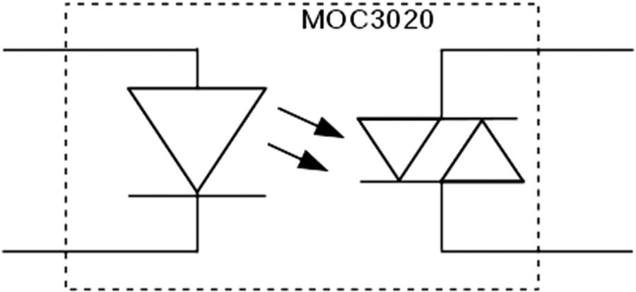
Circuit symbol for a TRIAC optoisolator
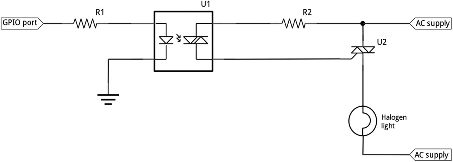
Circuit diagram of an AC TRIAC circuit
This circuit is intended for use with low-voltage 12V circuits. With appropriate components, this circuit could be used to switch mains electricity, but as with the warning earlier, this can be very dangerous, and you should only consider that if you really know what you are doing. In particular, if using mains voltage, then the circuit needs to be fully enclosed. The TRIAC itself can have live mains electricity connected to its outer body and if appropriate the heat sink.
More GPIO Zero
This chapter has looked at different external power supplies and how you can increase the small signal from the GPIO output to switch a much bigger load. This also provided a first introduction to the Python GPIO Zero module and how lists can be used to track multiple variables. From an electronics perspective, it covered the transistor, a two-stage transistor known as a Darlington transistor, and a MOSFET, which has been used to switch increasingly large loads. It also covered the TRIAC which would be used to control AC rather than DC circuits.
This chapter has also introduced the concept of circuit diagrams, which we will be using going forward instead of the breadboard layouts from the previous projects. You should now be able to decide on an appropriate position on the breadboard and wire up the circuit based on the diagram.
If you’ve followed along with the practical circuits, then the first LED should have been easy enough to buy, and the second one can use any suitable USB-powered light. The final project does use a more specialist light and power supply, but this can be replaced with the LED from one of the previous two projects (and resistor RL in the case of the first project). Alternatively, you could look at substituting the LEDs for other outputs such as a buzzer. You should avoid motors for the moment as anything using electrical motors needs some extra protection that will be covered in Chapter 6.
The disco lights will be left for a while but revisited in Chapter 7 which looks at creating more advanced software and Chapter 13 when I explain about the disco light printed circuit board that I created.
In the meantime, I suggest you look at creating code to create different light sequences. Can you make two of the lights come on during each cycle instead of just one? Think up some other sequences and write code that makes them light up the appropriate lights.