

4
CREATING LIGHT WITH LEDS
Lights, especially LEDs, are used all the time in electronics. Sometimes, they’re just simple indicators that show whether a device is on or not, but they can also be part of more complicated devices, like computer displays. In fact, some displays are actually made up of thousands of tiny LEDs.
In this chapter, you’ll learn how two of the most common basic components in electronics work: the resistor and the LED. I’ll show you how to kill an LED, but don’t worry: you’ll learn how to use resistors to keep LEDs alive, too. In this chapter’s projects, you’re also going to start using a new tool, called a breadboard, to connect circuits. Many projects in this book use breadboards, and you can also use them to build a lot of cool projects on your own.
MEET THE RESISTOR
Recall that resistance restricts current from flowing freely in a circuit. A resistor is a component that adds resistance to a circuit. The more resistance your circuit has, the less current will flow through it.
Resistor Color Codes
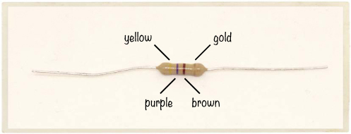
When you look at a resistor, you’ll notice that it has several colored bands. These colors tell you the value of the resistor. Resistance is measured in ohms, but when we write about it, we’ll use an omega symbol, Ω, for short. More ohms means more resistance.
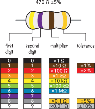
Most resistors have four color bands. From the left, the first band gives the first digit of the resistance value. In this example, the first band is yellow, so the first digit is 4. The second digit is given by the second band, which is purple for 7. Together, this gives us the base value of 47. Next we multiply 47 by the value of the third band—the multiplier. In this example, the brown band stands for 10 Ω, so we multiply 47 by 10:
47 × 10 Ω = 470 Ω
NOTE
If a resistor has five bands instead of four, then the first three bands are digits, and the fourth is the multiplier.
But the actual resistance of a resistor usually won’t match the value written on it! That sounds a bit crazy, right? It’s hard for manufacturers to create resistors with a very exact resistance value, so instead, they make sure the resistors are somewhere around that value and tell you how far off the real value could be.
This is where tolerance comes in. Our example resistor is labeled 470 Ω with a tolerance of 5 percent. This means that the resistor’s real resistance could be any value 5 percent higher or 5 percent lower than 470 Ω. Because 5 percent of 470 is around 24, the real resistance could be anywhere between 446 Ω and 494 Ω.
Usually, the three bands that tell you the resistance value are grouped together, and the band that tells you the tolerance is spaced a bit farther away. But sometimes the bands are so close that it’s hard to see which three bands give the resistance. Fortunately, the fourth band is typically gold or silver, so if you see a gold or silver band, it’s safe to assume this is the tolerance band.
What Are Resistors Made Of?
To create a resistor, you could just use a really long piece of standard wire. Wires have a bit of resistance, and the longer your wire is, the more resistance you’ll get. But using miles of wire to reduce current isn’t very efficient. It’s better to use a material that has more resistance, such as carbon. Often the resistors that you buy in stores are made of carbon wrapped inside an insulating material.
Resistors Control Current and Voltage
At first, you might find the resistor a bit boring. If you connect one to a battery, you probably won’t see anything happen; the resistor might just get warm, and you might wonder what the big deal is. On the other hand, if you use a resistor with a very low resistance value, such as 10 Ω, then it could get really hot—hot enough to give you a burn—and the battery might die pretty quickly.
WARNING
Connecting a low-value resistor directly between positive and negative points can be dangerous on some types of batteries. Some batteries are strong enough to make your resistor burst into flames. Be careful!
But the cool thing about resistors is that you can use them to change the voltages and currents in your circuit! That means that you get to be the master of your circuit and decide how it should behave.
INTRODUCING OHM’S LAW
The key to controlling the current and voltage in your circuit is a formula called Ohm’s law. Ohm’s law relates resistance, voltage, and current as follows:
V = I × R
Here’s what those letters mean:
V Voltage, measured in volts (V)
I Current, measured in amps (A)
R Resistance, measured in ohms (Ω)
Given these definitions, in English, Ohm’s law reads, “Voltage equals current multiplied by resistance.” You can also write the Ohm’s law formula in the two following forms:
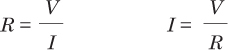
Let’s put Ohm’s law to work. Imagine you have a resistor and a 9 V battery, and you want 0.05 A of current to flow in the resistor. How much resistance do you need in the resistor to get the right amount of current flowing? Use Ohm’s law to find out:
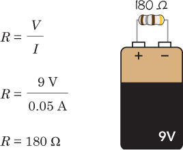
After dividing the voltage by the current, you’ll find that to get 0.05 A of current flowing in the resistor, you need a 180 Ω resistor.
PROJECT #7: LET’S DESTROY AN LED!
Almost all electronics have some LEDs, which I introduced in Chapter 3. Where there are LEDs, there are also resistors. Look around a house, and there’s a big chance you’ll see a few. For example, check a computer, a washing machine, a television, or a Wi-Fi router. Do you see some blinking lights when you push buttons? Those are very likely LEDs in series with resistors.
In “Project #6: Turn On a Light with Lemon Power” on page 58, you just connected an LED to your homemade lemon battery, and that was it. In most circuits, however, you need to take a bit more care to make sure you don’t break your LED. If too much current flows through an LED, it becomes really hot and burns out. The lemon battery was too weak to provide enough current to break the LED.
Of course, I could tell you all this forever, but trying things in real life is the best way to learn! I had to break a few LEDs myself before I accepted that I couldn’t connect them directly to a battery without a resistor, and I want you to see what that’s like, too. That’s why in this project, you’re going to destroy an LED!
Shopping List
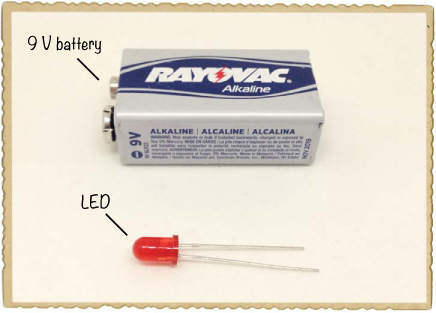
![]() A standard LED (Jameco #333973, Bitsbox #OP002).
A standard LED (Jameco #333973, Bitsbox #OP002).
![]() A standard 9 V battery to power the circuit.
A standard 9 V battery to power the circuit.
Step 1: Identify Which LED Leg Is Which
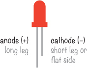
Look at your LED closely, and you should see that one leg is longer than the other. LEDs are polarized, which means that current flows through them only if you connect them a certain way in your circuit. The longer leg is called the anode; it’s the leg that you connect to the positive side of the battery. The shorter leg is called the cathode, and you connect it to the negative side of the battery.
On some LEDs, the legs are the same length. In that case, find the flat side on the bottom of the LED itself. The leg on the flat side is the cathode.
Step 2: Break That LED!
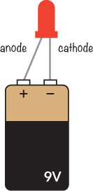
To avoid burning your fingers, hold your LED by one of the legs. Then, place the 9 V battery on the table and touch the legs of the LED directly to the battery terminals.
The LED should glow brightly for a short moment, become hot, and then go dark. Parts of it may actually turn black. Congratulations: You just broke your first LED!
NOTE
Some LEDs stop working after a second when connected directly to a battery. Others may give a bit of light for a few seconds.
Step 3: What If Nothing Happens to the LED?
If nothing happens, there are three likely causes:
![]() You connected the LED backward.
You connected the LED backward.
![]() Your LED is already broken.
Your LED is already broken.
![]() Your battery is dead.
Your battery is dead.
First, try connecting your LED to the battery the other way around. If you’re sure it’s connected the right way, then either your LED is already broken or your battery is dead. Try replacing the battery first; if that doesn’t work, replace the LED. Now, you should be able to break your LED.
HOW TO USE AN LED CORRECTLY
Even though it’s pretty fun to destroy LEDs, it’s better to know how to avoid destroying an LED. Your LED burned because it had too much current running through it, but you can prevent that with your trusted friend the resistor. Resistors resist the flow of current, and if you choose the right resistance value, they’ll resist the current enough to get just the right amount of current for your LED.
Protecting Your LED with a Resistor
An LED in a circuit should always have a resistor in series with it. Of course, resistors come in many different values, and to figure out the right one for your circuit, you need to do a little math.
Most standard LEDs need a voltage of about 2 V and a current of about 20 mA, or 0.02 A, to light up. These two values, together with the voltage of your battery, are all you need to figure out the correct resistance. Just put these two values into the following formula:
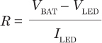
If this formula looks familiar, that’s because it’s actually just another version of Ohm’s law. The two Vs and the I are still voltage and current, but VBAT is the battery voltage, VLED is the voltage your LED needs to light up (often 2 V), and ILED is the current your LED needs (often 20 mA). You’d read this formula as “To find the resistance, subtract the LED voltage from the battery voltage and divide the result by the LED current.”
Calculating the Resistance You Need
Imagine you have a 9 V battery, a resistor, and a standard LED. What resistance value should the resistor be? Using the formula from the previous section, you should get:
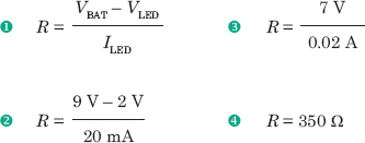
That means you need a resistor of 350 Ω to get the right amount of current flowing through the circuit.
PROJECT #8: POWERING AN LED
Now let’s power a standard LED with a protective resistor so the LED doesn’t burn out. We just calculated that to power an LED with a 9 V battery, you need a resistor of 350 Ω.
But as I explained in “Resistor Color Codes” on page 70, standard resistor values aren’t always exactly the resistance you need. If you buy a 350 Ω resistor, it isn’t necessarily 350 Ω, but maybe 370 Ω. And not all resistance values are even available. For a resistor in an LED circuit, having the exact value isn’t important. That’s fortunate because you won’t find any 350 Ω resistors in standard resistor packs. Instead, you can use a 330 Ω resistor, which is a standard value that’s easier to find.
Shopping List
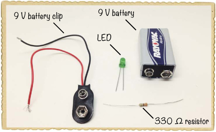
![]() A standard 9 V battery to power the circuit.
A standard 9 V battery to power the circuit.
![]() A 9 V battery clip (Jameco #11280, Bitsbox #BAT033) to connect the battery to the circuit.
A 9 V battery clip (Jameco #11280, Bitsbox #BAT033) to connect the battery to the circuit.
![]() A standard LED (Jameco #333973, Bitsbox #OP002)
A standard LED (Jameco #333973, Bitsbox #OP002)
![]() A 330 Ω resistor (Jameco #661386, Bitsbox #CR25330R for just this value or Jameco #2217511, Bitsbox #K017 for a variety pack) for limiting the current to the LED.
A 330 Ω resistor (Jameco #661386, Bitsbox #CR25330R for just this value or Jameco #2217511, Bitsbox #K017 for a variety pack) for limiting the current to the LED.
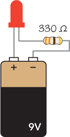
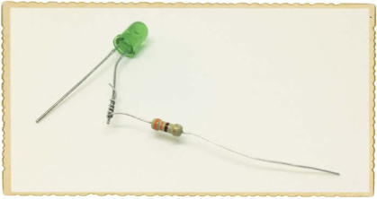
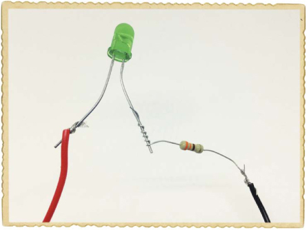
Step 1: Twist the Resistor and LED
First, connect the short leg, or the cathode, of the LED to one side of the resistor. It doesn’t matter which side of the resistor you connect; just twist the resistor leg around the LED leg.
Step 2: Wire the Battery Clip
Twist the battery clip’s red wire onto the long leg of the LED. Then twist the black wire to the unconnected side of the resistor.
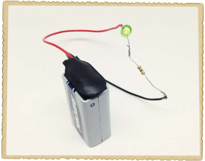
Step 3: Let There Be Light!
Now, plug your battery into the clip, and your LED should glow!
Step 4: What If the LED Doesn’t Work?
If your LED doesn’t turn on, first disconnect the battery and make sure you’ve connected the components exactly as I described in Steps 1 through 3. Having someone else review your wiring can be helpful, too; ask a parent, sibling, or friend to look it over.
If your connections look right and the LED is still dark, then double-check the LED’s orientation; just about anyone who’s ever built an electronics project has connected an LED backward at least once. The long leg is the anode, and in this project, it should connect to the positive side of the battery.
BUILDING CIRCUITS ON A BREADBOARD
Up to now, you’ve connected circuits with tape or by twisting component legs together, but this isn’t very practical when a circuit has more than a few components. Fortunately, a breadboard can make connecting components easier. Breadboards have holes that you can stick component leads into to create circuits. When you’re done, you can just unplug all the components and reuse them in different projects!
How to Connect Components and Wires
Inside a breadboard, metal plates connect the holes you see on the outside in a certain pattern. Let’s look at a breadboard with four connection areas—two supply areas and two component areas.
In the supply areas on both sides, all the holes in each column are connected. You’ll typically plug the positive side of your circuit’s power supply—like the batteries you’ve used so far—into the red columns, and you’ll typically plug the negative side of the power supply into the blue columns. Throughout this book, I’ll refer to the supply column marked with a red line as the positive supply column, and I’ll refer to the supply column marked with a blue line as the negative supply column.
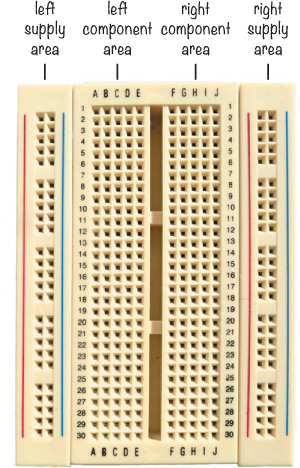
In the component areas, all the holes in each row are connected, and the columns are not connected. The left and right component areas are separated so that there’s no connection between them. For example, holes A, B, C, D, and E in row 1 are connected, and holes F, G, H, I, and J in row 1 are connected, but holes E and F in row 1 are not connected.
To plug a component into a breadboard, simply push it into the hole where you want the connection. For example, if you wanted to connect one side of a resistor to the positive side of an LED, you’d just insert both the leg from the resistor and the leg from the LED into two holes on the same row in the left or right component area. If you have two component legs or wires that shouldn’t connect, just make sure they are either on different rows in the component area or on opposite sides of the component area.
Wires to Use on a Breadboard
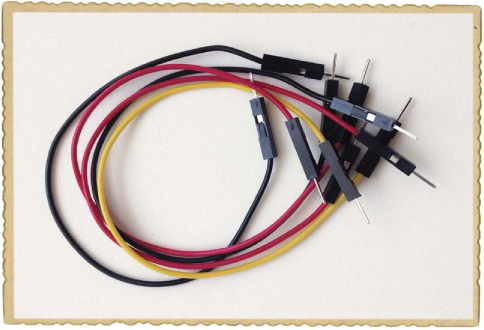
Eventually, you want to connect one row on your breadboard with a different row. You can use a wire to make that connection, but not all wires work well on a breadboard. The wire has to be stiff enough that you can push it into the hole without it bending, and it has to be thick enough to fit all the way inside the breadboard hole without falling out. Single-strand wires are the best wires for building circuits on a breadboard because they have one solid core inside, instead of many tiny wires wrapped together. The thickness of wire you need depends on your breadboard, but wires with 0.016- to 0.028-inch diameters should work. Wire thickness is often given in American wire gauge (AWG), and I recommend using wire that is 21 to 26 AWG. You can buy wires that are cut and stripped for simple use with breadboards, or you can cut and strip your own wires using a wire cutter.
Another option is to use breadboard jumper wires. These wires have stiff ends that are very easy to connect to a breadboard. If you plan to connect a lot of circuits on a breadboard (you should!), keep a bunch of breadboard jumper wires on hand to make your life easier.
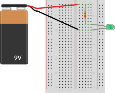
PROJECT #9: YOUR FIRST BREADBOARD CIRCUIT
Let’s connect a simple circuit on a breadboard! Just as in “Project #8: Powering an LED” on page 78, this circuit lights up an LED, but this time we’ll build the circuit on a breadboard. In this project, we’re not going to use the supply rails on the side because the circuit is so simple that it makes more sense just to connect it all on the component area.
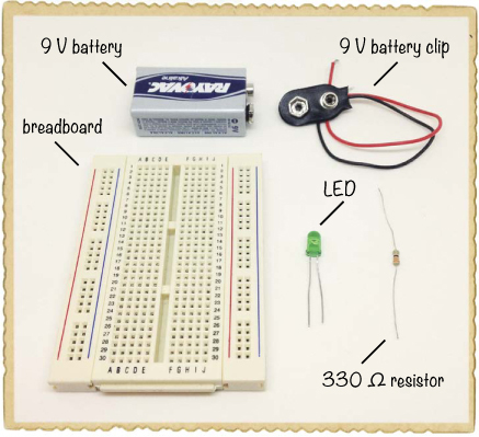
Shopping List
![]() A breadboard (Jameco #20601, Bitsbox #CN329) with at least 30 rows.
A breadboard (Jameco #20601, Bitsbox #CN329) with at least 30 rows.
![]() A standard 9 V battery to power the circuit.
A standard 9 V battery to power the circuit.
![]() A 9 V battery clip (Jameco #11280, Bitsbox #BAT033) to connect the battery to the circuit.
A 9 V battery clip (Jameco #11280, Bitsbox #BAT033) to connect the battery to the circuit.
![]() A standard LED (Jameco #34761, Bitsbox #OP003).
A standard LED (Jameco #34761, Bitsbox #OP003).
![]() A 330 Ω resistor (Jameco #661386, Bitsbox #CR25330R for just this value or Jameco #2217511, Bitsbox #K017 for a variety pack) for limiting the current to the LED.
A 330 Ω resistor (Jameco #661386, Bitsbox #CR25330R for just this value or Jameco #2217511, Bitsbox #K017 for a variety pack) for limiting the current to the LED.
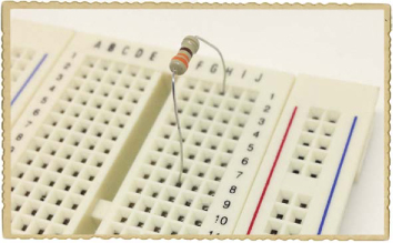
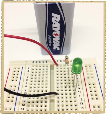
Step 1: Place the Resistor
First, place one leg of the resistor in row 1 and the other in row 8.
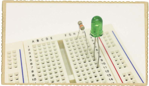
Step 2: Place the LED
Remember, LEDs are polarized, and they must be connected the right way to work. Connect the long leg of the LED to row 8, where the resistor leg is connected. Because the resistor and LED legs are on the same row, they’re now connected. Connect the other leg of the LED to row 10.
Step 3: Place the Battery Clip
Now, connect the battery to the LED and resistor. Connect the battery clip with the red wire at row 1 and the black wire at row 10. Plug your battery into the clip, and your LED should light up!
Step 4: What If the LED Doesn’t Work?
If your LED doesn’t glow, first disconnect the battery. You should always disconnect the battery when making changes to your circuit. Then, check whether the short leg of the LED is connected to the negative side of the battery.
If your LED is still not working once it’s oriented correctly, check that your components are connected exactly as described in Steps 1 through 3. Are the long leg of the LED and one of your resistor’s legs in row 8? Is the positive battery lead in the same row as the other resistor leg? Is the negative battery lead in row 10 with the short LED leg? Ask someone else to have a look at your circuit, too; maybe they can help you find the problem.