

5
BLINKING A LIGHT FOR THE FIRST TIME
When I was a kid, one of my very first electronics projects was making a light blink. It was amazing to see the circuit work for the first time, and now I want to share that experience with you. In this chapter, you’ll learn how the capacitor and the relay work. These are two common and very interesting electronics components, and I’ll show you how to have some fun with them. At the end, you’ll build your very own blinking light!
MEET THE CAPACITOR
The capacitor is like a rechargeable battery; you can charge a capacitor and use its energy to power something. But a battery can hold much more energy than a capacitor. A battery can power an LED for days without recharging, while most capacitors can power one for only a few seconds at most.

Capacitors are often used to introduce time delays in a circuit. For example, because a capacitor stores energy, it could be used to keep an LED on for a bit more time, even after the power is shut off. This little trick can be used with other components, too, to create interesting results.
How Capacitors Work
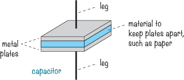
On the inside, capacitors are very simple devices. They’re made of two metal plates placed very close together, with a material such as paper in between. To save space, the metal plates and the material between them are folded or rolled into a compact package.
When you connect a battery to the two sides of a capacitor, a current flows as the battery tries to push electrons through the capacitor. But electrons can’t flow across the gap between the plates, so instead, electrons build up on one plate and leave the other plate. Eventually, one plate can’t hold anymore electrons, and the current stops flowing; at that point, we say that the capacitor is fully charged.
But just like the electrons in a battery, the electrons in the capacitor don’t like being crowded together on the one plate. They want to go over to the side with fewer electrons. This means you have stored potential energy in your capacitor. If you disconnect the battery and connect, for example, a resistor between both sides of the capacitor, the stored electrons on one plate will start flowing the other way around, through the resistor, in order to reach the plate with few electrons.
Polarized and Nonpolarized Capacitors
Capacitors can be either polarized or nonpolarized. Like an LED, a polarized capacitor has a positive and a negative leg, and its positive leg must always face the positive terminal of the battery. The black capacitor shown in the photo is polarized, and its negative leg is marked with a stripe and minus signs down the side. The yellow capacitor isn’t polarized, so it doesn’t matter which leg goes where.
WARNING
Take care when you use polarized capacitors for the projects in this book and in your own projects. You must connect them the correct way to prevent them from being damaged.
In all circuits that call for a capacitor, you can use a nonpolarized capacitor as long as you can find one with the right capacitance. Capacitance is measured in farads (F), and the more capacitance a capacitor has, the more energy it can store. Nonpolarized capacitors with large capacitances aren’t made because they’d have to be physically very large. Polarized capacitors are able to hold more energy in a smaller space, but they have the disadvantage of needing to be connected the correct way around.
When building circuits with high capacitance values, you’ll be using polarized capacitors. Always make sure the positive leg of any polarized capacitor is connected closest to the positive side of the battery.
Capacitor Values
The capacitors you’ll use in this book will have capacitances in the μF (microfarad), nF (nanofarad), or pF (picofarad) range. Capacitances tend to be very small, and they’re often written with the micro, nano, and pico prefixes, which are defined as follows:
![]() μ (micro) means millionth, so 1,000,000 μF = 1F
μ (micro) means millionth, so 1,000,000 μF = 1F
![]() n (nano) means billionth, so 1,000,000,000 nF = 1F
n (nano) means billionth, so 1,000,000,000 nF = 1F
![]() p (pico) means trillionth, so 1,000,000,000,000 pF = 1F
p (pico) means trillionth, so 1,000,000,000,000 pF = 1F
Polarized capacitors are big enough to have their values written on them. Nonpolarized capacitors, on the other hand, are a bit trickier. They’re usually really small, so they tend to have cryptic codes like 104 or 202. I always forget what they mean, so when I need to figure out what a certain code means, I just look it up in a table. You can find a table of common codes in “Capacitor Codes” on page 283.
But like most things, capacitors are much more interesting to play with than to read about. Build the next project, and you’ll see for yourself how a capacitor works.
PROJECT #10: TEST A CAPACITOR
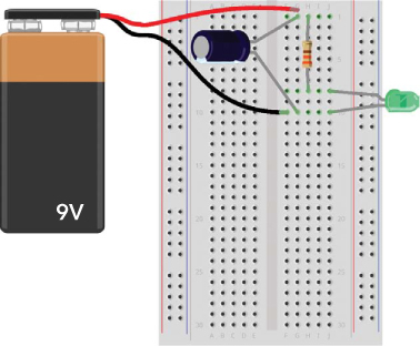
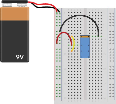
This project demonstrates that a capacitor stores energy. It’s nearly the same circuit you built in “Project #9: Your First Breadboard Circuit” on page 84, but this time, you’re going to add a capacitor. When you remove the battery from the circuit, as shown here, you’ll see that the LED remains lit for a second or two. That’s because the capacitor is powering the LED using its stored energy.
Shopping List

![]() A breadboard (Jameco #20601, Bitsbox #CN329) with at least 30 rows.
A breadboard (Jameco #20601, Bitsbox #CN329) with at least 30 rows.
![]() A standard 9 V battery to power the circuit.
A standard 9 V battery to power the circuit.
![]() A 9 V battery clip (Jameco #11280, Bitsbox #BAT033) to connect the battery to the circuit.
A 9 V battery clip (Jameco #11280, Bitsbox #BAT033) to connect the battery to the circuit.
![]() A standard LED (Jameco #34761, Bitsbox #OP003)
A standard LED (Jameco #34761, Bitsbox #OP003)
![]() A 330 Ω resistor (Jameco #661386, Bitsbox #CR25330R) for limiting the current to the LED.
A 330 Ω resistor (Jameco #661386, Bitsbox #CR25330R) for limiting the current to the LED.
![]() A polarized 1000 µF capacitor (Jameco #158298, Bitsbox #EC1KU25)
A polarized 1000 µF capacitor (Jameco #158298, Bitsbox #EC1KU25)
Step 1: Start with the LED Circuit
Follow the instructions from “Project #9: Your First Breadboard Circuit” on page 84, making sure you end up with a working circuit that lights an LED. Then, disconnect the battery and move on to the next step.
Step 2: Add the Capacitor
Connect your capacitor to the battery. Because the capacitor is polarized, place the pin marked with a minus sign or a zero in the same breadboard row as the battery’s negative leg. Connect the other leg to the same row as the battery’s positive leg, as shown.

Step 3: Charge the Capacitor
Connect the battery to the clip, and the LED should light up. At the same time, the battery should have very quickly charged the capacitor.
Step 4: Use the Capacitor to Light the LED
Watch the LED while removing the battery. The LED shouldn’t turn off right away when you disconnect the battery. Instead, it should stay lit for a second or so and then fade out slowly until there’s no more energy left in the capacitor.
Step 5: What If the Circuit Doesn’t Work?
First, check whether the circuit works without the capacitor. If not, then go back to Step 1 and get the LED circuit working before you move forward.
If the LED lights up with the battery connected but turns off the instant you remove the battery, then something is wrong with the capacitor part of your circuit. Check that the capacitor’s positive leg is connected to the positive battery leg (row 1 in the photo) and that the other leg is connected to the negative battery leg (row 10 in the photo).
If the circuit looks correct, confirm that the capacitor value is at least 1000 µF; the value should be written on the capacitor. If it’s less than 1000 µF, try a bigger capacitor.
DESCRIBING CIRCUITS WITH SYMBOLS
So far, you’ve built circuits with only a few components. To build more interesting electronics projects, you usually need more components. But drawing out every component in a big circuit exactly as it looks in real life can be messy and time-consuming. This is where circuit diagrams, also called schematics, come to the rescue.
In a circuit diagram, each component has its own simple symbol, which lets you draw the whole circuit quickly. As with words and books, until you know what the different symbols mean, a circuit diagram might look a bit complex. Let’s jump right in and learn a few symbols! Here’s a circuit with an LED, a resistor, and a battery, alongside its circuit diagram:
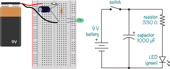
The battery symbol has a + sign to tell you where the positive leg goes. Sometimes you’ll see the battery symbol without the plus sign; in that case, the positive side is the one with the longest line.
NOTE
The battery symbol may be drawn with two lines, with four lines, and sometimes with even more lines. Regardless of the number of lines, just look for the specified voltage and use a battery with the same voltage.
The switch symbol is very simple, and it doesn’t matter which way you draw it. In the LED symbol, the line on the point of the triangle indicates the negative side of the LED, or the cathode. Check that against the “real-life” version, and you can see that the LED’s positive leg is indeed connected to the resistor in both diagrams. The resistor, on the other hand, isn’t polarized, so its symbol doesn’t have any directional markers. There are both polarized and nonpolarized capacitor symbols, but our example shows the polarized version, which has the positive side marked with a + sign. Look at both the circuit and the circuit diagram again—do you agree that they are the same?
Once you learn how to build something just by looking at a circuit diagram, a whole new world will open up for you. You can find circuit diagrams for almost anything on the Internet these days, like radios, MP3 players, walkie-talkies, or whatever you want to build! I’ll teach you more circuit symbols throughout this book as we use more components.
MEET THE RELAY
I was a very curious child, and I always wondered how things worked. To me, electronics devices like the radio or the television were just magical. I had no idea how they worked, and I didn’t believe I’d ever understand how to make one.
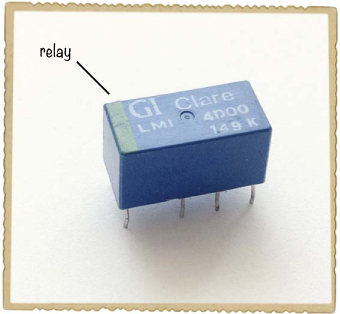
But one day, I asked my dad how it was possible to blink a light automatically. I thought that if I could only understand that, I’d be able to understand more. Fortunately, my dad was an engineer, and he was also good at explaining things in a practical way. When I asked him how to blink a light, he introduced me to a relay, like the one shown here.
Chapter 1 described how you can use switches to turn things on and off. Chapter 2 showed you how to use an electromagnet to move things. Imagine combining the electromagnet with a switch: instead of pushing a button to change the switch’s position, you add an electromagnet that can change the switch position for you. That’s the idea behind the relay, and this illustration shows how it works:
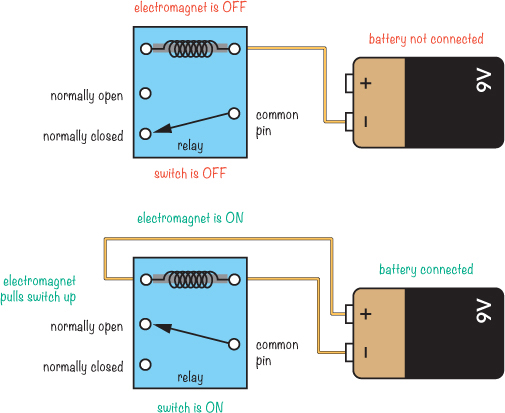
The white dots represent the relay’s pins. Notice that the connections are labeled common pin, normally closed, and normally open. These labels are defined as follows:
Common pin (COM) Connected to either NC or NO
Normally closed (NC) Connected to COM when coil is off
Normally open (NO) Connected to COM when coil is on
When the battery isn’t connected to the relay coil, the electromagnet doesn’t pull, and COM from the switch is connected to NC. But when you connect the battery to the relay coil, the electromagnet turns on, and the switch is pulled so that COM gets connected to NO instead. You can connect or disconnect a battery from the electromagnet to change the position of the switch!
Using the Relay to Blink a Light
If you were to connect a relay to a battery so that the electromagnet connects to the battery through the relay’s COM and NC switch contacts, the electromagnet would turn on and off continuously. Here’s an example relay circuit that’s also connected to a light bulb:
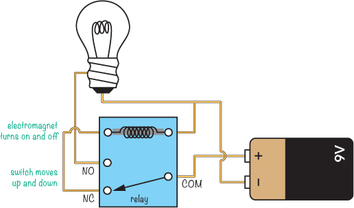
Before you connect the battery in this circuit, the electromagnet would be off, leaving the COM and NC switch contacts connected. With the battery connected to the circuit, the electromagnet would receive power from the battery through the switch. This means it’d pull the switch and connect COM and NO instead, giving the light bulb power from the battery.
But with the switch in this position, the battery would no longer be connected to the coil, and the electromagnet would lose its power. When the electromagnet has no power, the switch falls back to its original position, disconnecting the battery from the light bulb. The battery would power the electromagnet again, and the process I just described would repeat.
In this example, it seems like you’d get a blinking light, right? In theory, yes. But the relay would switch on and off so fast you wouldn’t see the light turn on and off properly! Instead, you’d hear a really fast ticking sound as the relay switched back and forth, but the light would appear to stay dark.
Slowing Down the Blinking
To build a circuit that lets you actually see the light blink, you need to slow down the relay. The capacitor can help with this. In “Project #10: Test a Capacitor” on page 92, adding a capacitor to the LED circuit made the LED stay on for a short time after the battery was disconnected. If you connected a capacitor across the electromagnet in our too-fast blinking-light circuit, the electromagnet would stay on for a bit, too.
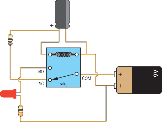
But the electromagnet wouldn’t stay off for long, so in this case, the light would appear to be on all the time. To make it stay off longer, you’d need to slow down the charging of the capacitor so it wouldn’t jump back to fully charged as soon as it discharged. To do this, you could reduce the amount of current flowing into the capacitor. And how do you reduce the amount of current? With a resistor! To blink an LED light with a relay, you’d use a circuit like this one, which we’re going to build next:
PROJECT #11: BLINK A LIGHT!
It’s time for you to build your first blinking light by flashing an LED. Here’s the complete circuit diagram—do you recognize the components?

When connecting a circuit, it’s helpful to connect it in a way that looks like the circuit diagram. That makes it easier to find out what’s wrong if your circuit isn’t working later—and you’ll often find that your circuit doesn’t work on the first try. Tracking down errors and figuring out how to fix them is part of the game!
Shopping List

![]() A breadboard (Jameco #20601, Bitsbox #CN329) with at least 30 rows.
A breadboard (Jameco #20601, Bitsbox #CN329) with at least 30 rows.
![]() Breadboard jumper wires (Jameco #2237044, Bitsbox #CN236) for making easy connections. (Standard hookup wire works, too.)
Breadboard jumper wires (Jameco #2237044, Bitsbox #CN236) for making easy connections. (Standard hookup wire works, too.)
![]() A standard 9 V battery to power the circuit.
A standard 9 V battery to power the circuit.
![]() A 9 V battery clip (Jameco #11280, Bitsbox #BAT033) to connect the battery to the circuit.
A 9 V battery clip (Jameco #11280, Bitsbox #BAT033) to connect the battery to the circuit.
![]() A DPDT or SPDT relay (Jameco #842996, Bitsbox #SW073) with a 5 V, 6 V, or 9 V coil.
A DPDT or SPDT relay (Jameco #842996, Bitsbox #SW073) with a 5 V, 6 V, or 9 V coil.
![]() A standard LED (Jameco #34761, Bitsbox #OP003)
A standard LED (Jameco #34761, Bitsbox #OP003)
![]() A polarized 1000 µF capacitor (Jameco #158298, Bitsbox #EC1KU25)
A polarized 1000 µF capacitor (Jameco #158298, Bitsbox #EC1KU25)
![]() A 100 Ω resistor (Jameco #690620, Bitsbox #CR25100R) for limiting the current to the capacitor.
A 100 Ω resistor (Jameco #690620, Bitsbox #CR25100R) for limiting the current to the capacitor.
![]() A 330 Ω resistor (Jameco #661386, Bitsbox #CR25330R) for limiting the current to the LED.
A 330 Ω resistor (Jameco #661386, Bitsbox #CR25330R) for limiting the current to the LED.
Step 1: Identify the Relay Pins
Not knowing which pin on the relay is which is the biggest source of error when building this circuit, so let’s look at these pins now. To find the function of each pin, look up the datasheet for your relay. A datasheet is a document that tells you how an electrical component works. For a relay, it should say what voltage you need for the electromagnet coil, how much current you can run through the contacts, and so on. You should be able to find a link to the datasheet on the product page where you bought your relay.
For the relay I recommend, the pins are placed as shown here:
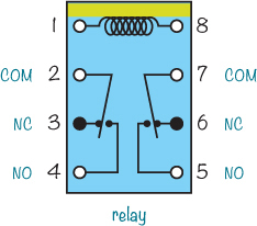
This type of diagram is called a pinout, and it shows the function of each pin. The view is from above with the pins out of sight below the plastic case of the relay. I suggest drawing the pinout on a piece of paper and keeping it on your desk while you connect the circuit so you can check it repeatedly and make sure you’re connecting it the right way.
In this relay, pins 1 and 8 are for the electromagnet coil—you can identify these pins by the line at the top. When you look at the real relay with the line at the top, the pins should be in the same places as in the pinout.
The pinout also shows that there are two switches inside. Pins 2 to 4 make up one switch, and pins 5 to 7 make up the other. Don’t worry about memorizing the relay pins, though. You can always refer to the pinout if you get stuck, and I encourage you to do so whenever you need to. Also, different relay types can have different pinouts.
Step 2: Make the Relay Switch Fast
First, let’s connect the relay so that it switches on and off automatically. Place the relay in the middle of your breadboard, centered over the notch, with one side in each component area. This way, no pin should be connected to any other pins.
Plug your battery clip’s positive leg into the positive supply column on the left, and plug the negative leg into the negative supply column on the same side. Connect a jumper wire from the negative supply column to the same row as the right coil pin (pin 8), shown as row 9 this diagram:
Next, connect a wire from the plus column on the left to the relay’s common switch pin (pin 2). In this diagram, the common pin is in row 12, column B. Then, connect a wire from pin 3 on the relay (the NC pin) to the coil pin (pin 1); this is the yellow wire going from row 14 to row 9 in column B in the diagram. Connect the 9 V battery, and you should hear a really fast ticking. This is the relay turning on and off. Disconnect the battery for now.
Step 3: Make the Relay Stay On Longer
The next step is to slow down the relay by placing a capacitor across the coil of the electromagnet. Connect the capacitor as shown here:

In the diagram, I’ve connected the negative capacitor leg to pin 8 on the relay by plugging it into row 9, column H and connecting the positive leg to pin 1 on the relay at row 9, column D. Whichever holes you use, just make sure you connect the capacitor’s negative leg to the same relay pin as the one you connected the negative supply to. The negative capacitor leg is usually marked with a stripe, a zero, or a minus sign.
Connect the battery to test your circuit. You’ll know it’s working if you hear the telltale ticking sound. The ticking should be much slower now, which means that the relay is staying on for a longer time. But in the instant the relay is turned off, the capacitor should charge again, leaving the relay off for only a fraction of a second. You’ll fix that in the next step, so disconnect the battery again now.
Step 4: Make the Relay Stay Off Longer
Let’s add a resistor before the capacitor to reduce the amount of current that flows and force the capacitor to take more time to charge. To do this, simply replace the wire between pins 1 and 3 on the relay (the yellow wire connected to rows 9 and 14 in my diagrams) with a resistor of about 100 Ω as shown here:

Connect the battery to test it. The relay should stay off a bit longer now, and you’ll recognize this by the “tick-tock” sound of the relay.
Step 5: Add the LED and Resistor
Disconnect the battery and add the LED and the 330 Ω resistor to the circuit. Connect the long leg of the LED to the NO pin of the relay (pin 4). My LED’s long leg is connected to row 16, because the NO pin is plugged into that row. Connect the other leg to an unconnected row below, such as row 19. Connect the resistor from the same row to the negative column on the supply side.
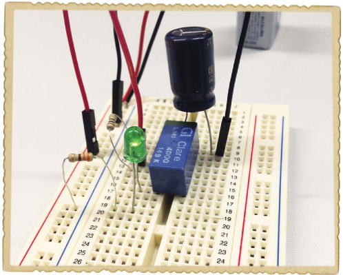
Your breadboard should look something like this:
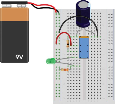
Compare this to the circuit diagram at the beginning of the project to see how the symbols match. Now, connect the battery and watch the light blink!
Step 6: What If the LED Won’t Blink?
If you can’t get the LED to blink, go back to Step 1 and check your work through to Step 4. This should give you a relay that turns on and off automatically. If that works, then you should be able to connect the LED and resistor to have a working circuit.
If the LED still doesn’t blink, confirm you’ve connected it according to the diagrams. Still no luck? Remove the LED and the resistor from the circuit, and then connect only these two to the battery until you can make the LED light up. (Follow the instructions in “Project #9: Your First Breadboard Circuit” on page 84.) If you can’t make the LED light, then your LED may be broken or your resistor may be the wrong value.
Try connecting a relay to the Intruder Alarm you built in Project #2 on page 11 so that when someone tries to enter a room, they can’t turn off the alarm by closing the door. When your relay is triggered by a switch, it should stay on. This diagram shows how you can connect the relay (shown in blue) to the rest of the circuit (shown in black). When the alarm is triggered, the beep will continue to sound until you disconnect the battery.
