
There are two ways to make use of structure definitions in your disassemblies. First, you can reformat memory references to make them more readable by converting numeric structure offsets such as [ebx+8] into symbolic references such as [ebx+ch8_struct.field4]. The latter form provides far more information about what is being referenced. Because IDA uses a hierarchical notation, it is clear exactly what type of structure, and exactly which field within that structure, is being accessed. This technique for applying structure templates is most often used when a structure is being referenced through a pointer. The second way to use structure templates is to provide additional datatypes that can be applied to stack and global variables.
In order to understand how structure definitions can be applied to instruction operands, it is helpful to view each definition as something similar to set of enumerated constants. For example, the definition of ch8_struct in Figure 8-5 might be expressed in pseudo-C as the following:
enum {
   ch8_struct.field1 = 0,
   ch8_struct.field2 = 4,
   ch8_struct.field3 = 6,
   ch8_struct.field4 = 8,
   ch8_struct.field5 = 16
};
Given such a definition, IDA allows you to reformat any constant value used in an operand into an equivalent symbolic representation. Figure 8-7 shows just such an operation in progress. The memory reference [ecx+10h] may represent an access to field5 within a ch8_struct.
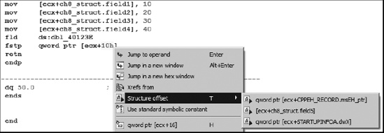
The Structure offset option, available by right-clicking 10h in this case, offers three alternatives for formatting the instruction operand. The alternatives are pulled from the set of structures containing a field whose offset is 16.
As an alternative to formatting individual memory references, stack and global variables can be formatted as entire structures. To format a stack variable as a structure, open the detailed stack frame view by double-clicking the variable to be formatted as a structure and then use Edit ▸ Struct Var (alt-Q) to display a list of known structures similar to that shown in Figure 8-8.

Selecting one of the available structures combines the corresponding number of bytes in the stack into the corresponding structure type and reformats all related memory references as structure references. The following code is an excerpt from the stack-allocated structure example we examined previously:
.text:00401006                 mov     [ebp+var_18], 10
.text:0040100D                 mov     [ebp+var_14], 20
.text:00401013                 mov     [ebp+var_12], 30
.text:00401017                 mov     [ebp+var_10], 40
.text:0040101E                 fld     ds:dbl_40B128
.text:00401024                 fstp    [ebp+var_8]
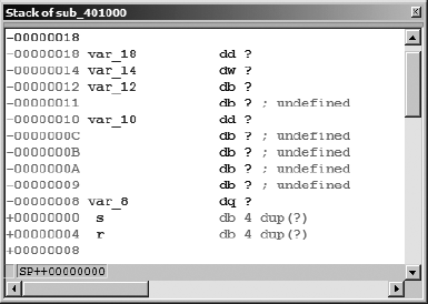
Recall that we concluded that var_18 is actually the first field in a 24-byte structure. The detailed stack frame for this particular interpretation is shown in Figure 8-9.
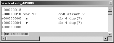
Selecting var_18 and formatting it as a ch8_struct (Edit ▸ Struct Var) collapses the 24 bytes (the size of ch8_struct) beginning at var_18 into a single variable, resulting in the reformatted stack display shown in Figure 8-10. In this case, applying the structure template to var_18 will generate a warning message indicating that some variables will be destroyed in the process of converting var_18 into a structure. Based on our earlier analysis, this is to be expected, so we simply acknowledge the warning to complete the operation.
Following reformatting, IDA understands that any memory reference into the 24-byte block allocated to var_18 must refer to a field within the structure. When IDA encounters such a reference, it makes every effort to resolve the memory reference to one of the defined fields within the structure variable. In this case, the disassembly is automatically reformatted to incorporate the structure layout, as shown here:
.text:00401006                 mov     [ebp+var_18.field1], 10
.text:0040100D                 mov     [ebp+var_18.field2], 20
.text:00401013                 mov     [ebp+var_18.field3], 30
.text:00401017                 mov     [ebp+var_18.field4], 40
.text:0040101E                 fld     ds:dbl_40B128
.text:00401024                 fstp    [ebp+var_18.field5]
The advantage to using structure notation within the disassembly is an overall improvement in the readability of the disassembly. The use of field names in the reformatted display provides a much more accurate reflection of how data was actually manipulated in the original source code.
The procedure for formatting global variables as structures is nearly identical to that used for stack variables. To do so, select the variable or address that marks the beginning of the structure and use Edit ▸ Struct Var (alt-Q) to choose the appropriate structure type. As an alternative for undefined global data only (not stack data), you may use IDA’s context-sensitive menu, and select the structure option to view and select an available structure template to apply at the selected address.