
Chapter 12. Fault tolerance and recovery patterns
In this chapter, you will learn how to incorporate the possibility of failure into the design of your application. We will demonstrate the patterns on the concrete use case of building a resilient computation engine that allows batch job submissions and their execution on elastically provisioned hardware resources. We will build on what you learned in chapters 6 and 7, so you may want to revisit them.
We will start by considering a single component and its failure and recovery strategies and then build up more-complex systems by means of hierarchical composition as well as client–server relationships. In particular, we will discuss the following patterns:
- The Simple Component pattern (a.k.a. the single responsibility principle)
- The Error Kernel pattern
- The Let-It-Crash pattern
- The Circuit Breaker pattern
12.1. The Simple Component pattern
A component shall do only one thing, but do it in full.
This pattern applies wherever a system performs multiple functions or the functions it performs are so complex that they need to be broken into different components. An example is a text editor that includes spell checking: these are two separate functions (editing can be done without spell checking, and spelling can also be checked on the finished text and does not require editing capabilities), but on the other hand, neither of these functions is trivial.
The Simple Component pattern derives from the single responsibility principle that was formulated by Tom DeMarco in his 1979 book Structured Analysis and System Specification (Prentice Hall). In its abstract form, it demands to “maximize cohesion and minimize coupling.” Applied to object-oriented software design, it is usually stated as follows: “A class should have only one reason to change.”[1]
Robert Martin, “Principles of OOD,” May 11, 2005, http://mng.bz/tJIk.
From the discussion of divide et regna in chapter 6, you know that in order to break a large problem into a set of smaller ones, you can find help and orientation by looking at the responsibilities the resulting components will have. Applying the process of responsibility division recursively allows you to reach any desired granularity and results in a component hierarchy that you can then implement.
12.1.1. The problem setting
As an example, consider a service that offers computing capacity in a batch-like fashion: a user submits a job to be processed, stating the job’s resource requirements and including an executable description of the data sources and the computation that is to be performed. The service has to watch over the resources it manages, implement quotas for the resource consumption of its clients, and schedule jobs in a fair fashion. It also has to persistently queue the jobs that it accepts such that clients can rely on their eventual execution.
The task: Your mission is to sketch the components that make up the full batch service, noting for each one its exact responsibility. Start from the top level, and work your way down until you reach components that are concrete and small enough that you could task teams with implementing them.
12.1.2. Applying the pattern
One separation you can immediately conclude is that the service implementation will be made up of two parts: one that does the coordination and that the clients communicate with, and another that is responsible for execution of the jobs; this is shown in figure 12.1. In order to make the entire service elastic, the coordinating part will tap into an external pool of resources and dynamically spin up or down executor instances. You can see that coordination will be a complex task, and therefore you want to break it up further.
Figure 12.1. Initial component separation

Following the flow of a single job request through this system, you start with the job-submission interface that is offered to clients. This part of the system needs to present a network endpoint that clients can contact; it needs to implement a network protocol for this purpose; and it will interact with the rest of the system on behalf of the clients. You could break up responsibility along even finer lines, but for now let us consider this aspect of representing clients within the client as one responsibility; the client interface will thus be the second dedicated component.
Once a job has been accepted and the client has been informed by way of an acknowledgment message, the system must ensure that eventually the job will be executed. This can only be achieved by storing the incoming jobs on some persistent medium, and you might be tempted to place this storage within the client interface component. But you can already anticipate that other parts of the system will have to access these jobs—for example, to start their execution. Thus, in addition to representing the clients, this component would assume responsibility for making job descriptions accessible to the rest of the system, which is in violation of the single responsibility principle.
Another temptation might be to share the responsibility for the handling of job descriptions between the interested parties—at least the client interface and the job executor, as you may surmise—but that would also greatly complicate each of these components, because they would have to coordinate their actions, running counter to the Simple Component pattern’s goal. It is much simpler to keep one responsibility within one component and avoid the communication and coordination overhead that comes with distributing it across multiple components. In addition to these runtime concerns, you also need to consider the implementation: sharing the responsibility means one component needs to know about the inner workings of the other, and their development needs to be tightly coordinated as well. Those are the reasons behind the second part of do only one thing, but do it in full.
This leads you to identify the storage of job descriptions as another segregated responsibility of the system and thereby as the third dedicated component. A valid interjection at this point is that the client interface component may well benefit from persisting incoming jobs within its own responsibility. This would allow shorter response times for job-submission acknowledgment and also make the client interface component independent from the storage component in case of temporary unavailability. But such a persistent queue would only have the purpose of eventually delivering accepted jobs to the storage component, which then would take responsibility for them. Therefore, these notions are not in conflict with each other, and you may implement both if system requirements demand it.
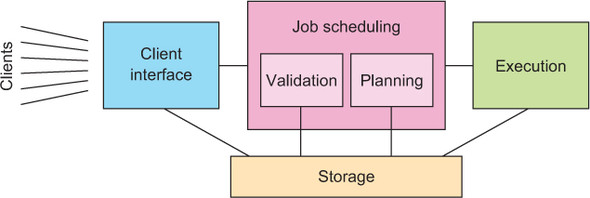
Taking stock, you have now identified client interface, storage, and execution as three dedicated components with non-overlapping responsibilities. What remains to be done is to figure out which jobs to run in what order: this part is called job scheduling. The current state of the system’s decomposition is shown in figure 12.2; now you will apply this pattern recursively until the problem is broken into simple components.
Figure 12.2. Intermediate component separation, with the coordination component broken into three distinct responsibilities

Probably the most complex task in the entire service is to figure out the execution schedule for the accepted jobs, in particular when prioritization or fairness is to be implemented between different clients that share a common pool of resources—the corresponding allocation of computing shares is usually a matter of intense discussion between competing parties.[2] The scheduling algorithm will need to have access to job descriptions in order to extract scheduling requirements (maximum running time, possible expiry deadline, which kind of resources are needed, and so on), so this is another client of the storage component.
The authors have some experience with such allocation between different groups of scientists competing for data analysis resources in order to extract the insights they need for academic publications.
It takes a lot of effort—both for the implementation and at runtime—to plan the execution order of those jobs that are accepted for execution, and this task is independent of deciding which jobs to accept. Therefore, it will be beneficial to separate the responsibility of job validation into its own component. This also has the advantage of removing rejected tasks before they become a burden for the scheduling algorithm. The responsibility for job scheduling now comprises two subcomponents, yet should be represented consistently to the rest of the system as a single component: for example, executors need to be able to retrieve the next job to run at any given time, independent of whether a scheduling run is in progress. For this reason, you place the external interactions in a Job Scheduling component whose validation and planning responsibilities are delegated to subcomponents. The resulting split of responsibilities for the entire system is shown in figure 12.3.
Figure 12.3. The resulting component separation
12.1.3. The pattern, revisited
The goal of the Simple Component pattern is to implement the single responsibility principle. You did that by considering the responsibilities of the overall system at the highest level—client interface, storage, scheduling, and execution—and separating these into dedicated components, keeping an eye on their anticipated communication needs. You then dove into the scheduling component and repeated the process, finding that there are sizable, non-overlapping subresponsibilities that you split out into their own subcomponents. This left the overall scheduling responsibility in a parent component, because you anticipate coordination tasks that will be needed independently of the subcomponents’ functions.
By this process, you arrived at segregated components that can be treated independently during the further development of the system. Each of these has one clearly defined purpose, and each core responsibility of the system lies with exactly one component. Although the overall system and the internals of any component may be complex, the single responsibility principle yields the simplest division of components to further define—it frees you from always having to consider the entire picture when working on smaller pieces. This is its quintessential feature: it addresses the concern of system complexity. Additionally, following the Simple Component pattern simplifies the treatment of failures, a capability you will exploit in the following two patterns.
12.1.4. Applicability
Simple Component is the most basic pattern to follow, and it is universally applicable. Its application may lead you to a finer-grained division of responsibility or to the realization that you are dealing with only a single component—the important part is that afterward you know why you chose your system structure as you did. It helps with all later phases of design and implementation if you document and remember this, because when questions come up later about where to place certain functionality in detail, you can let yourself be guided by the simple question, “What is its purpose?” The answer will directly point you toward one of the responsibilities you identified, or it will send you back to the drawing board if you forgot to consider it.
It is important to remember that this pattern is meant to be applied in a recursive fashion, making sure that none of the identified responsibilities remain too complex or high-level. One word of warning, though: once you start dividing up components hierarchically, it is easy to get carried away and go too far—the goal is simple components that have a real responsibility, not trivial components without a valid reason to exist.
12.2. The Error Kernel pattern
In a supervision hierarchy, keep important application state or functionality near the root while delegating risky operations towards the leaves.
This pattern builds on the Simple Component pattern and is applicable wherever components with different failure probability and reliability requirements are combined into a larger system or application—some functions of the system must never go down, whereas others are necessarily exposed to failure. Applying the Simple Component pattern will frequently leave you in this position, so it pays to familiarize yourself well with the Error Kernel pattern.
This pattern has been established in Erlang programs for decades[3] and was one of the main inspirations for Jonas Bonér to implement an Actor framework—Akka—on the JVM. The name Akka was originally conceived as a palindrome of Actor Kernel, referring to this core design pattern.
The legendary reliability of the Ericsson AXD301 is attributed in part to this design pattern. Its success popularized both the pattern and the Erlang language and runtime that were used in its implementation.
12.2.1. The problem setting
From the discussion of hierarchical failure handling in chapter 7, you know that each component of a Reactive system is supervised by another component that is responsible for its lifecycle management. This implies that if the supervisor component fails, all of its subordinates will be affected by the subsequent restart, resetting everything to a known good state and potentially losing intermediate updates. If the recovery of important pieces of state data is expensive, then such a failure will lead to extensive service downtimes, a condition that Reactive systems aim to minimize.
The task: Consider each of the six components identified in the previous example as a failure domain, and ask yourself which component should be responsible for reacting to its failures as well as which components will be directly affected by them. Summarize your findings by drawing the supervision hierarchy for the resulting system architecture.
12.2.2. Applying the pattern
Because recovering from a component’s failure implies the loss and subsequent re-creation of its state, you will look for opportunities to separate likely points of failure from the places where important and expensive data are kept. The same applies to pieces that provide services that will be highly available: these should not be obstructed by frequent failure or long recovery times. In the example, you can identify the following disparate responsibilities:
- Communication with clients (accepting jobs and delivering their results)
- Persistent storage of job descriptions and their status
- Overall job-scheduling responsibility
- Validation of jobs against quotas or authorization requirements
- Job-schedule planning
- Job execution
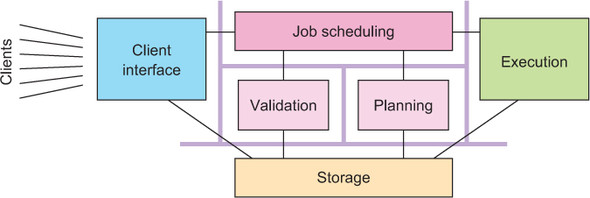
Each of these responsibilities benefits from being decoupled from the rest. For example, communication with clients should not be obstructed by a failure of the job-scheduling logic, just as client-induced failures should not affect the currently running jobs. The same reasoning applies to the other pieces analogously. This is another reason, in addition to the single responsibility principle, for considering them as dedicated components, as shown again in figure 12.4.
Figure 12.4. The six components drawn as separate failure domains
The next step is to consider the failure domains in the system and ask yourself how each of them should recover and how costly that process will be. Toward this end, you can follow the path by which a job travels through the system.
Jobs enter the service through the communication component, which speaks an appropriate protocol with the clients, maintaining protocol state and validating inputs. The state that is kept is short-lived, tied to the communication sessions that are currently open with clients. When this component fails, affected clients will have to reestablish a session and possibly send commands or queries again, but your component does not need to take responsibility for these activities. In this sense, it is effectively stateless—the state that it does keep is ephemeral and local. Recovery of such components is trivially accomplished by terminating the old and starting the new runtime instance.
Once a job has been received from a client, it will need to be persisted, a responsibility that you placed with the storage component. This component will have to allow all other components to query the list of jobs, selecting them by current status or client account and holding all necessary meta-information. Apart from caches for more efficient operation, this component does not hold any runtime state: its function is only to operate a persistent storage medium, and therefore it can easily be restarted in case of failure. This assumes that the responsibility for providing persistence will be split out into a subcomponent—which today is a likely approach—that you would have to consider as well. If the contents of the persistent storage become corrupted, then it is a business decision whether to implement (partial) automatic resolution of these cases or leave it to the operations personnel; automatic recovery would presumably interfere with normal operation of the storage medium and would therefore fall into the storage component’s responsibility.
The next stop of a job’s journey through the batch service is the scheduling component. At the top level, this component is responsible for applying quotas and resource request validation as well as providing the executor component with a queue of jobs to pick up. The latter is crucial for the operation of the overall batch service: without it, the executors would be idle and the system would fail to perform its core function. For this reason, you place this function at the top of the scheduling component’s priorities and correspondingly at the root of its subcomponent hierarchy, as shown in figure 12.5.
Figure 12.5. Job-scheduling subcomponent hierarchy
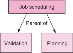
While applying the Simple Component pattern, you identified two subresponsibilities of the scheduling component. The first is to validate jobs against policy rules like per-client quotas[4] or general compatibility with the currently available resource set—it would not do to accept a job that needs 20 executor units when only 15 can be provisioned. Those jobs that pass validation form the input to the second subcomponent that performs job-schedule planning for all currently outstanding and accepted jobs. Both of these responsibilities are task-based: they are started periodically and then either complete successfully or fail. Failure modes include hardware failures as well as not terminating within a reasonable time frame. In order to compartmentalize possible failures, these tasks should not directly modify the persistent state of jobs or the planned schedule but instead report back to their parent component, which then takes action, be that notifying clients (via the client interface component) of jobs that failed their submission criteria or updating the internal queue of jobs to be picked next.
For example, you may want to limit the maximal number of jobs queued by one client—both in order to protect the scheduling algorithm and to enforce administrative limits.
Although restarting the subcomponents proved to be trivial, restarting the parent scheduling component is more complex—it will need to initiate one successful schedule planning run before it can reliably resume performing its duties. Therefore, you keep the important data and the vital functionality at the root and delegate the potentially risky tasks to the leaves. Here again, note that the Error Kernel pattern confirms and reinforces the results of the Simple Component pattern: you will frequently find that the boundaries of responsibilities and failure domains coincide and that their hierarchies match as well.
Once a job has reached the head of the scheduler’s priority queue, it will be picked up for execution as soon as computing resources become available. You have so far considered execution to be an atomic component, but upon considering possible execution failures, you come to the conclusion that you will have to divide its function: the executor needs to keep track of which job is currently running where, and it will also have to monitor the health and progress of all worker nodes. The worker nodes are those components that on receiving a job description will interpret the contained information, contact data sources, and run the analysis code that was specified by the client. Clearly, the failure of each worker will be contained to that node and not spread to other workers or the overall executor, which implies that the execution manager supervises all worker nodes, as shown in figure 12.6.
Figure 12.6. Execution subcomponent hierarchy

If the system is elastic, the executor will also use the external resource-provision mechanism to create new worker nodes or shut down unused ones. The execution manager is also in the position of deciding whether to enlarge or shrink the worker pool, because it naturally monitors the job throughput and can easily be informed about the current job-queue depth—another approach would be to let the scheduler decide the desired pool size. In any case, the executor holds the responsibility of starting, restarting, or stopping worker nodes because it is the only component that knows when it is safe or required to do so.
Analogous to the client interface component, the same reasoning infers that communication with the external resource-provision mechanism should be isolated from the other activities of the execution manager. A communication failure in that regard should not keep jobs from being assigned to already-running executor instances or job-completion notifications from being processed.
The execution of the job is the main purpose of the entire service, but the journey of a job through the components is not yet complete. After the assigned worker node has informed the manager about the completion status, this result needs to be sent back to the storage component in order to be persisted. If the job’s nature was such that it must not be run twice, then the fact that the execution was about to start must also have been persisted in this fashion; in this case, a restart of the execution manager will need to include a check of which jobs were already started but not yet completed prior to the crash, and corresponding failure results will have to be generated. In addition to persisting the final job status, the client will need to be informed about the job’s result, which completes the entire process.
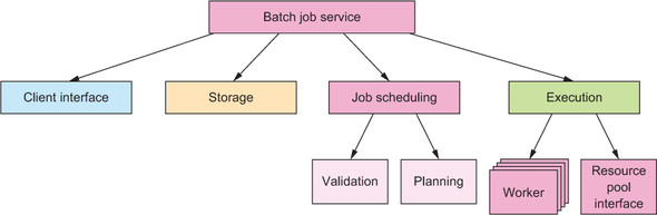
Now that you have illuminated the functions and relationships of the different components, you recognize that you have omitted one in the earlier list of responsibilities: the service itself needs to be orchestrated, composed from its parts, supervised, and coordinated. You need one top-level component that creates the others and arranges for jobs and other messages to be passed between them. In essence, it is this component’s function to oversee the message flow and thereby the business process of the service. This component will be top-level because of its integrating function, which is needed at all times, even though it may be completely stateless by itself. The complete resulting hierarchy is shown in figure 12.7.
Figure 12.7. The hierarchical decomposition of the batch job service
12.2.3. The pattern, revisited
The essence of the previous example can be summarized in the following strategy: after applying the Simple Component pattern, pull important state or functionality toward the top of the component hierarchy, and push activities that carry a higher risk for failure downward towards the leaves. It is expected that responsibility boundaries coincide with failure domains and that narrower subresponsibilities will naturally fall toward the leaves of the hierarchy. This process may lead you to introduce new supervising components that tie together the functionality of components that are otherwise siblings in the hierarchy, or it may guide you toward a more fine-grained component structure in order to simplify failure handling or decouple and isolate critical functions to keep them out of harm’s way. The quintessential function of the Error Kernel pattern is to integrate the operational constraints of the system into its responsibility-based problem decomposition.
12.2.4. Applicability
The Error Kernel pattern is applicable if any of the following are true:
- Your system consists of components that have different reliability requirements.
- You expect components to have significantly different failure probabilities and failure severities.
- The system has important functionality that it must provide as reliably as possible while also having components that are exposed to failure.
- Important information that is kept in one part of the system is expensive to re-create, whereas other parts are expected to fail frequently.
The Error Kernel pattern is not applicable if the following are true:
- No hierarchical supervision scheme is used.
- The system already uses the Simple Component pattern, so it does not have multiple failure probabilities.
- All components are either stateless or tolerant to data loss.
We will discuss the second kind of scenarios in more depth in the next chapter when we present the Active–Active Replication pattern.
12.3. The Let-It-Crash pattern
Prefer a full component restart to internal failure handling.
In chapter 7, we discussed principled failure handling, noting that the internal recovery mechanisms of each component are limited because they are not sufficiently separated from the failing parts—everything within a component can be affected by a failure. This is especially true for hardware failures that take down the component as a whole, but it is also true for corrupted state that is the result of some programming error only observable in rare circumstances. For this reason, it is necessary to delegate failure handling to a supervisor instead of attempting to solve it within the component.
This principle is also called crash-only software:[5] the idea is that transient but rare failures are often costly to diagnose and fix, making it preferable to recover a working system by rebooting parts of it. This hierarchical restart-based failure handling makes it possible to greatly simplify the failure model and at the same time leads to a more robust system that even has a chance to survive failures that were entirely unforeseen.
Both of the following articles are by George Candea and Armando Fox: “Recursive Restartability: Turning the Reboot Sledgehammer into a Scalpel,” USENIX HotOS VIII, 2001, http://dslab.epfl.ch/pubs/recursive_restartability.pdf; and “Crash-Only Software,” USENIX HotOS IX, 2003, https://www.usenix.org/legacy/events/hotos03/tech/full_papers/candea/candea.pdf.
12.3.1. The problem setting
We will demonstrate this design philosophy using the example of the worker nodes that perform the bulk of the work in the batch service whose component hierarchy was developed in the previous two patterns. Each of these is presumably deployed on its own hardware—virtualized or not—that it does not share with other components; ideally, there is no common failure mode between different worker nodes other than a computing center outage.
The problem you are trying to solve is that the workers’ code may contain programming errors that rarely manifest—but when they do, they will impede the ability to process batch jobs. Examples of this kind are very slow resource leaks that can go undetected for a long time but will eventually kill the machine; such a leak could result from open files, retained memory, background threads, and so on, and it may not occur every time but could be caused by a rare coincidence of circumstances. Another example is a security vulnerability that allows the executed batch job to intentionally corrupt the state of the worker node in order to subvert its function and perform unauthorized actions within the service’s private network—such subversion often is not completely invisible and leads to spurious failures that should not be papered over.
The task: Your mission is to consider the components you have identified for the batch service and describe how a crash and restart would affect each of them and which implementation constraints arise from the let-it-crash philosophy.
12.3.2. Applying the pattern
The Let-It-Crash pattern by itself is simple: whenever a component—for example, a worker node—is detected to be faulty, no attempt is made to repair the damage. Instead of doctoring its internal state, you restart it completely, releasing all of its resources and starting it up again from scratch. If you obtained the worker nodes by asking an infrastructure service to provision them, you can go back to the most basic state imaginable: you decommission the old worker node and provision an entirely new one. This way, no corruption or accumulated failure condition can have survived in the fresh instance, because you begin from a known good state again.
Applying this approach to the client interface nodes means all currently active client connections will be severed for the failed node, leading to connection-abort errors in the clients. Upon detecting such an abort condition, the client should try to reconnect, which is your first conclusion. The second follows immediately when considering that the new connection should not be routed to the failed node; this usually means changing the load balancer configuration to remove the failed node. Then, a new node needs to be brought online and added to the load balancer to restore the same processing capacity as before. With these measures, you can confidently crash and restart a client interface node at any given point in time. You do not need to consider the internal communication, because no other components depend on this one: the client interface has only dependencies, no dependents. The consequence of this is that new client requests that a fresh node receives will refer to the storage or scheduling components as the sources of truth—the client interface can be “stateless.”[6]
This word has become so widely (mis)used that it does not stand on its own any longer. The authors’ view is that a truly stateless service that does not contain any mutable internal state does not exist (it would not be a component with a purpose to exist), and a more meaningful interpretation is to equate statelessness with the absence of persistent mutable state.
For the storage component, a node failure means the stored data are invalid or lost—the consequence of either possibility is that the data cannot be relied on any longer, so these states are fundamentally equivalent. Because the purpose of the component is to store data permanently, you will have to distribute storage components as per the discussion in section 2.4. We will cover data replication in the next chapter; for now, it suffices to assume that there will be other storage nodes that hold copies of the data. After stopping the failed node, you will therefore need to start a new one that synchronizes itself with the other replicas, taking on the share of responsibility that the failed node had. If the new node uses the previous node’s permanent storage device, then recovery can be speeded up by synchronizing only those updates that occurred after the failure. It should be noted that failure is not the same as shutting down and starting up again: the storage devices will keep the data across the shutdown, and the system will start up normally afterward—this can even be done in many cases of infrastructure outages (such as network or power failures).
In the case of the scheduling component, a crash and restart means repopulating the internal state from persistent job storage and resuming operations. This is trivial for an aborted planning run or a failure during job validation, and it can also be handled easily for the top-level scheduling component: you used the Error Kernel pattern to keep this piece of software simple so you could assume that a restart cycle takes a sufficiently short time to be deemed an acceptable downtime, unless specific requirements force you to use replication here as well.
The execution component works similarly in that the worker nodes can crash and be restarted as discussed, where the supervisor makes sure the affected batch job is started again on another available node (or on the newly provisioned one). For the resource pool interface, you can tolerate a short downtime while it is restarted, because its services are rarely needed; and when they are needed, reaction times will be of the order of many seconds or even minutes.
12.3.3. The pattern, revisited
We have looked at each of the components in the system’s supervision hierarchy and considered the consequences of a failure and subsequent restart. In some cases, you encounter implementation constraints like having to update the request-routing infrastructure so that the failed node is no longer considered and the replacement is taken into account once it is ready. In other cases, you approach the formulation of SLAs by saying that a short downtime may be acceptable: in a real system, you would quantify this both in the failure frequency (for example, by way of the mean time between failures [MTBF][7]) and the extent of the outage (also called the mean time to repair [MTTR][8]).
This pattern can also be turned around so that components are “crashed” intentionally on a regular basis instead of waiting for failures to occur—this could be termed the Pacemaker pattern. Deliberately inducing failures has been standard operating procedure for a long time in high-availability scenarios, to verify that failover mechanisms are effective and perform according to specification. The concept has been popularized in recent years by the Chaos Monkey employed by Netflix[9] to establish and maintain the resilience of the company’s infrastructure. The chaotic nature of this approach manifests in that single nodes are killed at random without prior selection or human consideration. The idea is that in this way, failure modes are exercised that could potentially be missed in human enumeration of all possible cases. On a higher level, entire data centers and geographic regions are taken offline in a more prepared manner to verify global resource reallocation—this is done on the live production system because no simulation environment could practically emulate the load and client dynamics of such a large-scale application.
At the time of writing, the largest streaming video provider in the United States. Chaos Monkey is part of the Simian Army project that is available as open source software at https://github.com/Netflix/SimianArmy. The approach is described in detail at http://techblog.netflix.com/2012/07/chaos-monkey-released-into-wild.html.
Another way to look at this is to consider the definition of availability: it is the fraction of time during which the system is not in a failure state and thus able to process requests, which in mathematical terms is (MTBF – MTTR) / MTBF. This can be increased either by making MTBF larger—which corresponds to less frequent but possibly extensive failures—or by making MTTR smaller. In the latter case, the maximum consecutive downtime period is smaller and the system operates more smoothly, which is the goal of the Let-It-Crash pattern.
12.3.4. Implementation considerations
Although this pattern is deeply ingrained in Reactive application design already, it is nevertheless documented here to take note of its important consequences on the design of components and their interaction:
- Each component must tolerate a crash and restart at any point in time, just as a power outage can happen without warning. This means all persistent state must be managed such that the service can resume processing requests with all necessary information and ideally without having to worry about state corruption.
- Each component must be strongly encapsulated so that failures are fully contained and cannot spread. The practical realization depends on the failure model for the hierarchy level under consideration; the options range from shared-memory message passing over separate OS processes to separate hardware in possibly different geographic regions.
- All interactions between components must tolerate that peers can crash. This means ubiquitous use of timeouts and circuit breakers (described later in this chapter).
- All resources a component uses must be automatically reclaimable by performing a restart. In an Actor system, this means resources are freed by each Actor on termination or that they are leased from their parent; for an OS process, it means the kernel will release all open file handles, network sockets, and so on when the process exits; for a virtual machine, it means the infrastructure resource manager will release all allocated memory (also persistent filesystems) and CPU resources, to be reused by a different virtual machine image.
- All requests sent to a component must be as self-describing as is practical so that processing can resume with as little recovery cost as possible after a restart.
12.3.5. Corollary: the Heartbeat pattern
The Let-It-Crash pattern describes how failures are dealt with. The other side of this coin is that failures must first be detected before they can be acted on. In particularly catastrophic cases like hardware failures, the supervising component can only detect that something is wrong by observing the absence of expected behavior. This obviously requires that some behavior can be expected, which means supervisor and subordinate must communicate with each other on a regular basis. In cases where there would not otherwise be a reason for such interchange, the supervisor needs to send dummy requests whose sole purpose is to see whether the subordinate is still working properly. Due to their regular and vital nature, these are called heartbeats. The resulting pattern’s diagram is shown in figure 12.8.
Figure 12.8. The supervisor starts the subordinate, and then it performs periodic health checks by exchanging messages with the subordinate until no satisfactory answer is returned.

One caveat of using dedicated heartbeat messages is that the subordinate may have failed in a way that allows heartbeats to be processed, but nothing else will be answered properly. In order to guard against such unforeseen failures, health monitoring should be implemented by monitoring the service quality (failure rate, response latency, and so on) during normal operation where appropriate—sending such statistics to the supervisor on a regular basis can be used as a heartbeat signal at the same time if it is done by the subordinate (as opposed to being done by the infrastructure: for example, by monitoring the state of circuit breakers, as discussed in section 12.4).
12.3.6. Corollary: the Proactive Failure Signal pattern
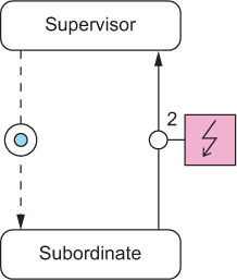
Applying the Heartbeat pattern to all failure modes results in a high level of robustness, but there are classes of failures where patiently waiting for the heartbeat of the suspected component takes longer than necessary: the component can diagnose some failures itself. A prominent example is that all exceptions that are thrown from an Actor implementation are treated as failures—exceptions that are handled inside the Actor usually pertain to error conditions resulting from the use of libraries that use exceptions for this purpose. All uncaught exceptions can be sent by the infrastructure (the Actor library) to the supervisor in a message signaling the failure so that the supervisor can act on them immediately. Wherever this is possible, it should be viewed as an optimization of the supervisor’s response time. The messaging pattern between supervisor and subordinate is depicted in figure 12.9 using the conventions established in appendix A.
Figure 12.9. The supervisor starts the subordinate and reacts to its failure signals as they occur.
Depending on the failure model, it can also be adequate to rely entirely on such measures. This is equivalent to saying that, for example, an Actor is assumed to not have failed until it has sent a failure signal. Monitoring the health of every single Actor in a system is typically forbiddingly expensive, and relying on these failure signals achieves sufficient robustness at the lower levels of the component hierarchy.
It is not uncommon to combine this pattern and the Heartbeat pattern to cover all bases. Where the infrastructure supports lifecycle monitoring—for example, see the DeathWatch[10] feature of Akka Actors—there is an additional way in which the supervisor can learn of the subordinate’s troubles: if the subordinate has stopped itself while the supervisor still expected it to do something (or if the component is not expected to ever stop while the application is running), then the resulting termination notification can be taken as a failure signal as well. The full communication diagram for such a relationship is shown in figure 12.10.
See http://doc.akka.io/docs/akka/2.4.1/general/supervision.html#What_Lifecycle_Monitoring_Means and http://doc.akka.io/docs/akka/2.4.1/scala/actors.html#Lifecycle_Monitoring_aka_DeathWatch.
Figure 12.10. The supervisor first starts the subordinate, and then it performs periodic health checks by exchanging messages with it (step 1) until either no answer is returned or a failure signal is received (step 2).

It is important to note that these patterns are not specific to Akka or the Actor model; we use these implementations only to give concrete examples of their implementation. An application based on RxJava would, for example, use the Hystrix library for health monitoring, allowing components to be restarted as needed. Another example is that the deployment of components as microservices on Amazon EC2 could use the AWS API to learn of some nodes’ termination and react in the same fashion as just described for the DeathWatch feature.
12.4. The Circuit Breaker pattern
Protect services by breaking the connection to their users during prolonged failure conditions.
In previous sections, we discussed how to segregate a system into a hierarchy of components and subcomponents for the purpose of isolating responsibilities and encapsulating failure domains. This pattern describes how to safely connect different parts of the system so that failures do not spread uncontrollably across them. Its origin lies in electrical engineering: in order to protect electrical circuits from each other and introduce decoupled failure domains, a technique was established of breaking the connection when the transmitted power exceeds a given threshold.
Translated to a Reactive application, this means the flow of requests from one component to the next may be broken up deliberately when the recipient is overloaded or otherwise failing. Doing so serves two purposes: first, the recipient gets some breathing room to recover from possible load-induced failures; and second, the sender decides that requests will fail instead of wasting time with waiting for negative replies.
Although circuit breakers have been used in electrical engineering since the 1920s, the use of this principle has been popularized in software design only recently: for example, by Michael Nygard’s book Release It! (Pragmatic Programmers, 2007).
12.4.1. The problem setting
The batch job execution facility designed in the previous three sections will serve you yet again. We already hinted at one situation that would do well to include a circuit breaker: when the service is offered to external clients who submit jobs at their own rate and schedule, and jobs are not naturally bounded by the capacity of the batch system.
To visualize what this means, we will consider a single client that contacts the batch service to submit a single job. The client will get multiple status updates as the submitted job progresses through the system:
- Upon having received and persisted the job description
- Upon having accepted the job for execution, or upon rejecting it due to policy violations
- Upon starting execution
- Upon finishing execution
The first of these steps is very important: it assures the client that there will be further updates about this job because it has been admitted into the system and will at least be examined. Providing this guarantee is costly—it involves storing the job description in nonvolatile and replicated memory—and therefore a client could easily generate more jobs per second than the system can safely ingest. In this case, the client interface would overload the storage subsystem: this would have a ripple effect for the job--scheduling and execution components, which would experience degraded performance when accessing job descriptions for their purposes. The system might still work in this state, but its performance characteristics would be quite different from normal operation; it would be in “overload mode.”
The task: Your mission is to sketch the use of circuit breakers between the client interface component and the storage component to both ensure that clients cannot willfully overload the storage and ensure that the client interface gives timely responses even when the storage component is unreachable or has failed.
12.4.2. Applying the pattern
When implementing the client interface module, you will have to write one piece of code that sends requests to the storage subsystem. If you make sure all such requests take this single route, you will have an easy time reacting to the problematic scenarios outlined earlier. You need to keep track of the response latency for all requests that are made. When you observe that this latency rises consistently above the agreed limit, then you can switch into “emergency mode”: instead of trying new requests, you will answer all subsequent ones immediately with negative replies. You will fabricate the negative replies on behalf of the storage subsystem, because it cannot do even that within the allowed time window under the current conditions.
In addition, you should monitor the failure rate of replies that come back from the storage subsystem. It does not make much sense to keep sending more storage requests when all of them will be answered negatively anyway; instead of wasting network bandwidth, you should again switch into emergency mode, fabricating the negative replies. An example implementation of this scheme in Akka would look like the following listing.
Listing 12.1. Using a circuit breaker to give a failed component time to recover

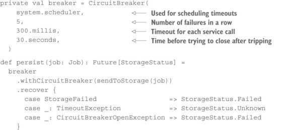
The other piece of client interface code will call the persist method and get back a Future representing the storage subsystem’s reply, but the remote service invocation will be performed only if the circuit breaker is in the closed state. Negative replies (of type StorageStatus.Failed) and timeouts will be counted by the breaker: if it sees five failures in a row, it will transition into the open state in which it immediately provides a response consisting of a CircuitBreakerOpenException. After 30 seconds, exactly one request will be let through to the storage subsystem, and if that comes back successfully and in time, the breaker will flip back into the closed state.
What you have done so far is illustrated in figure 12.11: the client interface will reply to external clients within its allotted time, but in case of a storage-subsystem overload or failure, these replies will be fabricated and negative for all clients. Although this approach protects the system from attacks, it is not the best you can do. Just as in electrical engineering, you need to break circuits at more than one level—what you have built so far is the main circuit breaker for the entire apartment building, but you are lacking the power-distribution boards that limit the damage each individual tenant can do.
Figure 12.11. A circuit breaker between the client interface and the storage subsystem

There is one difference between these per-client circuit breakers and the main one: they do not react primarily to trouble downstream, but rather enforce a maximum current that can flow through them. In computer systems, this is called rate limiting. Instead of tracking the call latencies, you must remember the times of previous requests and reject new requests that violate a stated limit such as “no more than 100 requests in any 2-second interval.” Writing such a facility in Scala is straightforward.
Listing 12.2. Protecting a component by using a rate limiter


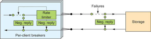
Now you can combine both kinds of circuit breakers to obtain the full picture shown in figure 12.12. Clients are identified by their authentication credentials, so you can assign one CircuitBreaker for each user independent of how many network connections they use. For each client, you maintain a RateLimiter that protects the client interface from being flooded with requests. On the outgoing side, toward the storage component, you use one shared CircuitBreaker to guard against the remote subsystem’s failures. The per-client code could look like the following.
Figure 12.12. Complete circuit breaker setup between the client interface and the storage subsystem
Listing 12.3. Circuit breaker: limiting requests from a client
Advanced usage
It is common practice to gate a client that repeatedly violates its rate limit: gating informs the client that it has made too many requests beyond the allowed rate and will be blocked temporarily. This is an incentive to the writers of client code to properly limit the service calls on their end instead of always sending at full speed—that is an efficient tactic for achieving maximum throughput. In order to do that, you only need to add another circuit breaker, as shown next.
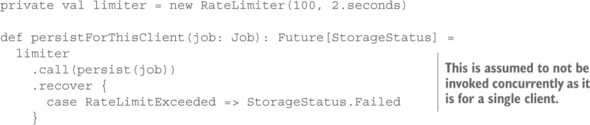
Listing 12.4. Gating a client
private val limiter = new RateLimiter(100, 2.seconds)
private val breaker = CircuitBreaker(system.scheduler,
                                     10, Duration.Zero, 10.seconds)

def persistForThisClient(job: Job): Future[StorageStatus] =
  breaker
    .withCircuitBreaker(limiter.call(persist(job)))
    .recover {
      case RateLimitExceeded              => StorageStatus.Failed
      case _: CircuitBreakerOpenException => StorageStatus.Gated
    }
In order to trip the circuit breaker, the client will have to send 10 requests while being above the rate limit; assuming regular request spacing, this means the client needs to submit at a rate that is at least 10% higher than allowed. In this case, it will be blocked from service for the next 10 seconds, and it will be informed by way of receiving a Gated status reply. Duration.Zero in listing 12.4 has the function of turning off the timeout tracking for individual requests; this is not needed here because it will be performed by the persist call.
12.4.3. The pattern, revisited
You have decoupled the client interface and the storage subsystem by introducing predetermined breaking points on the path from one to the other. Thereby, you have protected the storage from being overloaded in general (the main circuit breaker) and you have protected the client interface’s function from single misbehaving clients (the rate-limiting per-client circuit breakers). Being overloaded is a condition that you should strive to avoid when possible because running at 100% capacity is in most cases less efficient than leaving a little headroom. The reason is that at full capacity, more time is wasted competing for the available resources (CPU time, memory bandwidth, caches, IO channels) than it is when requests can travel through the system mostly unhindered by congestion.
The second problem we have considered here is that the client interface cannot acknowledge reception of a job description before it receives the successful reply from the storage subsystem. If this reply does not arrive within the allotted time, then the response to the client will be delayed for longer than the SLA allows—the service will violate its latency bound. This means during time periods when the storage subsystem fails to answer promptly, the client interface will have to come to its own conclusions; if it cannot ask another (nonlocal) component, then it must locally determine the appropriate response to its own clients. You have also used the circuit breaker to protect the client interface from failures of the storage subsystem, fabricating negative responses in case no others are readily available.
In addition, you have seen that the circuit breaker you installed for overload protection handles the situation where the storage subsystem does not answer successfully or in time—the reaction is independent of the underlying reason. This makes the system more resilient compared to handling every single error case separately. And this is what is meant by bulkheading failure domains to achieve compartmentalization and encapsulation.
12.4.4. Applicability
This pattern is applicable wherever two decoupled components communicate and where failures—foreseen or unexpected—will not travel upstream to infect and slow other components, or where overload conditions will not travel downstream to induce failure. Decoupling has a cost in that all calls pass through another tracking step, and timeouts need to be scheduled. Hence, it should not be applied at too fine a level of granularity; it is most useful between different components in a system. This applies especially to services that are reached via network connections (such as authentication providers and persistent storage), where the circuit breaker also reacts appropriately to network failures by concluding that the remote service is not currently reachable.
Another important aspect of using circuit breakers is that monitoring their state reveals interesting insight into the runtime behavior and performance of a service. When circuit breakers trip while protecting a given service, operations personnel will usually want to be alerted in order to look into the outage.
Note
A circuit breaker is a means to fail fast—it must not be used to postpone requests and send them later. The problem with such a scheme is that when the circuit breaker closes, the deferred requests will likely overload the target system. This phenomenon is called a thundering herd, and it can create feedback loops that lead to a system oscillating between being unavailable and being overloaded.
12.5. Summary
In this chapter, we have covered a lot of ground on the design and implementation of resilient systems:
- We described simple components that obey the single responsibility principle.
- You saw the application of hierarchical failure handling in practice while implementing the Error Kernel pattern.
- We noted the implications of relying on component restarts to recover from failure, in our discussion of the Let-It-Crash pattern.
- You learned how to decouple components from each other using the Circuit Breaker pattern for either side’s protection.
In the next chapter, we will dive into stateful replication patterns in order to implement components that are impervious to outages at varying degrees of downtime and implementation complexity. Although these patterns are also related to fault tolerance and recovery, they warrant a chapter of their own.