Chapter 3. The Arduino Platform
Arduino is composed of two major parts: an Arduino board, which is the piece of hardware you work on when you build your objects; and the Arduino Integrated Development Environment, or IDE, the piece of software you run on your computer. You use the IDE to create a sketch (a little computer program) that you upload to the Arduino board. The sketch tells the board what to do.
Not too long ago, working on hardware meant building circuits from scratch, using hundreds of different components with strange names like resistor, capacitor, inductor, transistor, and so on. Every circuit was wired to do one specific application, and making changes to the circuit required you to cut wires, solder connections, and more.
With the appearance of digital technologies and microprocessors, these functions, which were once implemented with wires, were replaced by software. Software is easier to modify than hardware. With a few keypresses, you can radically change the logic of a device and try two or three versions in the same amount of time that it would take you to solder a couple of resistors.
The Arduino Hardware
The Arduino board is a small microcontroller board, which is a small circuit (the board) that contains a whole computer on a small chip (the microcontroller).
This computer is at least a thousand times less powerful than the MacBook I’m using to write this, but it’s a lot cheaper and very useful for building interesting devices.
—Massimo
Look at the center of the Arduino Uno board: you’ll see a rectangular black piece of plastic with 28 “legs” (or possibly a tiny square piece of plastic if you have the SMD edition)—that chip is the ATmega328, the heart of your board.
Note
In fact, there are a variety of Arduino boards, but the most common one by far is the Arduino Uno, which is described here. In Chapter 9 we give a brief overview of the entire Arduino family, including what sets the new ARM family apart from the AVR boards.
We (the Arduino team) have placed on this board all the components that are required for this microcontroller to work properly and to communicate with your computer. The version of the board we’ll use mostly in this book is the Arduino Uno, which is the simplest one to use and the best one for learning on. Almost everything we’ll talk about applies to all Arduinos, including the most recent ones as well as the earlier ones.
In Figure 3-1, you see that the Arduino has a row of strips at the top and the bottom with lots of labels. These strips are the connectors, which are used to attach to sensors and actuators. (A sensor senses something in the physical world and converts it to a signal a computer can understand, while an actuator converts a signal from a computer into an act in the physical world. You’ll learn much more about sensors and actuators later in this book.)
At first, all those connectors might be a little confusing. Here is an explanation of the input and output pins you’ll learn to use in this book. Don’t worry if you’re still confused after reading this—there are many new concepts in this book that might take you a while to get used to. We’ll repeat these explanations a number of different ways, and they’ll especially start making sense to you once you start building circuits and experiencing the results.
- 14 Digital I/O (input/output) pins, numbered 0–13.
-
These pins can be either inputs or outputs. Inputs are used to read information from sensors, while outputs are used to control actuators. You will specify the direction (in or out) in the sketch you create in the IDE. Digital inputs can only read one of two values, and digital outputs can only output one of two values (HIGH and LOW).
- 6 Analogue In pins (pins 0–5)
-
The analogue input pins are used for reading voltage measurements from analogue sensors. In contrast to digital inputs, which can distinguish between only two different levels (HIGH and LOW), analogue inputs can measure 1,024 different levels of voltage.
- 6 Analogue Out pins (pins 3, 5, 6, 9, 10, and 11)
-
These are actually six of the digital pins that can perform a third function: they can provide analogue output. As with the digital I/O pins, you specify what the pin should do in your sketch.
The board can be powered from your computer’s USB port, most USB chargers, or an AC adapter (9 volts recommended, 2.1 mm barrel tip, center positive). Whenever power is provided at the power socket, Arduino will use that, and if there is no power at the power socket, Arduino will use power from the USB socket. It’s safe to have power at both the power socket and the USB socket.
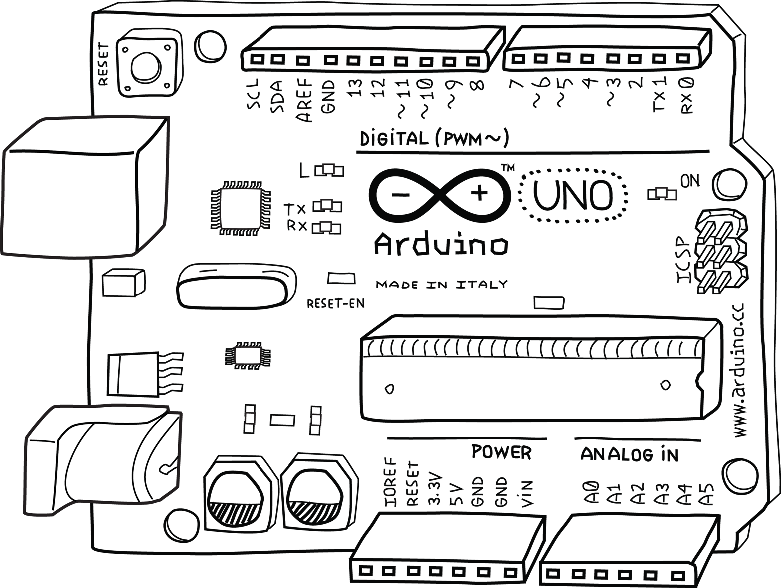
Figure 3-1. The Arduino Uno
The Software Integrated Development Environment (IDE)
The IDE is a special program running on your computer that allows you to write sketches for the Arduino board in a simple language modeled after the Processing language. The magic happens when you press the button that uploads the sketch to the board: the code that you have written is translated into the C language (which is generally quite hard for a beginner to use), and is passed to the avr-gcc compiler, an important piece of open-source software that makes the final translation into the language understood by the microcontroller. This last step is quite important, because it’s where Arduino makes your life simple by hiding away most of the complexities of programming microcontrollers.
The programming cycle on Arduino is basically as follows:
-
Plug your board into a USB port on your computer.
-
Write a sketch that will bring the board to life.
-
Upload this sketch to the board through the USB connection and wait a couple of seconds for the board to restart.
-
Watch as the board executes (performs) the sketch that you wrote.
Installing Arduino on Your Computer
To program the Arduino board, you must first install the IDE by downloading the appropriate file from the Arduino website. Choose the right version for your operating system. (For Windows choose the option Win 7 and Newer). On the next page of the website you may chose to make a financial contribution to support the Arduino IDE, but you may also click the button that says JUST DOWNLOAD. Save the file and then proceed with the appropriate instructions in the following sections.
Installing the IDE: MacOS
When the file download has finished, depending on your browser settings, it may be automatically expanded or you may need to manually expand it, usually by double-clicking on it.
Drag the Arduino application into your Applications folder.
Configuring the Drivers: MacOS
The Arduino Uno uses a driver provided by the MacOS operating system, so there is nothing to install.
Now that the IDE is installed, connect your Arduino Uno to your Mac via a USB cable.
The green LED labeled PWR on the board should come on, and the yellow LED labeled L should start blinking.
Note
You might see a pop-up window telling you that a new network interface has been detected.
If that happens, Click Network Preferences, and when it opens, click Apply. The Uno will show up as Not Configured, but it’s working properly. Quit System Preferences.
Now that you’ve configured the software, you need to select the proper port to communicate with the Arduino Uno.
Port Identification: MacOS
Invoke the Arduino IDE, either through the Applications folder or by using Spotlight.
From the Tools menu in the Arduino IDE, select Serial Port and then select the port that begins with /dev/cu.usbmodem or /dev/tty.usbmodem. They will probably also say Arduino/Genuino Uno following the port name. Both of these ports refer to your Arduino board, and it makes no difference which one you select.
Figure 3-2 shows the list of ports.
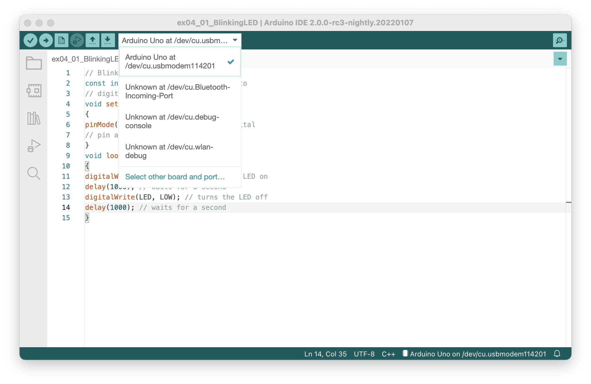
Figure 3-2. The Arduino IDE’s list of serial ports on a Mac
You’re almost done! The final thing you should check is that Arduino is configured for the type of board you’re using.
From the Tools menu in the Arduino IDE, select Board, and then select Arduino Uno. If you have a different board, you’ll need to select that board type (the name of the board is printed next to the Arduino symbol).
Congratulations! Your Arduino software is installed, configured, and ready to use. You’re ready to go on to Chapter 4.
Note
If you have trouble with any of these steps, see Chapter 11, Troubleshooting.
Installing the IDE: Windows
When the file download has finished, double-click to open the installer.
You will be shown a license. Read the license, and if you agree with it, click the I Agree button.
You will be given a list of components to install, and, by default, all of them will be selected. Leave them all selected and click Next.
You will be asked to select an installation folder, and the installer will propose a default for that. Unless you have a good reason not to, accept the default and click Install.
The installer will display its progress as it extracts and installs the files.
After the files are installed, a window will pop up asking for permission to install the drivers. Click Install.
When the installer has completed, click Close to finish.
Configuring the Drivers: Windows
Now that the IDE is installed, connect your Arduino Uno to your computer via a USB cable.
The green LED labeled PWR on the board should come on, and the yellow LED labeled L should start blinking.
The Found New Hardware Wizard window comes up, and Windows should automatically find the right drivers.
Note
If you have trouble with any of these steps, see “Problems Installing Drivers on Windows” in Chapter 11.
Now that the driver has been configured, you need to select the proper port to communicate with the Arduino Uno.
Port Identification: Windows
Run the Arduino IDE, either using a desktop shortcut or the Start menu.
From the Tools menu in the Arduino IDE, select Serial Port. You will see one or more COM ports with different numbers. One of the ports will probably say Arduino/Genuino Uno following the port name. This is the one to select.
If none of the ports say Arduino/Genuino Uno following the port name, there is an alternative way to identify the correct port:
- Make a note of which numbers are available.
- Unplug your Arduino from your computer, look at the list of ports again, and see which COM port vanishes. Plug your Arduino back in and select the port that appears.
(It might take a moment or two for the port to vanish, and you may have to leave the Tools menu and open it again to refresh the list of ports.)
Note
If you have trouble identifying the COM port used by your Arduino Uno, see “Identifying the Arduino COM Port on Windows” in Chapter 11.
Once you’ve figured out the COM port assignment, you can select that port from the Tools→Serial Port menu in the Arduino IDE.
You’re almost done! The final thing you should check is that Arduino is configured for your type of board.
From the Tools menu in the Arduino IDE, select Board and select Arduino Uno. If you have a different board, you’ll need to select that board type (the name of the board is printed next to the Arduino symbol).
Installing the IDE: Linux
When the file download has finished, go to the folder to which the file was downloaded, which is typically
~/Downloads
tar xf arduino-ide_2.0.0-rc3_Linux_64bit.tar.xz
(or whatever filename you downloaded.) This will take a few seconds during which nothing is displayed. When it finishes you will find a new folder:
arduino-ide_2.0.0-rc3_Linux_64bit
mv arduino-ide_2.0.0-rc3_Linux_64bit ~
Granting Permission on the Serial Ports: Linux
The serial ports that the Arduino uses are normally restricted to administrators, so you will need to grant yourself permission to use those serial ports. Do this by adding yourself to the dialout group by typing:
sudo usermod -a -G dialout $USER
you will be asked to provide your password to authenticate. After typing your password the command is finished, but it won’t take effect until the next time you restart the session, so either log out and back in again, or reboot.
Now that you’ve installed the software, you need to select the proper port to communicate with the Arduino Uno.
Port Identification: Linux
Invoke the Arduino IDE by typing:
~/arduino-ide_2.0.0-rc3_Linux_64bit/arduino
From the Tools menu in the Arduino IDE, select Serial Port. You will see one or more serial ports with names like /dev/tty. One of the ports will say Arduino/Genuino Uno following the port name. This is the one to select.
Once you’ve figured out the serial port assignment, you can select that port from the Tools→Serial Port menu in the Arduino IDE.
You’re almost done! The final thing you should check is that Arduino is configured for your type of board.
From the Tools menu in the Arduino IDE, select Board and select Arduino Uno. If you have a different board, you’ll need to select that board type (the name of the board is printed next to the Arduino symbol).
Congratulations! Your Arduino software is installed, configured, and ready to use. You’re ready to go on to Chapter 4.