
Chapter 6. Processing with an Arduino Lamp
In this chapter, we’re going to see how to put together a working application using what you have learned in the previous chapters. This chapter should show you how every single example can be used as a building block for a complex project.
Here is where the wannabe designer in me comes out. We’re going to make the twenty-first-century version of a classic lamp by my favourite Italian designer, Joe Colombo. The object we’re going to build is inspired by a lamp called Aton from 1964.
—Massimo
The lamp, as you can see in Figure 6-1, is a simple sphere sitting on a base with a large hole to keep the sphere from rolling off your desk. This design allows you to orient the lamp in different directions.
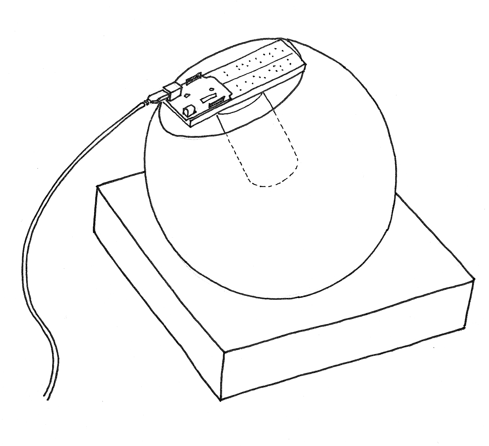
Figure 6-1. The finished lamp
In terms of functionality, we want to build a device that would connect to the Internet, fetch the current list of articles on the Make blog, and count how many times the words “peace,” “love,” and “Arduino” are mentioned. With these values, we’re going to generate a colour and display it on the lamp. The lamp itself has a button we can use to turn it on and off, and a light sensor for automatic activation.
Planning
Let’s look at what we want to achieve and what bits and pieces we need. First of all, we need Arduino to be able to connect to the Internet. As the Arduino board has only a USB port, we can’t plug it directly into an Internet connection, so we need to figure out how to bridge the two. Usually what people do is run an application on a computer that will connect to the Internet, process the data, and send Arduino some simple bit of distilled information.
Arduino is a simple computer with a small memory; it can’t process large files easily, and when we connect to an RSS feed, we’ll get a very verbose XML file that would require a lot more RAM. On the other hand, your laptop or desktop computer has much more RAM and is much better suited for this kind of work, so we’ll implement a proxy to simplify the XML using the Processing language to run on your computer.
Get Processing from https://processing.org/download.
The proxy does the following work for us: it downloads the RSS feed from http://makezine.com and extracts all the words from the resulting XML file. Then, going through all of them, it counts the number of times “peace,” “love,” and “Arduino” appear in the text. With these three numbers, we’ll calculate a colour value and send it to Arduino. The Arduino code, in turn, will send to the computer the amount of light measured by the sensor, which the Processing code will then display on the computer screen.
On the hardware side, we’ll combine the pushbutton example, the light sensor example, the PWM LED control (multiplied by 3!), and serial communication. See if you can identify each of these circuits when you build it in “Assembling the Circuit”. This is how typical projects are made.
As Arduino is a simple device, we’ll need to codify the colour in a simple way. We’ll use the standard way that colours are represented in HTML: # followed by six hexadecimal digits.
Hexadecimal numbers are handy, because each 8-bit number is stored in exactly two characters; with decimal numbers this varies from one to three characters. Predictability also makes the code simpler: we wait until we see a #, and then we read the six characters that follow into a buffer (a variable used as a temporary holding area for data). Finally, we turn each group of two characters into a byte that represents the brightness of one of the three LEDs.
Coding
There are two sketches that you’ll be running: the Processing sketch and the Arduino sketch. Example 6-1 is the code for the Processing sketch. You can also download it from the example code link on the book’s catalog page.
Example 6-1. Arduino Networked Lamp
Parts of the code are inspired by a blog post by Tod E. Kurt (http://todbot.com).
importprocessing.serial.*;importjava.net.*;importjava.io.*;importjava.util.*;Stringfeed="http://makezine.com/feed/";intinterval=5*60*1000;// retrieve feed every five minutes;intlastTime;// the last time we fetched the contentintlove=0;intpeace=0;intarduino=0;intlight=0;// light level measured by the lampSerialport;colorc;Stringcs;Stringbuffer="";// Accumulates characters coming from ArduinoPFontfont;voidsetup(){size(640,480);frameRate(10);// we don't need fast updatesfont=createFont("Helvetica",24);fill(255);textFont(font,32);// IMPORTANT NOTE:// The first serial port retrieved by Serial.list()// should be your Arduino. If not, uncomment the next// line by deleting the // before it, and re-run the// sketch to see a list of serial ports. Then, change// the 0 in between [ and ] to the number of the port// that your Arduino is connected to.//println(Serial.list());StringarduinoPort=Serial.list()[0];port=newSerial(this,arduinoPort,9600);// connect to ArduinolastTime=millis();fetchData();}voiddraw(){background(c);intn=(lastTime+interval-millis())/1000;// Build a colour based on the 3 valuesc=color(peace,love,arduino);cs="#"+hex(c,6);// Prepare a string to be sent to Arduinotext("Arduino Networked Lamp",10,40);text("Reading feed:",10,100);text(feed,10,140);text("Next update in "+n+" seconds",10,450);text("peace",10,200);text(" "+peace,130,200);rect(200,172,peace,28);text("love ",10,240);text(" "+love,130,240);rect(200,212,love,28);text("arduino ",10,280);text(" "+arduino,130,280);rect(200,252,arduino,28);// write the colour string to the screentext("sending",10,340);text(cs,200,340);text("light level",10,380);rect(200,352,light/10.23,28);// this turns 1023 into 100if(n<=0){fetchData();lastTime=millis();}port.write(cs);// send data to Arduinoif(port.available()>0){// check if there is data waitingintinByte=port.read();// read one byteif(inByte!=10){// if byte is not newlinebuffer=buffer+char(inByte);// just add it to the buffer}else{// newline reached, let's process the dataif(buffer.length()>1){// make sure there is enough data// chop off the last character, it's a carriage return// (a carriage return is the character at the end of a// line of text)buffer=buffer.substring(0,buffer.length()-1);// turn the buffer from string into an integer numberlight=int(buffer);// clean the buffer for the next read cyclebuffer="";// We're likely falling behind in taking readings// from Arduino. So let's clear the backlog of// incoming sensor readings so the next reading is// up-to-date.port.clear();}}}}voidfetchData(){// we use these strings to parse the feedStringdata;Stringchunk;// zero the counterslove=0;peace=0;arduino=0;try{URLurl=newURL(feed);// An object to represent the URL// prepare a connectionURLConnectionconn=url.openConnection();conn.connect();// now connect to the Website// this is a bit of virtual plumbing as we connect// the data coming from the connection to a buffered// reader that reads the data one line at a time.BufferedReaderin=newBufferedReader(newInputStreamReader(conn.getInputStream()));// read each line from the feedwhile((data=in.readLine())!=null){StringTokenizerst=newStringTokenizer(data,""<>,.()[] ");// break it downwhile(st.hasMoreTokens()){// each chunk of data is made lowercasechunk=st.nextToken().toLowerCase();if(chunk.indexOf("love")>=0)// found "love"?love++;// increment love by 1if(chunk.indexOf("peace")>=0)// found "peace"?peace++;// increment peace by 1if(chunk.indexOf("arduino")>=0)// found "arduino"?arduino++;// increment arduino by 1}}// Set 64 to be the maximum number of references we care about.if(peace>64)peace=64;if(love>64)love=64;if(arduino>64)arduino=64;peace=peace*4;// multiply by 4 so that the max is 255,love=love*4;// which comes in handy when building aarduino=arduino*4;// colour that is made of 4 bytes (ARGB)}catch(Exceptionex){// If there was an error, stop the sketchex.printStackTrace();System.out.println("ERROR: "+ex.getMessage());}}
There is one thing you need to do before the Processing sketch will run correctly: you need to confirm that the sketch is using the correct serial port for talking to Arduino. You’ll need to wait until you’ve assembled the Arduino circuit and uploaded the Arduino sketch before you can confirm this. On some systems, this Processing sketch will run fine. However, if you don’t see anything happening on the Arduino and you don’t see any information from the light sensor appearing onscreen, find the comment labeled IMPORTANT NOTE in the Processing sketch and follow the instructions there.
Note
If you’re on a Mac, there’s a good chance your Arduino will be on the last serial port in the list. If so, you can replace the0 in Serial.list()[0] with Serial.list().length -1. This subtracts one from the length of the list of all serial ports; array indexes count from zero, but length tells you the size of the list (counting from one), so you need to subtract one to get the actual index.Example 6-2 is the Arduino sketch. You can also download it from the example code link on the book’s catalog page.
Example 6-2. Arduino Networked Lamp (Arduino sketch)
constintSENSOR=0;constintR_LED=9;constintG_LED=10;constintB_LED=11;constintBUTTON=12;intval=0;// variable to store the value coming from the sensorintbtn=LOW;intold_btn=LOW;intstate=0;charbuffer[7];intpointer=0;byteinByte=0;byter=0;byteg=0;byteb=0;voidsetup(){Serial.begin(9600);// open the serial portpinMode(BUTTON,INPUT);}voidloop(){val=analogRead(SENSOR);// read the value from the sensorSerial.println(val);// print the value to// the serial portif(Serial.available()>0){// read the incoming byte:inByte=Serial.read();// If the marker's found, next 6 characters are the colourif(inByte=='#'){while(pointer<6){// accumulate 6 charsbuffer[pointer]=Serial.read();// store in the bufferpointer++;// move the pointer forward by 1}// now we have the 3 numbers stored as hex numbers// we need to decode them into 3 bytes r, g and br=hex2dec(buffer[1])+hex2dec(buffer[0])*16;g=hex2dec(buffer[3])+hex2dec(buffer[2])*16;b=hex2dec(buffer[5])+hex2dec(buffer[4])*16;pointer=0;// reset the pointer so we can reuse the buffer}}btn=digitalRead(BUTTON);// read input value and store it// Check if there was a transitionif((btn==HIGH)&&(old_btn==LOW)){state=1-state;}old_btn=btn;// val is now old, let's store itif(state==1){// if the lamp is onanalogWrite(R_LED,r);// turn the leds onanalogWrite(G_LED,g);// at the colouranalogWrite(B_LED,b);// sent by the computer}else{analogWrite(R_LED,0);// otherwise turn offanalogWrite(G_LED,0);analogWrite(B_LED,0);}delay(100);// wait 100ms between each send}inthex2dec(bytec){// converts one HEX character into a numberif(c>='0'&&c<='9'){returnc-'0';}elseif(c>='A'&&c<='F'){returnc-'A'+10;}}
Assembling the Circuit
Figure 6-2 shows how to assemble the circuit. Just as you did in “Controlling Light with PWM” in Chapter 5, use a 220-ohm resistor (red-red-brown) with each LED, and just as you did in “Analogue Input”, use a 10 K ohm resistor with the photoresistor.
Remember from “Controlling Light with PWM” that LEDs are polarized: in this circuit, the anode (long lead, positive) should go to the right, and the cathode (short lead, negative) to the left. Figure 6-2 also shows the flattened side of the LED, which indicates the cathode.
Build the circuit as shown, using one red, one green, and one blue LED. Next, load the sketches into Arduino and Processing. Upload the Arduino sketch to the Arduino, and then run the Processing sketch and try it out (you will need to press the button to get the lamp to come on). If you run into any problems, check Chapter 11.
Instead of using three separate LEDs, you can use a single RGB LED, which has four leads coming off it. You’ll hook it up in much the same way as the LEDs shown in Figure 6-2, with one change: instead of three separate connections to the ground pin on Arduino, you’ll have a single lead (called the common cathode) going to ground.

Figure 6-2. The Arduino Networked Lamp circuit
Adafruit sells a four-lead RGB LED for a few dollars. Also, unlike discrete single-colour LEDs, the longest lead on this kind of RGB LED is the one that goes to ground. The three shorter leads will need to connect to Arduino pins 9, 10, and 11 (with a 220-ohm resistor between the leads and the pins, just as with the separate red, green, and blue LEDs).
The Maker Shed Getting Started with Arduino Kit includes an RGB LED as well.
Note
The Arduino sketch is designed to work with a common cathode RGB LED (one where the long lead goes to ground). If you’re getting the wrong output, you might have a common anode RGB LED. If that’s the case, change the code where you set the LED intensity as shown (you are basically inverting the values; where you used 0, you’d now use 255):
  if (state == 1) { // if the lamp is on
    analogWrite(R_LED, 255 - r);  // turn the leds on
    analogWrite(G_LED, 255 - g);  // at the colour
    analogWrite(B_LED, 255 - b);  // sent by the computer
  } else {
    analogWrite(R_LED, 255);  // otherwise turn off
    analogWrite(G_LED, 255);
    analogWrite(B_LED, 255);
  }
Now let’s complete the construction by placing the breadboard into a glass sphere. The simplest and cheapest way to do this is to buy an IKEA FADO table lamp. It’s now selling for about US$19.99/€14.99/£11.99 (ahh, the luxury of being European).
Here’s How to Assemble It
Unpack the lamp and remove the cable that goes into the lamp from the bottom. You will no longer be plugging this into the wall.
You can use a rubber band to strap the Arduino to the breadboard, and then hot-glue the breadboard onto the back of the lamp, as shown in Figure 6-1. Leave some room so that you can insert the LED and glue it in place.
Solder longer wires to the RGB LED and glue it where the lightbulb used to be. Connect the wires coming from the LED to the breadboard (where it was connected before you removed it). You can save a bit of time by noting that you will need only one connection to ground, whether you’re using the RGB LED or three separate LEDs.
Now find a nice piece of wood with a hole that can be used as a stand for the sphere, or just cut the top of the cardboard box that came with the lamp at approximately 5 cm (or 2″) and make a hole with a diameter that cradles the lamp. Reinforce the inside of the cardboard box by using hot glue all along the inside edges, which will make the base more stable.
Place the sphere on the stand and bring the USB cable out of the top and connect it to the computer.
Fire off your Processing code, press the On/Off button, and watch the lamp come to life. Invite your friends over and amaze them!
As an exercise, try to add code that will turn on the lamp when the room gets dark. Other possible enhancements are as follows:
-
Add tilt sensors to turn the lamp on or off by rotating it in different directions.
-
Add a PIR sensor to detect when somebody is around, and turn it off when nobody is there to watch.
-
Create different modes so that you can get manual control of the colour or make it fade through many colours.